All Posts (14048)

Sort by

Autonomous monocopter arrives

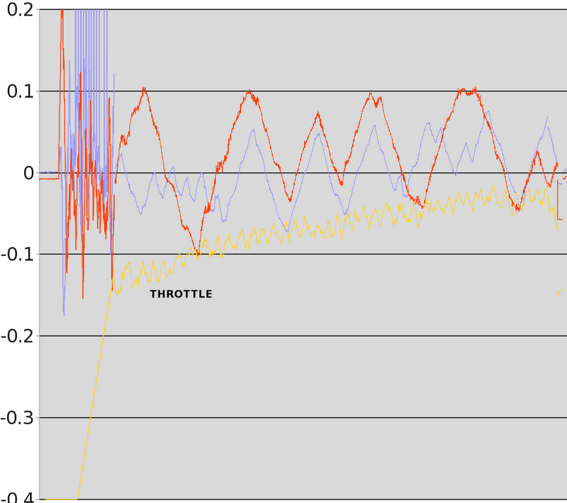
That there is the culmination of 30 months of off & on, hard work. The 1st stable hover of the Marcy 1 monocopter, under computer control. The last items were getting the takeoff as stable as possible, getting the altitude as stable as possible, aligning the azimuth as close to the camera angle as possible, & trying many PID values.  Not only does it take off autonomously, but it can't be flown manually at all in this space.

There was a time when just a takeoff that stable was considered impossible, but we made it happen. Then there was a time when controlling the altitude of such a slowly spinning rotor was considered impossible, but we got it controlled. Finally, horizontal position was not considered controllable, but we managed to control it.

It's still a very unstable aircraft & this is the smallest space it could possibly fly in. The instability seems to be mainly from air turbulence building up from its own downwash, but there's just enough control with exactly the right calibration values to keep it in the air.

A descent was commanded near the end & the motor was killed, because 2 minutes is the point where it overheats. The video is from the machine vision camera.


Then of course, there's the Feigao.

feigao03.jpg


Always looking for punishment, we got another Feigao.   This was 5250kV, 12 x 22mm.  It may have been the same motor in the same store 3 years ago, but which we avoided because either the kV wasn't the highest or it was more expensive.  Now, it was $32.50.


Feigao no longer sells motors directly.  They're now sold as Electrifly Ammo & much lower kV ratings.

feigao04.jpg


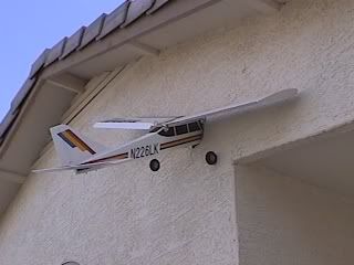
Ready to destroy some propellers.

feigao05.jpg


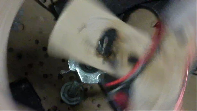
Then we discovered the wires were not inserted in the case for stress relief, but merely hanging off the magnet wire.

feigao06.jpg


The previous one was 5400kV & slightly heavier.

feigao07.jpg

feigao08.jpg
  Definitely changes the battery position.  Buying the same motor from the same store definitely brings us back to the beginning of M.M..


feigao09.jpg


The 1st problem was the fact that the prop adapter only tightens when spinning counter clockwise.  To act like a pusher, it needed to spin clockwise, loosening the nut.  We have threadlock poured in a small reservoir on the nut.  This has actually been holding.

feigao10.jpg


Some ideas for balancing it have come to mind.  Finding the center of wing pressure is the bigger challenge.

feigao11.jpg
  Zip tie landing gear is the new thing.
  Finally, there were experiments in more stable takeoffs.  The takeoff needed to be vertical for anything else to work.  Nothing takes off vertically.  Everything wants to kick to the side.

spindle01.jpg

The best weapon was a very large hole & a longer spindle.  The large hole would let it settle wherever the small changes in the center of gravity were.  The longer spindle would keep it stationary after flight speed was reached.


spindle02.jpg

High speed video showed it didn't settle on the center of gravity, but got pulled to whatever edge the COG was closer to.  Even if the COG was in the middle of the hole, it always pulled to the nearest edge with enough force to move the spindle.

No idea why this was happening.

spindle03.jpg


Attention turned to the spindle.  Now we have flexing going all the way to the base.  The closer it gets to lifting off, the more compliance the rod gives.  Theoretically, it should be spinning closer to its COG than ever.

takeoff01.jpg


That gave a pretty straight takeoff, compared to before.  Some gain tweeking got the altitude a lot more stable.  There is still an undershoot right after takeoff, but after that, it's very stable.  There was a time on the golf course, when we thought we would never get the takeoff profile tight enough to fit indoors.

Trying to control attitude in flight seems hopeless.  After takeoff, there is too much variation in camera angle to get a useful orientation.  Still pretty insane stability, compared to years ago.

turnigy01.jpg


For the 1st time in 3 years, we got something we ordered from hobbyking, using the cheap shipping.  It took 3 weeks.  These ended up 7 grams heavier than our lightest 800mAh & slightly bigger than the old battery & we only have 2 Dean connectors.

turnigy02.jpg

turnigy03.jpg

turnigy04.jpg


A few sparks & a whiff of ozone later.

gaui.jpg


The Turnigies were 7 grams heavier, but the Gaui we had since 2009, before Gaui ever sold a quad copter, is 8 grams heavier than our lightest 800mAh.

The Turnigies came at 1/2 charge.


stencil04.jpg


After proving hovering, Marcy 1 got a major overhaul.

stencil05.jpg

stencil06.jpg
It begins with a new wing.
feigao12.jpg


The electronics are shifted to the end & a 3 gram heat sink is installed.

marcy1_47.jpg


After all that weight shifting, it was more unstable than before.  

marcy1_48.jpg
  It could be the center of wing pressure or the angle of attack.
  Anyways, also noticed this motor wasn't powerful enough to do the job.  It had enough kV but not enough wattage.  The successful tests were at 0.5m, but it couldn't sustain 1m in altitude.  As it heated up, its power decreased until the cyclic had reduced effectiveness.  That seemed to cause it to lose control.
  2 minute flights are probably good enough.  A smaller battery might help.  Wouldn't know what to do with the last 6 batteries.


$16 of gas, $2 of taxes, & $22 of batteries later,


hyperion01.jpg


hyperion02.jpg


When the more energy dense motor is no longer made & you don't have enough room to fly a bigger wing, a smaller battery is the only choice.

They were both unbalanced.  1 was slightly puffed.  1 cell had 2.8V.  Another cell had 0V.  Still using a junk charger from 6 years ago, we had to charge 1 cell at a time, start it charging 2 cells, then quickly switch it to the low cell.  They advertize a 5C charging rate & we've had these up to 2C charging.


More autonomous flights proved the battery was a success.  It reduced the coning angle & increased stability.  Here we have 1 flight at .5 meters & 1 flight at 1 meter at 2x speed.  The motor overheated at around 3 minutes, causing a rapid descent in the 2nd flight.


throttle01.png


Telemetry from the flight in ground effect shows throttle increasing but not getting out of control.


throttle02.png


In the flight out of ground effect, throttle got exponential near the end & control authority decreased as the motor overheated.


Read more…

Getting the Nova ready for FPV


This week I focused on getting the Nova ready for the FPV system I'll be installing, and it flew great!I added a new wing that has a larger wingspan (62in.) and better locations for the ailerons (closer to the wing tips for greater leverage). This added a little more stability, slowed the airplane down a little, and allowed for the additional weight.


I also tested the wing loading by using the heavier battery (a 4.4Ah battery that weighs in at 12oz) and 4oz of extra dead weight to simulate the FPV gear that will be added next week.


Lastly, flying it in heavy wind (10-12 mph) was a pretty good test of it's general strength and stability. It handled it very well, and has inspired me to get some stabilization to help me out.


So far so good! Can't wait to FPV maiden the Nova!

Read more…

A Date with Ms. Purple (APM2)

Some interesting videos of my morning flights with the latest firmware and APM2.

Dont forget to watch the last video ;)

1st loiter

Arducopter, now with REAL chicken sound effects...
Loiter worked quite well considering the drift issue...
It only started to drift after a while.
Seems like the more stick input you give, the worse the drift gets.]

2nd loiter It went better, I tried to stay away from using too much stick.


1st alt hold. Went beautifully, as good as the sonar! Still the drift issue in stabilize.

low level alt hold
Pool noodles rock!

Karlas first attempt
I suppose I should fix the drift issue before I let my GF fly it...
Fortunately I was controlling the throttle and trying to film.
Funny as hell! It landed on the roof...


SUMMARY:
Loiter and Alt Hold work fine. But the drift issue makes it un-flyable!
The only thing that fixes the drift issue is resetting the board.
Then it works for 20-30s and then cant fly it anymore.
Running the level command and in-flight leveling doesnt do sh*t.

:)

Read more…
Developer

DISCLAIMER: This could be dangerous and might crash your copter.

OK! I made some new changes to the autotuning algorithm and I have tested it again in the simulator. I think this is ready for some real world testing from some VERY BRAVE users, or some simulation testing. Unfortunately I do not own a quad and my octo is out of commission until Tuesday, or I would be testing this right now outside.


First, here is what is new:

1. The amount of change applied to the P gain scales down with each iteration. This allows for quicker acquisition and better resolution of your Pretty Good Gain

2. If the tuning logic moved the P gain in the wrong direction it will revert to the best P gain that had been found and use that as the new launching point which should save some iterations

How to use it:

1. Replace the files in your ArduCopter 2.2b2 code base with the files that I have included in the .zip.

2. Upload the code to your board and test in the simulator so that you can get a feel for how it works (follow the same steps below for setup starting at step 5)

3. Update the config file to disable the HIL setting or change your frame type, etc...

4. Re-upload the code for live flight IF YOU DARE

5. Connect the APM to the Mission Planner.

6. Go to the configuration tab and manually set the CH7_OPTION to 8 as seen below and click "Write Params"

3689442072?profile=original

7. Set your Integral (I) gains for pitch and roll to zero and click "Write Params"

8. Bring the copter to a hover and flip CH7 to the high position to activate the auto tuning mode

9. Roll to the right or left and quickly return the stick to the center position. (Repeat this step at least 5 times)

10. Deactivate auto tuning mode by flipping CH7 to the low position

11. Reactivate auto tuning mode by flipping CH7 to the high position

12. Pitch the copter forward or back and quickly return the stick to the center position. (Repeat this step at least 5 times)

13. Deactivate auto tuning mode by flipping CH7 to the low position

14. Go to the configuration tab of the Mission planner and click "Refresh Params" to see your new tuned P gains

15. Write those values down.

The idea of steps 9 and 12 is to introduce a wobble and let the copter try to even itself out. Don't go too aggressive with your pitch or roll... again its just to introduce a disturbance.


My videos are in 1080p so that you will be able to read whats on the screen.


Questions, comments, discussion is welcome and encouraged!

Autotuning_AdamRivera_01202012.zip

Read more…

FPV in Maldives

FPV is the greatest way to discover places while you're on vacation. In the next few weeks and months TBS is going to present a couple of vacation videos ... here's the first from the Maldives, piloted by RiSCyD.

Read more…
Moderator

New colour night vision camera

flirtau.png

If you have quite a wedge of loose change down the back of the sofa this might be a fun thing to purchase!

Those long evenings hiding in a tree now in colour!


The Tau CNV color and monochrome cameras deliver near starlight-level imaging and are designed for security, military EO systems, hyperspectral imaging, and traffic monitoring applications. The CNV operates on less than 4 Watts of power, weighs less than 175 grams, and takes up approximately 150cm of volume.

press release here

Read more…
Developer

ArduCopter PID Autotuning - FOR SIMULATION ONLY

Hello all,

First, THIS IS EXPERIMENTAL FOR SIMULATION ONLY. Video coming shortly of me using it in the simulator.

I have a functional first attempt at automatic P gain tuning. I'm calling it Pretty Good Gains (pun intended). There is definitely room for improvement, but here is how it works:

PID controllers usually end up with an output graph that looks something like this (from wikipedia):

Change_with_Kp.png

As you can see by the above graph the most well tuned P gain value in this controller is 2. Why? Because it arrives at its target value the fastest with the least amount of overshoot and oscillation. One can see this in practice when flying a multi-copter and the PIDs are too high producing an oscillation. I have read a lot of different PID tuning strategies looking for something that I could replicate in code. I came across something called the Good Gain Method. Essentially this method of tuning requires the user to set the Integral and Derivative gains to zero and first focus on the P gain. Adjust the P gain until the least amount of oscillation is seen with an acceptable arrival time at the target value. If the P value is too low, the curve will take too long to get to the target and if the P value is too high you will see the more violent oscillations.

How do we do this in code? Well, first I require the user to input a disturbance into the system (ie. pitch right) and then wait for the user's input to return to zero (center stick). Now we have our starting point (the disturbance) and our target (zero pitch, or stable hover). As the copter attempts to return to a stable hover the error values follow a path similar to the curve above. As this is happening I measure the distance between the first peak and the first valley of that curve and how long it took to produce that peak and valley. Now we have our starting point. When another disturbance is introduced we can compare its peak/valley to the previous oscillation and decide which direction to move the P gain. Once that is done enough times, the P value is tuned.

Right now I move the P gain value in increments of 10%, but I can see changing that to adapt to the degree of the oscillation with increasing granularity as the P gain improves. I have tested this in the HIL simulator and it seems to work well. It works best if you set the P values a bit too high and let the auto-tune lower it.

I am attaching a zip of the files I modified. Please give me feedback and discuss my method. Again, Pretty Good Gains means that this isn't perfect. It also doesn't address the Integral gain... but I have plans for that too.

AutoTunePatch_AdamRivera_01192012.zip

Read more…

How Fast Can You Fly Without Crashing?

plane_crash.jpg

A professor at MIT developed an equation to determine the fastest theoretical air-speed for obstacle avoidance.

From Science Blog:  "Emilio Frazzoli, an associate professor of aeronautics and astronautics at MIT, says knowing how fast to fly can help engineers program unmanned aerial vehicles (UAVs) to fly at high speeds through cluttered environments such as forests and urban canyons.

Most UAVs today fly at relatively slow speeds, particularly if navigating around obstacles. That’s mainly by design: Engineers program a drone to fly just fast enough to be able to stop within the field of view of its sensors.

Frazzoli and PhD student Sertac Karaman developed mathematical models of various forest densities, calculating the maximum speed possible in each obstacle-filled environment.

The team’s work establishes a theoretical speed limit for any given obstacle-filled environment. For UAVs, this means that no matter how good robots get at sensing and reacting to their environments, there will always be a maximum speed they will need to observe to ensure survival."

Read more…

Ardustation Mega with Graphic LCD

3689442010?profile=original


I’d like to share my latest hardware ground control station. I call it the ArduStation Mega.

It retains all the features found on the DIYDrones Ardustation, as well as my Ardustation Uno but with some very important upgrades.
 
3689441965?profile=original
 
Notably the main processor has been upgraded to an ATmega2560 giving 8 times the size of both flash and ram, amongst other things :)

Also there is a graphical LCD that should provide a larger, more user friendly display.

The extra serial ports (4 in total) will enable future expansions as and when required. One is dedicated to the USB for loading software as well as potentially being used to allow a computer to share the installed Xbee.

If you don’t want to use an Xbee, or want to use more than one, that’s fine- three of the serial ports are broken out to the left of the board. These could also be used for adding a GPS unit, or perhaps a bluetooth to pc link for example.

Also broken out is the i2c port, so you can link it up to a magnetometer if need be (could make for simpler antenna tracking alignment)

A micro SD card will allow data logging, parameter saving, mission uploading and hopefully more!

3689442023?profile=original
The rotary encoder (like a radio’s jog dial) should help with faster navigation / value editing. The buttons are also on a separate PCB such that they can be mounted flush with the display or separately subject to enclosure constraints. (Also this means I can change the layout of the buttons)

The battery supply and Xbee RSSI are connected to give health information on voltage and telemetry link signal strength. Additional analog pins are also broken out for monitoring external sensors.
 
The PCB has been sized to match the dimensions of the LCD, giving a neat install that can be attached with screws and spacers. All of the components are mounted on the inside as well, such that the total unit size is minimised.
 
3689441987?profile=original
As with my Uno version, I use a single cell LiPo for the battery source, with an efficient step up regulator for the 5v supply. There’s also inbuilt USB charging.

The antenna tracking will be achieved by the two servo headers on the right hand side of the board. These also have a solder jumper for selecting off-board power in case heavy duty servos are to be used.

Please let me know what you think!


If you want to see more, here's a video of me showing it off:
 
 
Read more…

Get your own balloon mapping kit

IMG_0604

The same group (http://grassrootsmapping.org) which organized a citizen mapping of the BP oil spill is offering their DIY balloon-mapping kit as a reward in their Kickstarter campaign, which ends on January 30th. Having formed an DIY, open-source environmental science movement called Public Laboratory, they're now making open source hardware & software, and have grown to a movement of hundreds of people. $85 gets you a balloon kit, and their open source web-based map stitching software helps you convert your aerial images into an online map. There's even an infrared hack to take aerial infrared photos: http://publiclaboratory.org/tool/near-infrared-camera


Link: http://www.kickstarter.com/projects/1775485688/balloon-mapping-kits

Read more…

XMEGA AP's and ESC's

This is my first blog here so just few words about me:  I’m an electronic engineer, I'm from Romania and my hobby is obvious.

By more than one year now, I spent lot of time working with Atmel XMEGA family. My first autopilot with XMEGA 128A1 had external 16bit ADC (ADS8344) because at that time, internal 12bit ADC and DMA were still unclear to me. MPX pressure sensors for air speed and altitude, HMC5843 compass, ADXRS610 gyros and LIS344 accelerometer.

3689440861?profile=original3689440920?profile=original

This video is during flight testing of above mini-quattro:

Same AP I used for one Hexa:

Mean time, getting more familiar with XMEGA, I decided to go forward. The second AP I made, had different design: separate PCB for sensors. Dedicated XMEGA128A1 PCB for sensors and dedicated XMEGA128A1 PCB for PID and GPS navigation. This way I wanted to avoid MCU speed limitations during testing of different sensor filters/navigation algorithms. The AP is made of 3 PCB's.

3689440828?profile=original3689440876?profile=original3689440899?profile=original3689440962?profile=original

From top to bottom:

 -Analogical PCB is using LIS344 accelerometer, IDG500/ISZ500 gyros, HMC5843 compass and BMP085  absolute pressure sensors. The PCB have 94% of area covered by ground plane. Dedicated reference low noise IC with RLC voltage filter. All gyros and accelerometers outputs passing through 2nd order active Sallen Key low pass filter. Cut off freq.  is 75Hz for gyros and 10Hz for accelerometers.

-Next PCB has XMEGA128A1 at 40Mhz (40MIPS). Separate power supplies  for analogical and digital sides, each power supply IC having its  own RLC voltage filter at input. To keep conversion speed as high as possible, gyros are connected to ADCA and accelerometers to ADCB.  Both ADCA and ADCB can be triggered practically in the same time, each of ADCA and ADCB having 4 channels and because this is a  pipeline ADC (see XMEGA manual), 8 separated inputs can be sampled and converted in almost same time. ADC’s are running at 1.25MHz. This configuration will run 7 state EKF at 350Hz for time update and 300Hz for measurement update. Complementary filter with integer numbers is running at 2600Hz.

One I2C channel is used for HMC5843 and one hardware UART for serial communication with navigation MCU.  Serial com is at 500Kb/s and is using DMA transfer triggered at 2.5KHz. Several pins are directly connected to navigation MCU and used as  I/O flags in program. UART for PC comm. with DMA transfer (for logs and firmware update). There is also analogical input for temperature sensor from IDG500 (for temperature compensation).

-Last PCB is using  XMEGA128A1 at 40MHz (40MIPS), having also separate power supplies for analogical and digital sides with separate RLC voltage filters. All of the MCU’s and sensors supply IC’s are feed  by 6.5V switching mode power supply (TSR 1-2465). This way, dissipated power is kept at minimum. There is another 5V switching mode power supply (TSR 1-2450) used for GPS, R/C receiver, XBEE, SONAR and two small servos for camera .  All I/O are using dedicated hardware:

-  battery voltage monitoring

 - 8 PPM R/C inputs

- 8 PWM outputs (max 495Hz) better than 14bit resolution

- 2 PWM outputs for servos (camera control)

- I2C input for BMP085 from analogical card

- UART for PC comm. with DMA transfer (for logging and firmware update)

- UART with DMA transfer for GPS with activity LED

- UART with DMA transfer for XBEE with activity LED

-UART with DMA transfer for SONAR with activity LED

- Analogical 12bit input for SONAR

- 8 digital outputs at 500mA/each (ULN2803) for Buzzer, external LED’s and payload trigger

-2 ADC inputs 12bit resolution

-4 general purpose I/O used also as additional UART, PWM I/O or I2C

- one red LED for different status signalization

3689440938?profile=original

Below is one test flight with one oktokopter ( I had to buy the frame because at that time I did not had yet my own CNC machine ):

Last AP with XMEGA I made, is one PCB only. I wanted to make one multicopter where all electronic parts are kept between the two carbon fiber plates which are fixing the ALU arms and all cables to pass inside  ALU arms. This way copter is looking simpler, there is no need for canopy and electronic circuits are well protected. MCU used is XMEGA128A1 at 40MHz.

3689440849?profile=original3689440983?profile=original3689440998?profile=original

Same ADC configuration was used as previous AP, but with simple 1st order low pass RC filter  for gyros and accelerometers; LIS344 accelerometer, IDG500/ISZ500 gyros, HMC5843 compass and BMP085 abs. press. sensor. Analogical input for temperature sensor from ISZ500 (for temperature compensation). Following are the I/O’s dedicated hardware:

- battery voltage monitoring

- 6 PPM R/C inputs

- 8 PWM outputs (max 495Hz) better than 14bit resolution

- 2 PWM outputs for servos (camera control)

- separate I2C channels for BMP085 and HMC5843

- UART for PC comm. with DMA transfer (for logging and firmware update)

- UART with DMA transfer for GPS with activity LED

- UART with DMA transfer for XBEE

-UART with DMA transfer for SONAR

-2 general purpose I/O used also as additional UART, PWM I/O

Following are two BLDC ESC’s made with XMEGA16A4 at 40Mhz. First ESC I made did not had current reading but for second one, 0.005Ohm shunt was added together with smaller size MOS transistors.

First type ESC:

3689441021?profile=original3689441046?profile=original

The pictures below are for type2 ESC with shunt resistor; Motor and battery cables are in same side making easier connection inside frame:

3689441076?profile=original3689441093?profile=originalFeatures:

The ESC is using special hardware output for BLDC motor control from XMEGA (with AWEX extension).

The PWM freq. is  20KHz with 1000 steps between 0 and max PWM. One ADC channel running in free mode at 1.25Mhz with DMA transfer configured as differential input is used to read the current passing the shunt resistor. By reading the current have few advantages: improved starting up, limit of the maximum desired current, checking integrity of MOS transistors/motor coil and cable connection between motor and ESC during initializing at power up .

Command to the ESC can be send by any of PPM input, I2C or UART .

Two LED’s (red and blue) for error/run signalization. 

Rotor stall detection.

Few pictures of the copter with all electronic parts "inside" :

3689441129?profile=original3689441182?profile=original3689441208?profile=original3689441199?profile=original3689441233?profile=original3689441316?profile=original

Here is one video taken during initial PID testings. The ESC’s are of type2   with XMEGA16A4:

Work in progress is for one Hexa Y frame also with all electronic cards between the two CFK plates:

3689441258?profile=original3689441335?profile=original

3689441284?profile=original

Last video is with one 3m wingspan airplane during first flight test. Engine used is ZENOAH 68cc. When Spring will be back, will start testing this platform with AP and keep you posted.


Regards,

Sergiu

Read more…

JETPAX Quad frames.

Quad is made from a combo of fusion plastics and carbon fibre.

This is a parts and build video of the frame

i will be continuing to test this frame out crashing it dropping it and other crazy flying mishaps that happan when you fly quads.

this frame is only for the open source community
JETPAX want to give back to the open source developer with this great durable

Quad/Octo Frame

Read more…
Developer

Here a video about the HIL tests of the firmware ArduCopter v2.2 b2xp2 (with JLN updates) with an Helicopter in H1 mode (Raptor 30 type) on the AeroSIM-RC simulator.

The tested features are:

- STABILIZE mode,
- LOITER mode (GPS position Hold),
- RTL (Return To Launch),
- AUTO mode (GPS autonomous navigation),
- AUTO TAKE-OFF,
- AUTO LANDING.


Tested with AeroSIM-RC v3.81 and an ArduMega 2560 (APM1) through the APM mission planner v1.1.20.

This is an alpha version of the firmware and only for explorers and testers....

Transmitter: Turnigy 9x, Receiver: Turnigy 9x8Cv2.
Helicopter model simulation (type Raptor 30) with 1 roll servo, 1 pitch servo, 1 cyclic servo (type H1).

More infos at: http://diydrones.com/profile/JeanLouisNaudin

Read more…

Hi,

I changed the attitude control loop a little bit to achieve more stability. Rate control with a PID(T1) instead of a PI controller. Here I present the necessary changes in the code to do this.

Pro:

  1. Much more attitude stability
  2. Much faster response on disturbances or new setpoints

Con:

  1. You need to tune the control loop again after this change
  2. This change is experimental, it works for me but you do it on your own risk ;)


I'm starting from Software AC 2.1. First I modified the library "PID" to save calculating time. I saved the following floating point operations per call to "get_pid": 2 x division, 4 x multiplication. You can download the modified library here. Unzip it and put the folder "PID_fast" in the "libraries" folder.

In file "ArduCopter.pde":

Add this line to the includes:

#include <PID_fast.h>            // PID library

For the following 4 blocks, I post it like the diff you get in GIT. The "-" means that you should look for this line and remove it. Replace it with the following lines starting with the "+". Of cause, the lines in the code have no "-" or "+". It's just to show what to remove and what to add instead.

-                g.pi_rate_roll.reset_I();
-                g.pi_rate_pitch.reset_I();
+                g.pid_rate_roll.reset_I();
+                g.pid_rate_pitch.reset_I();

-            g.pi_rate_roll.kP(tuning_value);
-            g.pi_rate_pitch.kP(tuning_value);
+            g.pid_rate_roll.kP(tuning_value);
+            g.pid_rate_pitch.kP(tuning_value);
 
-            g.pi_rate_roll.kI(tuning_value);
-            g.pi_rate_pitch.kI(tuning_value);
+            g.pid_rate_roll.kI(tuning_value);
+            g.pid_rate_pitch.kI(tuning_value);
 
-            g.pi_rate_yaw.kP(tuning_value);
+            g.pid_rate_yaw.kP(tuning_value);

In file "Attitude.pde":

In function "get_stabilize_roll(int32_t target_angle)":
 
-    rate         = g.pi_rate_roll.get_pi(error, G_Dt);
+    rate         = g.pid_rate_roll.get_pid(error, G_Dt);

In function "get_stabilize_pitch(int32_t target_angle)":

-    rate         = g.pi_rate_pitch.get_pi(error, G_Dt);
+    rate         = g.pid_rate_pitch.get_pid(error, G_Dt);

In function "get_stabilize_yaw(int32_t target_angle)":


-        rate     = g.pi_rate_yaw.get_pi(error, G_Dt);
+        rate     = g.pid_rate_yaw.get_pid(error, G_Dt);

-    rate         = g.pi_rate_yaw.get_pi(error, G_Dt);
+    rate         = g.pid_rate_yaw.get_pid(error, G_Dt);

In function "get_rate_pitch(int32_t target_rate)":
 
-    target_rate = g.pi_rate_yaw.get_pi(error, G_Dt);
+    target_rate = g.pid_rate_yaw.get_pid(error, G_Dt);

In file "Parameters.h":

Increase the number after "static const uint16_t k_format_version" by one. Warning: This will make the APM erase your EEPROM and Log after flashing the new compiled firmware. So save your settings first! After this, you have to reload your settings and level the copter again.

Later on in the file:

-    k_param_pi_rate_roll = 235,
-    k_param_pi_rate_pitch,
-    k_param_pi_rate_yaw,
+    k_param_pid_rate_roll = 235,
+    k_param_pid_rate_pitch,
+    k_param_pid_rate_yaw,

-    APM_PI        pi_rate_roll;
-    APM_PI        pi_rate_pitch;
-    APM_PI        pi_rate_yaw;
+    PID_fast    pid_rate_roll;
+    PID_fast    pid_rate_pitch;
+    PID_fast    pid_rate_yaw;

-    pi_rate_roll        (k_param_pi_rate_roll,            PSTR("RATE_RLL_"),    RATE_ROLL_P,        RATE_ROLL_I,        RATE_ROLL_IMAX * 100),
-    pi_rate_pitch        (k_param_pi_rate_pitch,            PSTR("RATE_PIT_"),    RATE_PITCH_P,        RATE_PITCH_I,        RATE_PITCH_IMAX * 100),
-    pi_rate_yaw            (k_param_pi_rate_yaw,            PSTR("RATE_YAW_"),    RATE_YAW_P,            RATE_YAW_I,            RATE_YAW_IMAX * 100),
-
+    pid_rate_roll        (k_param_pid_rate_roll,            PSTR("RATE_RLL_"),    RATE_ROLL_P,        RATE_ROLL_I,        RATE_ROLL_D,        RATE_ROLL_IMAX * 100),
+    pid_rate_pitch        (k_param_pid_rate_pitch,        PSTR("RATE_PIT_"),    RATE_PITCH_P,        RATE_PITCH_I,        RATE_PITCH_D,        RATE_PITCH_IMAX * 100),
+    pid_rate_yaw        (k_param_pid_rate_yaw,            PSTR("RATE_YAW_"),    RATE_YAW_P,            RATE_YAW_I,            RATE_YAW_D,            RATE_YAW_IMAX * 100),

In file "config.h":

You have to add a few lines. Lines to add are indicated by "+". Other lines are for reference to find the right place.

 #ifndef RATE_ROLL_I
 # define RATE_ROLL_I         0.0
 #endif
+#ifndef RATE_ROLL_D
+# define RATE_ROLL_D         0.0
+#endif

 #ifndef RATE_PITCH_I
 # define RATE_PITCH_I        0 //0.18
 #endif
+#ifndef RATE_PITCH_D
+# define RATE_PITCH_D         0.0
+#endif

 #ifndef RATE_YAW_I
 # define RATE_YAW_I     0.0
 #endif
+#ifndef RATE_YAW_D
+# define RATE_YAW_D     0.0
+#endif

In file "system.pde":

-    Log_Write_Data(12, g.pi_rate_roll.kP());
-    Log_Write_Data(13, g.pi_rate_pitch.kP());
+    Log_Write_Data(12, g.pid_rate_roll.kP());
+    Log_Write_Data(13, g.pid_rate_pitch.kP());

Now, all changes are done. Now save your current settings of the APM, compile and load the code... You will find 3 new parameters (RATE_RLL_D, RATE_PIT_D and RATE_YAW_D) you can edit like any other mavlink parameter. These are the D-Terms for all rate control loops.


Testing and tuning:

Be really carefull, propellers are dangerous!  I do the tuning of the control loops while I hold the copter in my hand and try if it compensates the disturbances without overshot or oscillation. You should decide for yourself if cou can hold your copter in one hand while you throttle up and test the stability. Even small propellers can harm your fingers! If you want to proceed, I do it like this:

  1. Reload your last setup and level the copter.
  2. Set all parameters for stabilize STB_***_P and STB_***_I to zero.
  3. Set all parameters for rate control RATE_***_P, RATE_***_I and RATE_***_D to zero.
  4. Hold the copter with one hand, throttle up until it becomes weightless, then turn it. Nothing should happen, because all control loop parameters are zero. You have just manual throttle control.
  5. Increase the D-Terms and test again while holding the copter in your hand. Remember, it can't fly with most parameters set to zero. Increase the D-Term and test again, until you got some oscillation. Let's call the value you found 100 percent. Now reduce it to 50..70 percent. Do this for ROLL and PITCH.
  6. Proceed with the P-Terms. Increase and test until it gets unstable. Then reduce it to 50..70 percent of the original value.
  7. Set the I-Terms to 30..50 percent of the P-Terms. Test again. If it is unstable, reduce P and I and maybe D a little bit.
  8. Now go to the STABILIZE control parameters. Increase the P-Term. Now the copter should return to level position automatically. Increasing of the P-Term will lead to a faster return to level position after disturbance or also to a fast respond to the desired angle by pilot input. Find a value where the copter returns fast from a disturbance without overshot or oscillation.
  9. Always leave the STABILIZE I-Term STB_***_I zero in this controller configuration!
  10. For YAW you can leave the D-Term zero and use your previous settings for STABILIZE and RATE control. Or you tune it, but I didn't try it at YAW yet.
  11. If everything works well and the copter returns to level position after disturbance or pilot input without overshot or oscillation, then you can try to hover and fly carefully. Not before!

Here are some controller parameters from my Tricopter (80 cm from motor to motor, 1440 g in flight weight), the D-Terms are quite small:

STB_PIT_I,0
STB_PIT_IMAX,1500
STB_PIT_P,9
STB_RLL_I,0
STB_RLL_IMAX,1500
STB_RLL_P,9
STB_YAW_I,0
STB_YAW_IMAX,1500
STB_YAW_P,4

RATE_PIT_D,0.015
RATE_PIT_I,0.02
RATE_PIT_IMAX,1000
RATE_PIT_P,0.09
RATE_RLL_D,0.012
RATE_RLL_I,0.02
RATE_RLL_IMAX,1000
RATE_RLL_P,0.09
RATE_YAW_D,0.004
RATE_YAW_I,0.002
RATE_YAW_IMAX,500
RATE_YAW_P,0.5

It would be really nice, if other people try this modification. For me, it was a significant increase in stability.

Regards, Igor

Read more…

1st Octo Flight

3689441864?profile=original3689441685?profile=original

I finally worked up the balls to fly the thing!
Im quite impressed that it actually flew and didnt just explode on the spot after arming the motors ;)

A little wobbly, but thats more me and the shaking than anything else.
Slight drifting, however I havent done the whole in flight leveling thing.

Firmware 2.2b2 Octa. Default PIDS.
So need to tune them! Any Octo guys have some pid suggestions? (What should I change?)
Im definitely looking for sluggish movement for taking photos/videos. I dont need any aerobatics.

As far as power goes, the whole time, i wasnt using more than a 1/4 throttle, even for lift off.
It did bob up and down a bit, thats also coz my TX throttle is a little stiff...

Yaw was perfect :)

All in all, it was a successful test flight! Especially since the last thing i built and flew was the
arducopter. Going from something that weighs 1.5kg with +-3kg of thrust.
To a MONSTER that weighs 4.7kgs with +-20kgs of thrust, is quite intimidating to say the least!

This is definitely a testiment to my engenuity, and most of all an absolutely SUPERB autopilot!

Next job, PID tuning!

Till then!

G:)


Read more…

3689441787?profile=original

Dear all,

DISCLAIMER: I hope I do not bend the forum rules too much by this blog post and would hate to offend the community by starting the discussion of a (at least marginally) political topic. However, since in the past also UAV regulatory developments and issues that relate to the open-source community have been discussed, and since I believe this topic is highly relevant to the diydrones community, I decided to go ahead.

Those of you who have been visiting wikipedia, google, or some of the other sites that participate in the SOPA/PIPA blackout today may have noticed that parts of the private and public web communities have decided to virtually demonstrate against these (sets?) of law proposals. I myself, being located inside Europe, don't think I can completely follow the legislative process and the actual implications of SOPA/PIPA. However, it seems obvious to me that this topic is very relevant to diydrones as a site of open information exchange. I would like to raise awareness here and ask those who actually are located in the US and can influence the vote by contacting their representatives to please inform themselves and consider (as google's picture says) to take action. Please check out:

https://www.google.com/landing/takeaction/

http://en.wikipedia.org/wiki/Sopa   (the only wikipedia page that seems to work today)

http://yro.slashdot.org/story/12/01/18/0834219/ask-slashdot-what-can-you-do-about-sopa-and-pipa

Thanks!

Read more…