All Posts (14048)

Sort by

ADXRS453 Gyros with Ultrahigh vibration rejection

I just got 3 pcs. ADXRS453 gyros from Analog Devices ( Farnell price was 100US$ for one piece.)

3689443399?profile=original

  I added also one ADXRS610 in the picture to compare the size of the gyros. As you can see it can be connected vertical for pitch/roll  or horizontal for yaw.This is from data sheet:

±300°/sec angular rate sensing
Ultrahigh vibration rejection: 0.01°/sec/g
Excellent 16°/hour null bias stability

Internal temperature compensation
2000 g powered shock survivability
SPI digital output with 16-bit data-word Low noise and low power 3.3 V to 5 V operation
−40°C to +105°C operation.

APPLICATIONS
Rotation sensing in high vibration environments
Rotation sensing for industrial and instrumentation applications

High performance platform stabilization.

"An advanced, differential, quad sensor design rejects the influence of linear acceleration, enabling the ADXRS453 to offer high accuracy rate sensing in harsh environments where shock and vibration are present.The ADXRS453 uses an internal, continuous self-test architecture."

Specifications like ultrahigh vibration rejection and internal temperature compensation were enough to trigger a flag from 0 to 1 inside my brain. So in less than one month I will have ready one autopilot with XMEGA and this promising gyros.

I will keep you posted about results.

Cheers,

Sergiu

Read more…
Developer

JSBSim Trimming Demo for F16 and Shadow UAS

A gui for JSBSim is demonstrated. The gui is capable of trimming any aircraft modeled in JSBSim at various flight conditions. It can simulate the aircraft at the calculated trim conditions, save the linearizations around these trim states, and output the linearization to a form readable by ScicosLab. The software is demonstrated on the standard f16 model included with JSBSim and a shadow UAV model, part of arkhangar. The linearized state space models output at the trim conditions are used to generate bode and root locus plots in ScicosLab.
https://github.com/jgoppert/jsbsim
https://github.com/arktools/arkhangar

Read more…

3689443330?profile=originalSimulated charging arrangement. Always use fireproof container for the batteries when charging!

I updated my charged to balancing one a while ago, but for some reason I didn’t buy one of those new multichargers, which pack a number of separate chargers in to one device. I use two 3S battery packs in parallel configuration on my plane and I have three sets of those. After a day of flying, charging six 3S packs separately is a long and laborious task. Since my charger can handle 6S packs, I thought why not to make an adapter cable to charge two packs at once. Since all the cells are rated the same capacity, charging 2x3S packs in essentially same than charging one 6S pack.

The following cables were build:

3689443412?profile=original

3689443456?profile=originalFirst adapter combines balancing leads from two packs to one connector. If you look closely, you can see that the ground wire is a little wriggly. When soldering the cable I did not think it all the way through and connected ground wires from both connectors together. When I connected the batteries, one of the ground wires vaporized with a loud pop. So be sure to leave second ground wire unconnected (pin 1 of the 2nd connector).

Second adapter is more obvious, it just connects the two packs in series. I suggest to number the battery connector which ground wire goes straight to the charger with number one and also the balancing connector which has ground wire connected as number one. These numbered connectors should be connected to same battery.

After connecting the batteries, set your charger to double voltage that the rated pack voltage (22.2v in this case) and charging current to the same as the rated charging current of the pack. It does not matter whether the packs are as empty or not, since the individual cells get balanced (although if there are big differences, balancing seems to take time at least on my charger). All that matters is that both packs have the same capacity and can handle the same charging current.

You can also make the same kind of adapters for 2S batteries, or even for the batteries more than 3S. The only limiting factor is that how many cells your charger can support at one time.

You can find schematics to adapters from my blog: http://antibore.wordpress.com/2012/02/02/charging-two-3s-li-po-packs-at-the-same-time/

Read more…

Flip, the tri

3689443352?profile=original

Once upon an idea...

okay, okay, you all know the great idea about building a convertible tri - to planecopter. Oh yes Avatar like, old story no news. However, I started to work on one. I am still far away from anything that is convertible, but it might be soon a flying tri.

I'm using APM v1 with the 2560atmega the oilpan, gps, sonar EZxx. The frame is made out of CFRB, re-enforced with honeycomb. The arms, about 36cm each, are made from titanium, with a cold coated wolfram-aluminum coating. The three motors, 750kV; NTM 2836; about 250W each on 4S 2200mA LiPo. The props are 12"4.5; CCW/CCW/CW. I use a digital servo to rotate one of the motors, but I've already the setup to turn each motor 90° fwd/aft. All together, including a bunch of stainless steel A4 grade bolts and sel flocking nuts, the tri is on 1.7kg. Heavy beast. If I replace the titanium arms with carbon fibre, I could save about 150g. My body is more or less two round carbon sheets, 20cm diameter. Way to much material, but - who cares. I use as ESC the HK Blue Series 30A. 


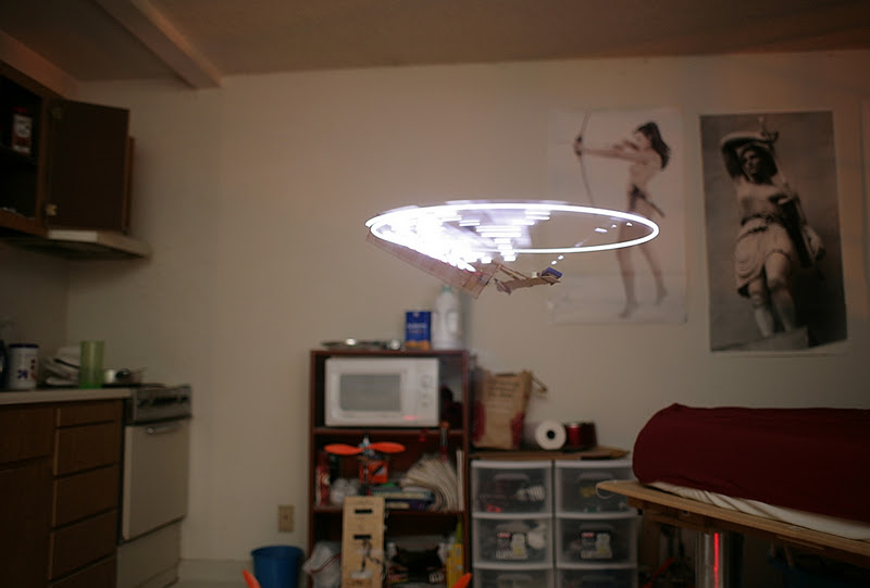
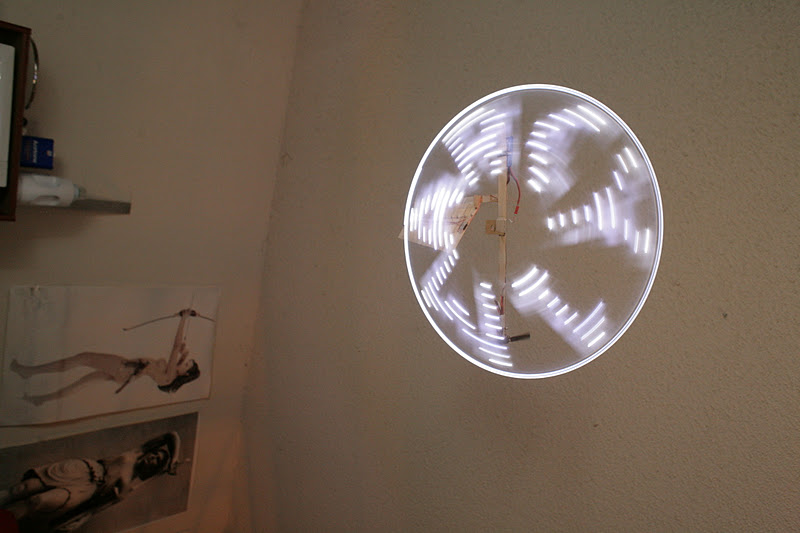
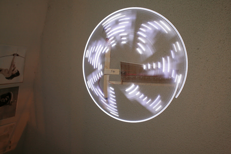
The pictures shows a partly disassembled tricopter. Troubleshooting... 


 The Firmware is now 2.2.6b. To reverse the yaw servo I had to change the fiftyHz loop in Arducopter.pde

 APM_RC.OutputCh(CH_TRI_YAW, ( (-1 * (g.rc_4.radio_out - g.rc_4.radio_trim) ) + g.rc_4.radio_trim ) );


Time for takeoff...soon. I've to find the best CoG - but I'm not completely sure on how exact the CoG must be - clearly, as good as possible,...but maybe a few mm off? Fine too? Who knows.


I had some troubles, most are solved:

*) Vibration due to loose turn table mechanic. Some preload on the bearings and the problems was solved

*) Vibrations caused by unbalanced blades. The CW blade (from Arducopter Store) had a nice inbalance. Trimming was necessary

*) Yaw servo reversed in auto trim. Solved it with entering the update line, see above.

*)  Took me a few minutes to figure out on how to load AC through Arduino. But finally easy.

*) Then was the little software updates when suddenly the YAW servo wasn't supported anymore (2.2b-2.2b5).

*) Too heavy, first I had two 2200Ah LiPoFe A123 6.6V in series. I've now one single LiPo 4S 2200Ah; reduced the weight about 150g.

*) Some flips because I connected the esc left/right reverse....STUPID I AM

*) Some flips because one ESC did not provide the same output power as the other one.....solved new ESC; I hope

*) Last but not least...working on the CoG.


3689443280?profile=original 

I use a 6 Channel TX/RX Skytech Ts6i. 


I hope I can lift of at about 60-70% throttle max. The next days will proof it. Then next step: full conversion. Mechanic is easy, but coding will take time.


Thanks for Igor and Don for support. 


Read more…

Make your own KickStarter style hexa!

12112011_v4H6_600_3.jpg

So there have been a few threads about the failed Kickstarter campaign by Kellie Sigler of LumenLab.com. Failed not because it they didn't collect enough money in the time alotted, but I'm assuming due to potential legal issues with selling a UAV to overseas buyers or a lack of originality in this project as they might have been designing and building nothing new or of their own design. There has been some discussion about if this project was actually a scam.

http://diydrones.com/profiles/blogs/apm-powered-hexacopter-project-on-kickstarter?id=705844

http://www.diydrones.com/profiles/blogs/kickstarter-drone-is-a-hoax?commentId=705844%3AComment%3A773491&xg_source=msg_com_blogpost

http://spectrum.ieee.org/automaton/robotics/diy/update-eye3-drone-officially-too-good-to-be-true

http://www.kickstarter.com/projects/eye3/eye3/comments

http://news.cnet.com/8301-17938_105-57369152-1/kickstarter-grounds-eye3-flying-camera/

Right now, I come down on the side of the project didn't include a single photo of their own work so I doubt they've even built one. They made claims about using "these computers" for 2 years when discussing the APM2 when I'm on the ArduPilot dev team and I don't even have one yet! And they had an estimated delivery date of March, 2012 without ever checking with Jordi and 3DR about delivery dates and quantities. Is this wrong? I think so. Is it a scam? I wouldn't call it that. But they sure don't keep their estimated delivery dates (see 8-10 months later) .


So what's the point of this blog? I just want to educate you on where you can go to get the exact parts listed in the KickStarter campaign and build your own.

Will it be easy? No.

Is it bullet proof? No.

Will you crash it? Yes!

Do I have the PID settings for this airframe? No.

Can I send you all the parts if you order from me? No. I'm not selling anything.

What exactly was I getting for the extra money on KickStarter? I would say packaging....and maybe a distribution board (they called it a "HOOK UP BOARD").

Have I built one? Nope.

Do I know what I'm talking about? Too soon to tell.


APM2: $199

Xaircraft Hexa Frame carbon fiber + Motors, ESCs and camera mount: $669

5000mah 3S lipo (they listed 6000mah but no voltage):  $26.72

Mission Planner Download:  $FREE 

Futaba T8FG Radio (but lots of other radios would work just fine):  ~$480

Turnigy 4x6S Lithium Polymer Battery Pack Charger:  $99 

X-Bee Telemetry Kit: $150


Total cost buying directly from the source: $1,624 + shipping.

They were going to include a "pro spares" kit (whatever that is) and a TX case for $2,499.

What's missing from the list above is PID tuning values and lots and lots and lots of trial and error.


EDIT: This photo may be the only evidence that Kellie and company may have actually built one!

Found here: http://kelliesigler.com/images/IMG_1147-1024x764.jpg

IMG_1147-1024x764.jpg

Read more…

Bixler/Sky Surfer EPO foam repair

3689443209?profile=original

The most recommended plane for a starting drone researcher is the Bixler or Sky Surfer (depending on what company re-branded the model).  These planes are all made of a foam material called Expanded Polyolefin "EPO".  A topic that most people that use EPO planes encounter is how to go about repairing crash damage.  I present for your consumption the boiling water method, which has been presented a few times before in RC group posts.

First, if we examine Figure 1 below it will be noted that my 2nd bixler has the characteristic front crumple zone damage associated with a nose in landing.

Figure 1

In order to repair this crash damage I prepared the apparatus pictured below in Figure 2.  This consisted of a 4500mL beaker, supports, and a Bunsen burner.  I also used an RTD senor to measure the temperature at specific points during the process  Conceptually, one could easily employ a standard boil kettle, but care should be taken as chemicals may potentially leach out of the foam during boiling, so if possible use a canning pot or other vessel that does not come into contact with foodstuffs.     

Figure 2 

3689443193?profile=original

Using this apparatus.  I determined that in order to re-expand EPO foam the required temperature is quite high ~90 Celsius.  I personally used 1 minute as my dip time, as I wanted to minimize the servos exposure to moisture.  Longer dip times might yield similar results at lower temperature, but I did not investigate these.  In order to check the temperature without a thermometer you could either wait for a rolling boil or dip a wing tip in the water for a minute and observe.  If you see the characteristic "pearling" or "lizard skin" pattern where the EPO pellets have expanded out after ~1 minute you are at the right temperature for your dip.  The horizontal stabilizer of my first bixler, which has been partially dipped is pictured below in Figure 3.  


Figure 3 

3689443224?profile=original

I dipped my planes nose into ~90C water and held it there for ~1minute until I could visibly see "pearling" thru the glass of the beaker.  I then removed the plane and attempted to foam safe CA glue the now de-stressed rifts back together.  The result is presented below in Figure 4.  

Figure 4

3689443043?profile=original

All in all, this method does work to some extent particularly for eliminating bent areas especially on the rudder, wings, and horizontal stabilizer, but it probably will not restore a plane to factory condition.    

Read more…

Swarm of Quads!

Latest Progress from the Folks at the GRASP Lab

Would love to see what flight control algorithm they're using on these things.

Great picture of the infrared lamps, at the end of the video:

kmel_nano_quads.jpg

Read more…

Kickstarter Drone is a Hoax

seal-of-fail.jpg

After receiving much attention over the past few days, the aforementioned Eye3 Drone project on Kickstarter has been officially pulled on account of photoshop shenanigans and overall shadiness.

From IEEE Automation Blog:

"At first glance, the eye3 drone seemed like an incredible deal. For US $2500, you could get yourself a beefy hexacopter capable of lifting over 6.8 kilograms (15 pounds) with an included autopilot that would take all of the hassle and stress out of flying the UAV...

People on the Internet, being people on the Internet, did some digging and found out several things. First, the pictures of the kit on Kickstarter are just pictures of this kit (from cnchelicopter.com) with the attribution photoshopped out. Also, the founders of eye3 allegedly owe a bunch of people money (or a product) on another project."

Read more…
3D Robotics

A quad with everything for less than $100

3689443076?profile=original

HobbyKing's done it again. Check out this deal: their mini-quad with four motors for $33.95! (Or $31.95 if you just let your browser sit open on that page for a few minutes). 

All you need to add to make a RC quad (in addition to your regular RC system and LiPo batteries) is:

That's $90 all told.  Now, in fairness, this is a pretty crappy little frame and it won't last past a crash or two. I also wouldn't expect too much outside in the wind. But what a great way to get started! 

Read more…

More Progress on the Quad Frame

3689443094?profile=original

I have just finished the first revision of my full frame.  The arms are designed to be very ridged in every bending moment.  I added anchor points to the arms about half way out.  This will allow me to attach stay wires that will also help keep the frame ridged.  The hub is designed to break at bolted connection to the arms in the event of a hard crash.  The hub has the fewest parts and would be easiest to replace.  The arms can fold together for compact storage.  The hole in the hub is designed to accept an electronics package.  The electronics package can be loaded and unloaded with a few simple screws.  This gives me flexibility to re-design with ease and produce several different arrangements for different missions.  There is also room to add a retractable landing gear set.  So far, the total weight comes out to be about 112 grams.  Progress is slow, but coming along as I have the time.

Read more…
Developer

A feature frequently requested is to add support to ArduPlane for using sonar to control the landing flare.The answer, unfortunately, is probably no.  Take a look at this graph I obtained yesterday...

3689443157?profile=original

This has been on my to-do list for ages as I have never gotten around to getting some real world data to see if this would work.  Finally got the real world data yesterday with the Maxbotix XL-EZ1 mounted in a SkyFun.

The graph shows data logged on a flight with 6 low passes using APM2 and the MaxBotix .  The standard ArduPlane/ArduCopter sonar library was used, including the 6 element mode filter (as recommended by MaxBotix.  The terrain over which the flight was flown was middle of the road in terms of difficulty for the sensor (in my estimation) being open arid prairie, with scattered clumps of low prairie grass   Based on the actual low passes the "good" altitude estimates (bottoms of the troughs) by the sonar were probably better than the equivalent altitude estimates by the baro sensor.  Unfortunately, as can be seen, when moving over the ground with significant speed the sonar fails to maintain a clean estimate of the altitude, even with the mode filter.

Of particular concern would be occasions such as during the second, fourth, and sixth pass, where the sonar suddenly reports a much higher altitude than actual.  If using sonar for flare control, this would likely result in a pitch down, with bad results.

Certainly under good conditions the sonar could be used for flare control, but it does not appear to give a robust enough estimate of altitude to be useful for general use.

Read more…

Marcy 1 with POV


A 3x2 propeller, another tuning of the PID & azimuth, & a lot of camera flashes got it up to 9 minutes. Previously, it was a 3x3 propeller. The motor stayed just cool enough.

flight35.png


Here, the battery hit 6.6V & started falling over.  Throttle started ramping up at that point.

Overheating still sometimes happens faster & it shows up as a throttle which diverges from battery voltage.

flight36.png


Here, the battery never fell over but was stable at 6.8V.  Throttle ramped up anyways, probably from motor overheating.

Meanwhile, it's a trip into history
pov01.jpg


as hardware from 2 years ago is recycled

pov02.jpg
into a new, much lighter, more reliable POV attachment.  The dust shows how long ago M.M. was.
The flight computer had to be rebuilt for the 1st time in 2 years.

Of note is a new etching technology seen on the Goog Tube.

etch44.jpg


Just float the board upside down on the FeCl.  Surface tension holds it up.  Slide it around to remove air bubbles & let it sit for 30 minutes.  The copper magically falls away as it's etched.  No need for heating, airating, stirring, or splashing FeCl in your eye.


etch45.jpg


Took 3 years of manual board etching to figure that out.


etch46.jpg


Magnet wire jumpers.
marcy1_board01.jpg


New & old, with conformal coating.
900mhz12.jpg


The 1st Marcy 1 board was made on Aug 25, 2009.
marcy1_13.jpg


The 2nd Marcy 1 board was made on Dec 30, 2009.
etch22.jpg


The 1 that consumed most of our time was made on Jan 12, 2010.  So that was a 2 year old board.

marcy1_board02.jpg
So this is our 4th Marcy 1 board.  As much as possible was recycled from the old board.  Working with this ancient hardware of course reminded us of the peak of M.M..  That really feels like the peak.  We don't feel nearly as attached to Her as we did in that time.
marcy1_board03.jpg

Rediscovered the hard way that 32Mhz isn't enough to drive the radio.  It needs the 64Mhz clock.

marcy1_board04.jpg


The full magnetometer is on the wing.  It only does 120 samples/sec.  At the nominal flight speed, that's 20 samples/revolution.

Moved the LED to the wing & did some POV trickery so it could detect attitude during the takeoff.  The POV doesn't seem to interfere with the machine vision.


pov07.jpg
  Tried using a red LED again for the machine vision, without any luck.  The drop in brightness throws it off even in darkness.  In daylight, the POV overwhelms it.  Anything is going to require white LEDs & differences in luminance.
The original Marcy 1 had the LED on the wing, which may also have improved the coning angle situation.


Disappointing that we never found a use for 3D sonar.  Only a large blimp or a ground vehicle could have used it.  Sonar overall is a mess.  We once envisioned a network of receivers on a ceiling, allowing a UAV to travel anywhere in a building.  It was way too directional & slow.


It could fly a blimp.  There was once a blimp based courier system in an HP building.  They used a robotic blimp to send pieces of paper between cubes.  All we've done is make it cheaper.

Video can now do the job much better.


The long flight times & experience with how long you can expect stable flight got us the 1st flash photos.

Surface mount LEDs would be nice, but we can't afford $20 of shipping for $1 of LEDs.
marcy1_50.jpg

marcy1_51.jpg

IMG_5796.JPG

marcy1_52.jpg

marcy1_53.jpg


marcy1_54.jpg

IMG_5790.JPG

marcy1_55.jpg


marcy1_56.jpg

marcy1_57.jpg


marcy1_58.jpg

pov03.jpg

pov04.jpg

pov05.jpg

pov06.jpg
 

There was also this video of the very 1st POV flights, with lousier tuning.

Read more…

Quad First flight

It took me a while to get to this point, Build log (in dutch) but now i am almost there. Yes almost, I've got myself a very strange arming procedure. But enjoy the video first.


Arming procedure:

  1. Connect copter whit USB to laptop.
  2. Let APM 2.0 Boot
  3. Connect Lipo (laptop crash if i do this)
  4. Hear 4 motors arm
  5. turn on the camera ;-)
  6. fly

If i don't follow this procedure i am getting only 1 motor to arm Not really the way to go but for me its not possible to find the solution. 


Read more…

QRM [DIY quadcopter] update 2

thumb.php?src=cache%2Falbums%2FProjecten%2FQuadcopter%2FPrototype+2%2FDPP_0177.JPG&size=450&ratio=OAR&save=1

This week all necessary parts for the QRM quadcopter arrived, and we test fitted them on the aluminum prototype frame. Everything fitted perfect, and we finalized the designs so that the frame could be machined out of carbon fiber.

 Together with the parts ordered at Hobbyking we bought a couple of 100x300mm 1.5mm thick sheets of carbon fiber. We managed to nest all the parts on two of these sheets, reducing the waist material to a minimum. When machining carbon fiber the material that is chipped away are minuscule fibers that you really don't want to inhale. (not often anyway) The parts could be machined using a vacuum cleaner, but we chose to make a bath in which we can machine the carbon fiber under water. This was done purely as a dust collecting mechanism, and not as coolant.

thumb.php?src=cache%2Falbums%2FProjecten%2FQuadcopter%2FPrototype+2%2FDPP_0167.JPG&size=450&ratio=OAR&save=1

thumb.php?src=cache%2Falbums%2FProjecten%2FQuadcopter%2FPrototype+2%2FDPP_0168.JPG&size=450&ratio=OAR&save=1

thumb.php?src=cache%2Falbums%2FProjecten%2FQuadcopter%2FPrototype+2%2FDPP_0169.JPG&size=450&ratio=OAR&save=1

As you can see above we tabbed the parts so that they wouldn't come lose while machining. Both sheets where machined on our home build CNC machine, with a 2mm spiral toothed solid carbide endmill, with a full-depth cut. Machining took about twenty minutes per sheet, and we recorded the whole process. The water got black almost instant, so the machining itself isn't viable. We fast-forwarded the movie, and cut out some parts. You can see the sheets being taken out of the bath at 1:40 and 3:00

After machining the parts, we started assembly. The video below is fast-forwarded, the real time was about one hour. The only thing left to do is to connect all the electronics, set up the control board and see if she flies!

The total ready to fly weight will be around 250 grams!

thumb.php?src=cache%2Falbums%2FProjecten%2FQuadcopter%2FPrototype+2%2FDPP_0172.JPG&size=450&ratio=OAR&save=1

thumb.php?src=cache%2Falbums%2FProjecten%2FQuadcopter%2FPrototype+2%2FDPP_0178.JPG&size=450&ratio=OAR&save=1

Larger images are available on:

Gallary Dennis Martens - QRM quadcopter

Read more…

Hi all,

a while ago, I wrote about control structure and started a discussion. Now the discussion about PIDT1 is going on also in the "Arducopter 2.2 beta" thread.

I decided to publish the exactly code I fly on my Tricopter here, also with a hex file for tricopters and a untested hex file for quadrotors.

Important notes bevore you use this:

  1. It is experimental, use at your own risk, no warranty at all, for me it works.
  2. You have to tune the controll loops to get good results.
  3. Do not ise ans I term for the stabilize control (leave them zero), just use stabilize P
  4. Please post your videos and write your impressions on stability and control reaction.

Download: ArduCopter_2.1_Igors_mod.zip

There is also a hex file that I fly on my Tricopter.
I also compiled a hex for quadrocopters, but it is untested yet!


The modifications (starting from AC 2.1) are:


  1. Blinking LEDs with Relay if main Battery voltage goes down
  2. configure via mavlink: IN_VOLT_DIVR   LOW_VOLT   LOW_VOLT_PRE
  3. YAW Servo in moddle position on power on
  4. YAW Servo Reverse with mavlink command RC7_REV = -1
  5. Camera NICK: Lowpassing pilots input for smooth Camera motion
  6. Fixed minor Bug in BATTERY_VOLTAGE(x) and CURRENT_AMPS(x) Macros
  7. Switched to faster PIDT1 Algorithm
    Saved some floatingpoint operations in PID_fast::get_pid:
    2 x division /
    4 x multipl. *
  8. Extend usable throttle range from 80% to 90%

For me it flies well. Bevore compiling, make your settings in
APM_Config.h not only copy yours, because I added some new lines.
If you use the hex: The relay switch will switch on low battery!

Testing and tuning (as already mentioned here):

Be really carefull, propellers are dangerous!  I do the tuning of the control loops while I hold the copter in my hand and try if it compensates the disturbances without overshot or oscillation. You should decide for yourself if cou can hold your copter in one hand while you throttle up and test the stability. Even small propellers can harm your fingers! If you want to proceed, I do it like this:

  1. Reload your last setup and level the copter.
  2. Set all parameters for stabilize STB_***_P and STB_***_I to zero.
  3. Set all parameters for rate control RATE_***_P, RATE_***_I and RATE_***_D to zero.
  4. Hold the copter with one hand, throttle up until it becomes weightless, then turn it. Nothing should happen, because all control loop parameters are zero. You have just manual throttle control.
  5. Increase the D-Terms and test again while holding the copter in your hand. Remember, it can't fly with most parameters set to zero. Increase the D-Term and test again, until you got some oscillation. Let's call the value you found 100 percent. Now reduce it to 50..70 percent. Do this for ROLL and PITCH.
  6. Proceed with the P-Terms. Increase and test until it gets unstable. Then reduce it to 50..70 percent of the original value.
  7. Set the I-Terms to 30..50 percent of the P-Terms. Test again. If it is unstable, reduce P and I and maybe D a little bit.
  8. Now go to the STABILIZE control parameters. Increase the P-Term. Now the copter should return to level position automatically. Increasing of the P-Term will lead to a faster return to level position after disturbance or also to a fast respond to the desired angle by pilot input. Find a value where the copter returns fast from a disturbance without overshot or oscillation.
  9. Always leave the STABILIZE I-Term STB_***_I zero in this controller configuration!
  10. For YAW you can leave the D-Term zero and use your previous settings for STABILIZE and RATE control. Or you tune it, but I didn't try it at YAW yet.
  11. If everything works well and the copter returns to level position after disturbance or pilot input without overshot or oscillation, then you can try to hover and fly carefully. Not before!


That is of cause only one posibility to tune. It works for me. Keep in mind that each feedback control loop can cause bad results like overshod and oscillation (or just minor performance) if you don't tune the parameters well.

Regards, Igor

Read more…

MyDIYTri Part 5. A month late!

3689443054?profile=originalWow, the fun I've had and the things I've learned along the way with this little project. But at long last, I'm happy to say that I've actually finished the build! This whole thing started as a way to relax and pass the time during the holidays. I was thinking at the time, that I'd actually be able to finish things a month ago and end my holiday break with something that was at least ready for some test flights and tuning.


5 fried speed controllers later, lesson 1: If you want somewhat reliable electronics, buying the cheapest-you-can-find parts isn't always the cheapest way to get where you're headed. The 25(30)amp speed controllers I had chosen seem not to have been able to handle the idle current of a motor and and BEC. Sizzle, pop went two of my first 4 speed controllers. Being down to two, and needing three, I ordered another two. I was sure to get three of 6 that worked... right? Thankfully, there was a slew of alpha and beta releases for ACM 2.1 and 2.2 to play with on the sim to pass the time. That was a whole lot of fun all the same. Not that I'm anywhere close to being a coder or developer, but tracking the code changes and offering some feedback on things as they progressed is a lot more interesting way to wait for a new code release that may or may not come with release notes like a lot of closed systems.

Then two weeks later the little box from China arrived, Hooray! So I spent a while basking in the warmth of my soldering gun...  and within minutes of finishing, I was back down to two working ESCs. ARGH!

Quick, Simple and Cheap had turned into annoying, frustrating and flammable. I gave up on the cheap parts, and ordered 3 "official" jDrones Arducopter speed controllers from Dany at CanadaDrones. First class service, really. I ordered after 10PM, and I had a tracking number before going to bed. They came in a day later, and that put a quick end to my headaches. I was finally able to calibrate the throttle, and see all three motors spin without the unpleasant stench of burning silicon and shrink tube. Hooray!


All up weight is about 890g. Each motor/prop is about 600g of thrust max, for a total of 1800g. I was wondering about having three props all running in the same direction, but decided it was better to have one reverse prop, instead of relying entirely on the servo for yaw stability. I'm no aeronautical engineer, but my gut feeling is that if I can eliminate 2/3 of the unwanted torque, things should be a little more docile. And I get a lot more thrust pointing down on my rear prop. Seems like a win-win. I'd love to hear a few other opinions on the pros and cons of that particular choice.

I've only just now installed all three props, and taken her off the workbench to look at her away from the clutter. Seeing as it's really nothing more than a few bits of wood and two tape cases, with a whole lot of wires tied to it, I'm a little surprised at just how cool it actually looks. She hasn't left the ground yet, but she looks cool. That's gotta count for something, right? Honestly, I've never built something like this that didn't come RTF or in a kit. All done by the seat of my own pants, with a few suggestions from the folks here.


Tomorrow is going to be a big one, where I get started on powered tests if I can make the time. It'll be tied down to some weights to see if there are any major yaw or balance issues, and to trim the servo arm length to get as close to neutral yaw as I can at hover speeds. After that, will probably be a props on load test tied down to make sure she doesn't shake herself apart or burst into flames with the motors running at flight speed for the duration of a battery.


God willing, it won't get loose and slam into the ceiling, or bury a prop in my forehead...

Read more…

Open source G10 quad frame

3689442949?profile=original

I have just finished the design and prototype phase of my open source quad frame. Its a 1.5mm G10 frame for 10"-12" props. I am in the process of designing a two axis gimbal for it, but to do this i need access to a faster prototyping process. I have entered the instructables shopbot contest and I really hope that i can win that as it will make prototyping so much easier. I've spent approximately 3 months on this design so id really appreciate it if when downloading the dxf you can vote for my instructable.  

The DXF is on the third page http://www.instructables.com/id/Quadcopter-frame-design-fiberglass/

Features 

The design is made up of a very secure "ball" that protects the electronics and attaches the arms, making it extremely crash proof.

The arms are reversible so you can fly with some up and some down at the same time as the thrust line stays the same.

ESC's have their own mounting boards.

Motors lie inboard of the arms for protection.

Large battery bay with strap holes.

Large electronics platform.

The Design is fully modular for easy replacement of parts.


No glue is used only bolts for easy assembly and changing of parts.

Extremely strong and high GPS board. 

A gopro camera can mount directly to the top or bottom.

Sonar mount on landing gear.

Have fun with it 

Chris3689442832?profile=original

Read more…

Sorry for the video quality, but the slr was tied up :)

3689442912?profile=original

Finally finished the universal IR camera shutter release device.

The requirements were:

1. Remotely trigger the camera to take 3 photos in a row using a switch on the transmitter.

2. A solution that doesnt involve a physical connection to the camera, as my shutter release port on my Nikon is taken up with a GPS geotagger cable.

3. A universal trigger that will work with most cameras that have IR shutter releases.

3689442809?profile=originalWhat I put together:

An Arduino Uno based MCU that has specific libraries by Sebastian Setz for IR communication for cameras.

A super simple code. Involving nothing more than a shutterNow(); to trigger the shutter and delays for inbetween shots.

One of the best things is that this system is almost universal, it works with the following:

Canon

Olympus

Pentax

Minolta

Sony

Now getting the arduino to take pictures via an IR connection to the camera is easy.

The next part was triggering the arduino using the RC Transmitter. No easy feat unless you get a RelaySwitch from DIYDrones. It converts the signal from the RX to a simple on off relay.

Details are here: https://store.diydrones.com/ServoSwitch_V10_p/br-0007-01.htm

If you own an APM1 you could set up channel 7 to switch the relay then just substitute the relayswitch for that.

The reason I havent used my APM1 is cause I plan on using an APM2 and they no longer have a relay on-board.

Below is my code:

Each time I flick a switch or push a button on the tx the camera takes 3 photos. Job done. AF is integral.

#include <multiCameraIrControl.h>
 
const int buttonPin = 2;
int buttonState = 0;

Nikon D5000(9);
 
void setup(){
  pinMode(13, OUTPUT);
  pinMode(buttonPin, INPUT);
}
 
void loop(){
  buttonState = digitalRead(buttonPin);
  if (buttonState == HIGH) {     
    // turn LED on:    
      
  digitalWrite(13, HIGH);
  D5000.shutterNow();
  delay(800);
  D5000.shutterNow();
  delay(800);
  D5000.shutterNow();
  delay(800);
  digitalWrite(13, LOW);
  delay(1000);
  }
  else {
    // turn LED off:
    digitalWrite(13, LOW);
  }
 }

Below is the library you need:

Arduino multiCameraControl Library

http://sebastian.setz.name/arduino/my-libraries/multi-Camera-IR-Control

If you want to use this on an aircraft or multirotor, just use the arduino pro mini instead of the uno.

The Mini is 35mm x 18mm, small enough to swallow... Also you can power the board via the RX, so no extra wires.

Just a small box plugged into your RX and facing your camera.

Hopefully this helps someone like it helped me.

G:)

UPDATE

Theres no need for the relay switch! Thanks to Greg for the idea and code!

Just plug the signal cable from the RX directly into pin 2 of the arduino.

#include <multiCameraIrControl.h>
 
const int buttonPin = 2;
unsigned long buttonState;

Nikon D5000(9);
 
void setup(){
  pinMode(13, OUTPUT);
  pinMode(buttonPin, INPUT);
   Serial.begin(9600);
}
 
void loop(){
  buttonState = pulseIn(buttonPin, HIGH);
  Serial.println(buttonState);
if(buttonState < 1500){
 
    // turn LED on and take 3 photos:    
      
  digitalWrite(13, HIGH);
  D5000.shutterNow();
  delay(800);
  D5000.shutterNow();
  delay(800);
  D5000.shutterNow();
  delay(800);
  digitalWrite(13, LOW);
  delay(1000);
  }
  else {
    // turn LED off:
    digitalWrite(13, LOW);
    
  } 
}


Project completed using Arduino Pro Mini

3689442871?profile=original

A little bit of heat shrink around the board and we're in business :)


Read more…