All Posts (14048)
We never stop debating the intelligence of sticking with a ground based autopilot. People make money on chip autopilots. They just need an RC transmitter & their plane. We need a 3rd gadget, the ground based computer & have much shorter radio range.
The history started in the days before ATMega/Arduino, when cheap 8 bit microcontrollers didn't have enough clockcycles to do inertial navigation. You needed an expensive processor alongside the 8 bit microcontroller, so it might as well have been a full multitasking operating system computer.
We flew the Gumstix all the way until Sep 2008.
For a number of reasons, you might as well have the high end computer on the ground. It's easy to convert a dual processor autopilot between ground based & aircraft based, just by placing the high end part on the ground or on the aircraft.
Now we've seen a lot of engineering go into making autopilots work on single chip, 8 bit microcontrollers. There are a lot of tricks involved in working without protected memory & preemptive multitasking on an RTOS.
Already, the buzz has shifted back to high end computing. For any commercial product, you need to be using a smartphone in some part of the computing to get noticed. The ground based autopilot is a lot closer to running on a phone than the RTOS autopilot. The successive ports to incrementally higher end microcontrollers that has consumed much of the energy of chip autopilots have all the while been heading in that direction.
We see the trend in autopilots ending up with everything running on full multitasking operating systems, whether it's phones getting cheap enough to throw in an aircraft or a single chip Linux box. Rather than build up to it by porting to successively higher end microcontrollers, the ground based autopilot has been an easier way to fill the gap.
Experimental Momentum Cancelling Turned On
In the above flight, Arducopter 2.3 is being used with stock PID, basically no tuning at all. The INSTANT_PWM, is enabled. The propellers are not balanced, and nicked up, from rough flying. The framed use is my 3D Printed FireFly Mark One. As you can see, I'm purposely flying it really hard. Wish I could have recorded the stick movements. Basically, I am pushing the stick in one direction, and then pushing it back to neutral, and then past it. The feeling is that the quad is anticipating the direction change, and slowing down ahead of my movement, which is the type of behaviour that I'm expecting from the code.
Stock Arducopter 2.3 with No Momentum Cancelling
The above flight, is using the same code at the first, except the experimental Momentum Cancelling code is turned off. Same as the first flight, stock PIDs, INSTANT_PWM is turned on, as well. Again absolutely no tuning. What I notice is that with no Momentum Cancelling, it's much harder to change directions. The feeling of the quad responding ahead of the direction change is just not there, so I'm just not able to flick it around like with the experimental code.
Description of Momentum Cancelling
As you roll or pitch a quad, it will start moving in the direction of the stick input. It will continue in the direction of roll or pitch until you use input the roll or pitch in the opposite direction to counteract that motion. If the quad was a car, the equivalence would be applying the brakes to stop it. That's manual Momentum Cancellation.
The code that I've added does this automatically, when the joystick goes back to the neutral centre position. It's really that simple a concept. It's not rocket science. This very experimental code currently applies 2.5 degrees of pitch or roll, whenever the stick goes back to centre. This is in fact, quite small. Much more work needs to be done before it can be release to the general public.
The Ultimate Goal
I have a goal for the end game of this code. Ultimately, if I'm successful, my quad will fly like a hummingbird or a bee instead of a regular bird, or airplane. Many things need to be added to enable this to happen.
Details on building the Firefly Mark One Quad are available in my previous blog.
Of course the feel of a quad is a very subjective concept. Would love to hear what people think of the comparison videos.
Hi UAV operators,
I would like to introduce GISCATs UAV / MAV aerial image processing service - AEROGIS
AEROGIS services convert your digital metric or non-metric aerial photos into sophisticated value-added digital products like ortho-mosaic images, 3D-surface models and high quality maps. AEROGIS has already successfully processed great numbers of images covering a broad range of digital camera types including consumer compact and system cameras, professional DSLR cameras as well as multispectral images from six-channel TETRACAM imaging sensor and from professional photogrammetric systems like ULTRACAM. The AEROGIS processing even works for flight missions and image date where neither attitude data nor GPS data were recorded.
As you see, your image data do not have to meet any extraordinary specifications for our processing. That is, because we handle your flight missions and imagery as what they are - unique.
Please feel free to look around at the AEROGIS website. If you have any questions or if you would like to submit some images for test processing, please do not hesitate to contact us.
Kind regards
Thomas
As a member of Arducopter (maybe not so active anymore) I have started my own business on the side line. Its call Vertical Limits Aerial Photography. Recently I have just put up my website and then also decided to market some DIYDrones products directly in South African markets. I don't have e-commerce as yet and would first try the market out to see how big it is. I have a lot of experience in using DIYDrones products and thought I could help many possible clients out in the country. My main focus will be on providing preassembled kits (no soldering required, and pretested). I will also preload firmware on the autopilot which I believe proofs to be the most stable at the time of your purchase. I myself make use of this products on a daily business. My website gets updated on a regular basis (doing it myself and looks a bit unpolished).
I have also decided to put some specific kids together which I believe could server some clients better. My products will not be as cheap as other suppliers but I hope my knowledge and additional services would proof to be worth the price.
See attached some videos I have done lately:
Scottburgh Video Dec 2011 using my Hexa APM1 with 2.0.49 firmware. FPV flying.
https://www.youtube.com/watch?v=SI6gUCajHAk
Bixler flight 200m high using APM1 with 2.24 firmware. FPV flying. Auto Pilot
https://www.youtube.com/watch?v=foywexhgTTI
Some Pictures of Hexa, Quad, Octa, Heli and Plane:
Trust you love it.
Greetings,
Hein
web: www.vlap.co.za
Hello again everybody,
Round two of "organized testing"...today I decided to keep my Nav settings from last time(see previous blog post) and only play around with the Stab PID parameters to see what kind of effect they have on Loiter. I started off by increasing my Stab_P from 3.5 to 5, then to 6, and finally to 7. I noticed a significant improvement overall ability to loiter(no random motion) but there is still quite a bit of drift, which I believe improved as the P term increased. Now when I look at the videos I took this morning, I realize the major problem with Loiter is that it seems to drift the first time you enter from stabilize, then depending on the P value, it will stop faster(high P) or slower(lower P) and attempt to loiter. You can see that all 3 attempts in the video start off with a drift(because I had just entered loiter from stabilize) and then loiter starts happening. As you can see there is some twitching especially around the Stab_P=7, so I did some more aggressive tuning of Stab_P/D as well as Rate_P indoors after I came back which not only eliminated most of the twitching but also made the copter more solid in stabilize mode in terms of it's tendency to drift...unfortunately I ran out of batteries before I could test these new Stab/Rate settings with Loiter...will work on them a bit more indoors and try again by the next post.
The flying robot equality bill aims to end prejudice inside heavily segregated FAA airspace, among other things.
From The Washington Post:
"The FAA is also required under the bill to provide military, commercial and privately-owned drones with expanded access to U.S. airspace currently reserved for manned aircraft by Sept. 30, 2015. That means permitting unmanned drones controlled by remote operators on the ground to fly in the same airspace as airliners, cargo planes, business jets and private aircraft.
Currently, the FAA restricts drone use primarily to segregated blocks of military airspace, border patrols and about 300 public agencies and their private partners. Those public agencies are mainly restricted to flying small unmanned aircraft at low altitudes away from airports and urban centers."
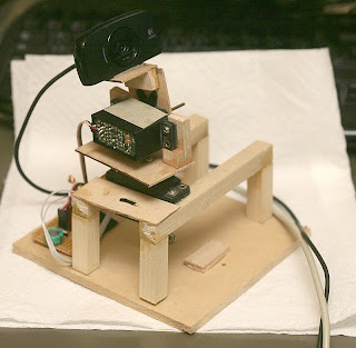
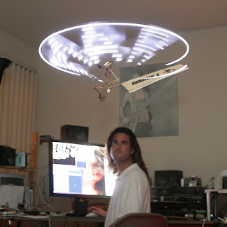
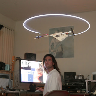
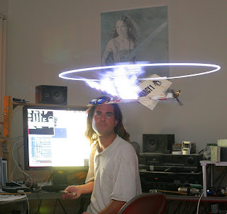
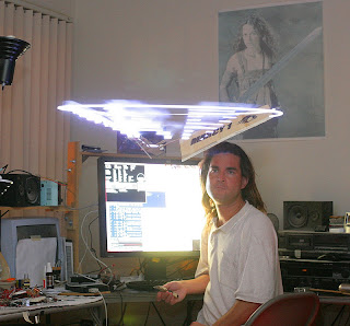
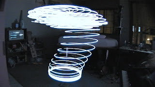
The mane requirement for Marcy 1 was always the most advanced flying thing known to man, hovering autonomously, showing POV synchronized to Evans Blue: The Darkness That Follows. 2 years after envisioning it, we finally got it working. It doesn't come out as well with the slow RPM as hoped.
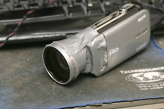
Getting the full POV image requires lying directly under it with a video camera, relying on the autopilot to work. Lying directly under it causes turbulence which makes it very unstable. A wide angle camera lens made it slightly easier to capture.
For all its complexity, uploading the images in realtime & caching in RAM wasn't fast enough. All 58 images ended up being stored in flash, with the ground station sending indexes to show. There remains an option of realtime upload for testing.
You wouldn't believe how many problems kept cropping up with the choreographed POV.
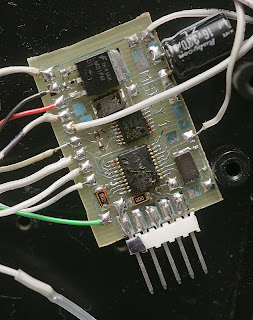
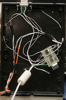
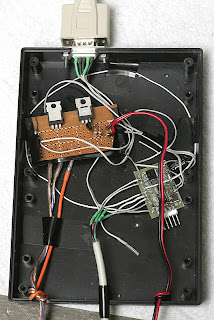
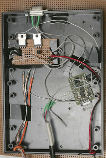
The journey began with a new ground station, condensing camera control & radio in 1 CPU & getting rid of sonar.
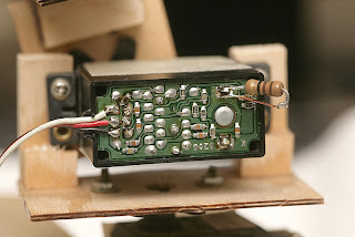
Then came getting rid of the camera board.
More hacking on the ground station got us a battery switch, so you don't need to worry about unplugging the battery.
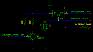
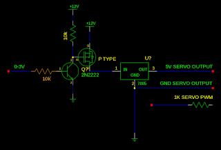
The easiest way to do it was some diabolical BJT hacking. When USB is unplugged or the autopilot is off, the BJT pulls down the MOSFET gate to 0. When the BJT base is connected to GND, it lets the MOSFET gate float to 12V. The MOSFET connects the ground to the servos & voltage regulator. The PIC couldn't get high enough to do it without the BJT.
BJT's have become the duct tape of electronics. We went with GND switching because when Vdd is disconnected, the servos suck from the PWM. Of course, when GND is floating, the servos sink current into the PWM. You can't win without some more diabolical isolation of the PWM.
We ended up putting 1k resistors on the PWM. It leaks 20mA of current, but not as much as running the servo microcontrollers.
That still didn't work.
The mane thing missing is the RC transmitter. It finally got replaced by keyboard input.
A few more bugs & the music choreography started. You wouldn't believe how far away you were from doing what you thought would take a few days in 2010. The RAM caching scheme initially proved not to be as hideously complex as feared.
Early flights with POV animation & RAM caching.
Real important is the ability to simulate it in software, but even then, it takes lots & lots of flying to test view images. Then you become aware just how reliable the flight controller is.
The wide angle lens made this shot possible.
A video DSLR would be nice, but there are only 50 full-time jobs in the whole country: 40 of them at local Wal-Marts, the other 10 in industry with 7 of them at large corporations, and the remaining three jobs are at huge museums — and all of those 50 jobs are already taken.
Continuing from my last post and hunting down the ever ending dream for "more" Skiptrovamon took a new form. This time our team goals was to keep the good things from our first airframe and..:
-Step on Known PIDs
-Make more room for cameras and FPV gear
-increase lift and decrease wing loading
-Follow DIYDRONES hardware update
-More movement-servo accuracy
-More endurance
-Eliminate image post processing
The results:
At the current state you see this model on the below pictures, the wingspan is 2 meters and the weight is 700 gramms (24,5 ounches). Front fuselage is built up by styrofoam sheets , "boom" is built with balsa using some styrofoam frames, tail system is also styro sheets with small reinforcements and the wing is made out of white 25 Kg/cub.m. EPS foam reinforced of course as needed. The wing is also folding in the middle for easy transporation...
like Skiptrovamon I, our next model is sheeted with 1mm carbon fiber:
Pros:
-As you can see is much like a 2 meter skywalker, so ready made PIDs both for APM1 and APM2 work great.
-with 4s 2600mah we achieved 40 minutes flight time.
-All up weight is 2,1 kg, incl. Cameras, APM, and FPV gear witch means it has less than 40gr/sdm wing loading!!
-Super steady even with 12,5m/s wind gusts
- 17km/h Stall speed!
- New digital high tourqe servos, consume less Amps (1,2a) and give super precise movement
- APM will keep us up to date for a time
- Mission Planner wms and georeference tool, provides us a 20cm accurasy for calculations and stiching methods.Also i can export our results to both world or local Datum. 10000 thanks Michael.
- For first time we can use geniuses like Penman for Spatial focal or even global computations instead of local.
Cons:
-Even if its steady, and noise free, camera is triggered with a 9gr servo and without stabilization we have two issues:
A. Computer rutines must compute Omega Phi Kappa, witch means we need a powerfull ground station and expensive software like Erdas
B. everything described to this wonderfull post and all the comments on wiki
-Manually i can bind image acquisition with log files but as i mentioned before, a text file with pitch, roll, yaw, baro and Nmea from the click moment could make orthorectification completely auto. maybe a guide to transform log files to excel sheets could help
- Please someone clarify on the wiki if we can use our old GPS with APM2, beacause everything is inside fuselage now
Thank everyone working to this community for making dreams happen
James
I attach a setup senario for APM2 and iam waiting any comments if you spot some errors or suggetions to improve it. electrosetup.pdf
Here's NASA's presentation at the recent AMA expo. It's about 75 minutes in five parts.
Are you a pilot looking for a handy means to help keep you out of trouble -- such as, say, flying into immoveable objects like mountains or the ground? Well, in the future, there may be an app for that!
Here a video of the test of a Nimbus 4 meters wingspan electro-glider piloted by the firmware ArduPlane 2.28xp1 (updated version with a JLN mod). Test done in HIL mode with the AeroSIM-RC v3.83 simulator connected through the AP Mission planner v1.1.30 on an ArduPilot Mega board v1.
Test Mission profile:
- Full AUTO TakeOff,
- Exec of the flight plan (8 Waypoints),
- Full AUTO Landing.
The original ArduPlane v2.28 firmware has been updated (xp1) with some improvements:
- Tuning of the final slope for a smooth touchdown, tested with the Nimbus 4 on AeroSIM-RC 3.83 in HIL mode,
- Auto calculation of the wp_radius Vs the ground_speed and the max turn angle in AUTO mode so as to get the best turning point at the Wp,
- add the CLOSED_LOOP_NAV ENABLED switch to allow redoing the flight plan after the end of the exec,
- add HIL mode test in GCS_Mavlink.pde for AeroSIM RC v3.83 (and also Xplane v9), the APMHill plugin tested with the Nimbus 4m electro-glider model,
- the CLI switch can be disabled, this allows to use only a APM CPU board without a full IMU shield for HIL test.
This is a part of the project Thermopilot (a Thermal Hunter drone): The purpose is to build a full autonomous Thermal Hunter Glider which is able to fly for a long duration in an area defined by a radius, a ceiling and a minimal altitude. The glider uses thermal soaring and dynamic soaring methods commonly used by full scale gliders during cross country soaring competitions. The ThermoPilot has been tested successfuly in flight during the summer and spring 2011 on a Cularis and a ASW24 3.50m electro-glider (below). Lot of flights have been done in high mountains (slope/ridge soaring) and above the fields (thermal soaring).
The Thermopilot project will continue intensively during the spring 2012... Stay tuned...
Regards, Jean-Louis
More infos at: http://diydrones.com/profile/JeanLouisNaudin
Hello,
This is my first blog(and I mean first ever anywhere) so please excuse the lack of the "bloginess" quality :)
I've been in testing mode with APM1 since the release of Arducopter 1 code. After a couple lost and crashed quads, I decided that my strategy for testing arducopter from now on is to start with a cheap frame/motor/prop combo, basically to iron out any bugs that maybe in newly released code or any potential errors with wiring and installation before installing it on some of my more expensive frame/motor combos. My first application of this method started with the 2.2 code and I've gotten pretty good with tuning the basic stability PIDs, essentially because I had nothing much to worry about and I was able to experiment with more aggressive PID variations to get a feel of what's going on. By the release of 2.3 code, I became mostly focused on loiter/nav/RTL tuning.
Today is my 3rd day of testing, and after running into some bad weather(sand storms and high winds), I was finally able to get some definitive patterns while varying the NAV_P and NAV_I parameters to improve the copters ability to loiter, especially that there was very little wind. I had of course tuned the copter indoors for stability and control and wanted to see what I can get in terms of navigation without changing the control feel of the copter.
For today's tests and the video below, I've followed a few basic scenarios starting from the default 2.3 navigation PIDs and only modified the NAV_P and NAV_I settings. Unfortunately and for some unknown reasons, my logs were all bad and I'm not able to show the KML files for each one of these scenarios, but I hope you get the idea from the videos.
The frame used for these tests is a Scarab Euro (from multiwiicopter.com) with KDA 1050Kv and 8X4 props.
This week I constructed, installed and tested an APM on my Nova. Everything went great! Stabilization worked like a charm and RTL worked flawlessly! Can't wait for the next few months as I explore this "new" technology. (well, new to me!)
Thank you DIYDrones for the AWESOME equipment and software... very, very cool.
-Trent
I was on NPR's Science Friday yesterday talking about drones, along with "Wired for War" author Peter Singer and MIT unmanned systems professor Missy Cummings. You can hear it here. And welcome all the listeners who are new members here!
Hi again all, Two blog posts in two days... i'm on a roll. I just finished the next set of revisions to my autotuning code. I have shifted from tuning the stab gains to tuning the rate gains. This is more dangerous but also more rewarding.
Here are the major changes:
1. Stab gains no longer tuned, switched to rate gains.
2. Addressed the issue of inconsistent user induced disturbances. Previously if the user disturbance was not consistent, the calculated performance value would be inaccurate. Now it is a scaled based on the initial pitch/roll of the copter.
3. Lowered the initial amount of gain change to 25% to mitigate the risk of in flight gain changes.
4. Added a safeguard against a gain that is too low and never returns the copter to level.
5. Moved all autotuning related logic into its own .pde file so it is easy to find
Instructions:
1. Upload the modified code (see attached zip based on v2.3)
2. Set your stab p gain to 1, stab i and d to zero
3. Set your rate p gain to some ballpark number, rate i and d to zero
4. Start your simulator
5. Bring the copter to a hover
6. Flip the ch 7 switch to the high position
7. Introduce a pitch or roll disturbance. This should be a quick movement and then return the stick to center (see video) (repeat 10 times at least).
8. Flip the ch 7 switch to the low position
9. Go to the planner and refresh the param list.
10. Set stab p = 1 + the value from rate p (maybe a little lower), stab i = 0 and stab d = .002
11. Set rate d = rate i - .003
12. Write the new values and observe in the simulator.
That should get you very close to rock solid. I have found the need to play with the stab p gain a little bit, but other than that I have had good results. Steps 10 - 12 are a bit hazy at the moment and will require some additional manual tuning. Those last steps are based on observations that I have made, not specific processes that I can guarantee will work for everyone. I am hoping some others can chime in here with some insight. Perhaps some devs can get eyes on this as well. I did try to push this into my git branch, but I am having some authentication issues at the moment.
Please watch the video for more information.... It is still uploading as of now, so if you can't see it yet just give it another 20 min or so. My videos are in 1080p so you can read my screen.
Thanks,
Adam
ArduinoCommander is a sweet new Android app for controlling Arduino with a Bluetooth shield.
From Android Market:
"Control your Arduino board from your Android device via Bluetooth using WYSIWYG interface.
Features:
- discover and connect to Arduino board with Bluetooth shield (like Sparkfun bluetooth modems: http://www.sparkfun.com/search/results?term=bluetooth+modem&what=products)
- display board firmware version, name and Firmata protocol version
- set pin mode (analog/digital input/output, pwm)
- get/set pin values
- read messages from the board (Firmata String Sysex message)
- beautiful WYSIWYG interface with 320x480, 480x800, 480x854, 1024x600 and 1280x800(?) screens support"
Good Morning DIYDrones,
I am pleased to introduce a drone platform that I have been working on for some time. I have not finalized my marketing materials, but I thought this community would like to see an early peek. Please see the included rough-edit promo video as well as my website. Questions/Comments are encouraged.
Thanks,
Adam (Sentient Drone, LLC)
"AN ADAPTABLE, LOW COST TEST-BED FOR UNMANNED VEHICLESYSTEMS RESEARCH" is the title of James Goppert's Purdue Masters Dissertation that led to the ArduPilotOne multi-vehicle version of the APM code.
Love the preface:
If anyone has ever given you a closed source autopilot and asked you to add a
feature, you know the benefit of open source software and hardware. With the new
spirit of collaboration in the software and academic communities, I can only assume
our future is bright.
Abstract:
An unmanned vehicle systems test-bed has been developed. The test-bed has been
designed to accommodate hardware changes and various vehicle types and algorithms.
The creation of this test-bed allows research teams to focus on algorithm development
and employ a common well-tested experimental framework. The ArduPilotOne au-
topilot was developed to provide the necessary level of abstraction for multiple vehicle
types. The autopilot was also designed to be highly integrated with the Mavlink pro-
tocol for Micro Air Vehicle (MAV) communication. Mavlink is the native protocol for
QGroundControl, a MAV ground control program. Features were added to QGround-
Control to accommodate outdoor usage. Next, the Mavsim toolbox was developed for
Scicoslab to allow hardware-in-the-loop testing, control design and analysis, and esti-
mation algorithm testing and verification. In order to obtain linear models of aircraft
dynamics, the JSBSim flight dynamics engine was extended to use a probabilistic
Nelder-Mead simplex method. The JSBSim aircraft dynamics were compared with
wind-tunnel data collected. Finally, a structured methodology for successive loop
closure control design is proposed. This methodology is demonstrated along with the
rest of the test-bed tools on a quadrotor, a fixed wing RC plane, and a ground vehicle.
Test results for the ground vehicle are presented.
We have been getting word individuals are having a hard time finding where to purchase AttoPilot products. AttoPilot sells through an exclusive distributor who is AttoPilot International, LLC through Chris McNair and his team. If you are looking for aircraft and AP's you may contact us at order@attopilotinternational.com or Sales@attopilotinternational.com
Kind Regards,
Chris McNair
They finally managed to produce a small manual to compile the source and program the board Multipilot32 F1 (V1 and V3) and F4 with vrobotix-ide-pro (Eclipse based).
The manual describes how to configure the environment, how to compile the sources and how to program the board. To program the board I took into consideration the following tools:
- Multipilot32F1 (V1 and V3): DFU and ST-LINK/V2
- Multipilot32F4: DfuSe and ST-LINK/V2

