Nick Goodey's Posts (17)

Sort by

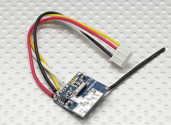
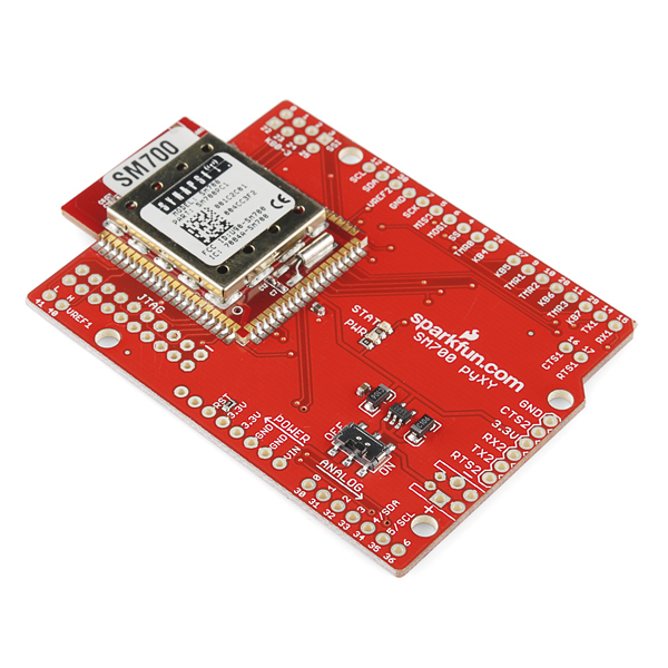
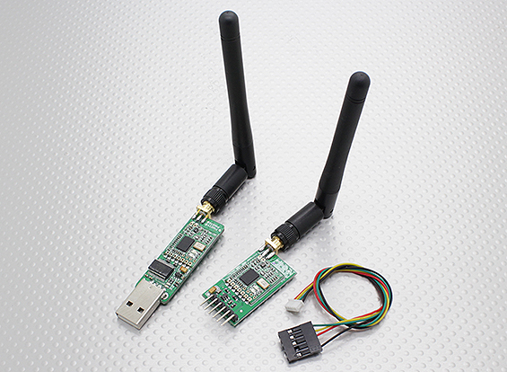
Better than an Xbee and cheaper Hobby King 433Mhz Radio Telemetry Kit 100mW

Ran this wee puppy at 57,600 full duplex no issues at 1/4 mile with the RX inside my neighbors brick post box. Seems to penetrate the masonry better than a 2.4Ghz Xbee and its half to a quarter of the price the price especially if you buy from Sparkfun. 

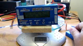
Like the Xbee it resumes comms very quickly after a power cycle which is pretty essential for RC usage. 

Arduino Xbee Receiver Arduino Nano V3.0 Microcontroller Board from hobby king

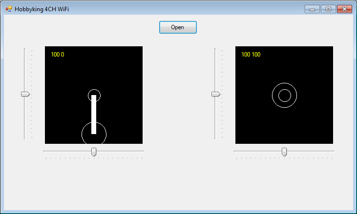
 http://kiwitricopter.blogspot.co.nz/2013/10/rx-tx-csharp-to-arduino.html
Features:
• Very small size
• Light weight (under 4 grams without antenna)
• Receiver sensitivity to -121 dBm
• Transmit power up to 20dBm (100mW)
• Transparent serial link
• Air data rates up to 250kbps
• Range of approx 1 mile
• MAVLink protocol framing and status reporting
• Frequency hopping spread spectrum (FHSS)
• Adaptive time division multiplexing (TDM)
• Support for LBT and AFA
• Configurable duty cycle
• Built in error correcting code (can correct up to 25% data bit errors)
• Demonstrated range of several kilometers with a small omni antenna
• Can be used with a bi-directional amplifier for even more range
• Open source firmware
• AT commands for radio configuration
• RT commands for remote radio configuration
• Adaptive flow control when used with APM
• Based on the HopeRF HM-TRP radio module, featuring an SiLabs Si1000 RF microcontroller

A quick test at 57,600 Baud seems like a great product and well priced at US$29.99

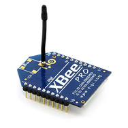
XBee Pro 60mW Wire Antenna - Series 1 (802.15.4) 

US$37.95 AND YOU NEED 2

xbee.jpg
FPV 433Mhz Radio Telemetry Kit 100mW
US$29.99 AND YOU GET A PAIR


433Mhz+Radio+Telemetry+Kit+100mW.jpg

An interesting price point comparison between Sparkfun and HobbyKing on another useful and in this case identical product. HK are almost 80% cheaper
HKlogo.png


Arduino 9DOF ArduIMU Controller ATmega328 (ACCEL/MAG/GYRO)

 US$29.99


9doHK.jpg

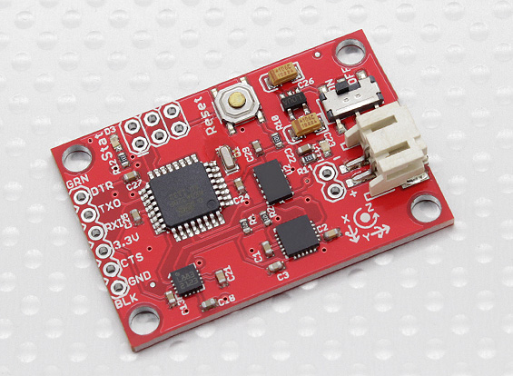
Same product from Sparkfun 9 Degrees of Freedom - Razor IMU 

US$124.95

9DOF.jpg

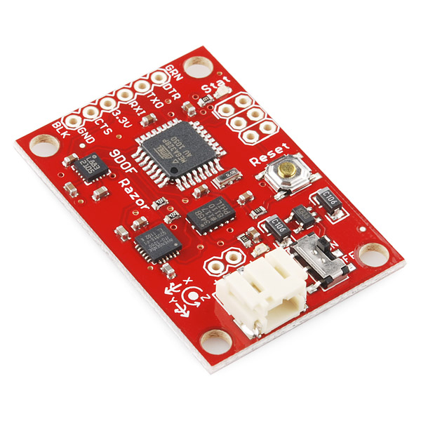
So HK sell this identical device for almost 80% less

But it get worse if are a Kiwi you buy from our local Sparkfun resellermindkits.png9 Degrees of Freedom - Razor IMU - AHRS compatible NZ$180.499DOF+Mind+Kits.jpg
 
To be fair on Mind Kits they do buy from Sparkfun but that said the bloke at Mind Kits has a way worse supply deal then Hobby King 
Read more…


Hobbyking+4CH+WiFi+Receiver.png

C# TX and Arduino RX for Coroplast Catamaran which will be self guiding with 2 GPS's one in the boat and one in the remote forming a virtual tether so the model can follow a full scale boat and still allow the operator to take control

900mm Black cat in Coroplast 6 hours to build hull 1.2Kgs Outboard 380 Watts 3300kv from 70mm EDF

900mm Black cat in Coroplast 6 hours to build hull 1.2Kgs Outboard 380 Watts 3300kv from 70mm EDF 
 
black_cat+009.JPG?width=600
 
Started off with this device after a long hiatus from the project due to other projects
 
21430.jpg?width=400
and it made me thing of a simple system, only took 4 hours to code the UI and an hour for the Arduino programming
 
I'm using this device for the comms
 
433Mhz+Radio+Telemetry+Kit+100mW.jpg?width=400
 
 
The above are available from Hobby King for $29
This is my GPS Code it decodes the following NMEA83  messages

GSA, RMC, GAA 


Its built for the Netduino Plus but will work with other Neduinos and the Fez Panda II.

It users Async comms shown below, and rises an event for each packet.


        void com_DataReceived(object Sender, SerialDataReceivedEventArgs e)
        {
            NMEAdata data = ExtractPackets(com);
            
            if (data.UTCfixTaken != null)
                OnGPSmessage(data);
            
        }

My GPS is a few years old and came from http://www.parallax.com/ in 2008 it has 2 modes one for the Parallax BS2 and a jumper selected mode where is sends NMEA packets continuously. 

Please feel free to download the code here 
Here is the Arduino RX code

#include <Servo.h>

String inputString = ""; // a string to hold incoming data
boolean stringComplete = false; // whether the string is complete
int com_state = 0;
int PackCount = 0;
char Packet[11] = {0, };

long Cooling = 0;
long PumpSpeed = 0;

Servo Servo1;
Servo Servo2;
Servo Servo3;
Servo Servo4;

#define MAX_CHAN 8
int AnIn[MAX_CHAN] = {0, };

unsigned long PPMtout = 20000;

char buf[300] = {0, };

long mS = 0;

void setup() {

pinMode(13, OUTPUT);

Serial.begin(115200);

// reserve 200 bytes for the inputString:
inputString.reserve(200);

Servo1.attach(8);
Servo2.attach(9);
Servo3.attach(10);
Servo4.attach(11);

}

void loop() {

AnIn[0] = analogRead(A0);
AnIn[1] = analogRead(A1);
AnIn[2] = analogRead(A2);
AnIn[3] = analogRead(A3);
AnIn[4] = analogRead(A4);
AnIn[5] = analogRead(A5);
AnIn[6] = analogRead(A6);
AnIn[7] = analogRead(A7);

/* RAZU-2 Six turn
This device has a gain of 55mV per amp giving a 36 Amp working range,
and a resolution of 11.3777 mA per bit with the maximum output at 5 volts
which is 1024 bits in the Arduino. By the way I should point out that
these devices on a 5 volt rail will sit around 2.5 volts with no current
flowing, so at a 2 Volt delta the out put should be around 4.5 V
*/

mS = micros();

//Calc amps
long Amps = (long)map((AnIn[1] - 512), 0, 512, 0, 36);

//Calculate cooling temp RTC on AnIn[0]
int cerr = ((int)600 - (int)AnIn[0]);

//Integrate temparature
Cooling += cerr;

if(Cooling < 1000) Cooling = 1000;
else if(Cooling > 2000) Cooling = 2000;

//Use the temperature integrator plus the motor current
//36 Amps gives us 360 bits
PumpSpeed = (long)Cooling + (Amps * 10);

//Update the outputs

Servo1.writeMicroseconds((int)PumpSpeed);

long Cyc_mS = (micros() - mS);

// print the string when a newline arrives:
if (stringComplete) {

//Servo2.writeMicroseconds((int)Packet[4]);
Servo2.write((int)Packet[5]);

sprintf(buf, "AnIn[0]:%d,AnIn[1]:%d,CoolingError:%d,Cooling:%d,MotorAmps:%d,Cyc_mS:%d", AnIn[0], AnIn[1], cerr, (int)Cooling, (int)Amps, (int)Cyc_mS );

Serial.println(buf);

stringComplete = false;
}

//ALLOW SERVOS TO UPDATE
delayMicroseconds(20000);

Cyc_mS = (micros() - mS);

}

/*
SerialEvent occurs whenever a new data comes in the
hardware serial RX. This routine is run between each
time loop() runs, so using delay inside loop can delay
response. Multiple bytes of data may be available.
*/
void serialEvent() {

while (Serial.available()) {

// get the new byte:
byte inChar = (byte)Serial.read();

switch(com_state)
{
case 0:

digitalWrite(13, HIGH);

if(inChar == 85){
Packet[0] = inChar;
PackCount = 1;
com_state = 1;
}
break;

case 1:

if(PackCount < 11)
Packet[PackCount++] = inChar;
else
{
PackCount = 0;

int sum = 0;
for (int i = 0; i < 9; i++)
sum += (int)Packet[i];

byte Chk = (byte)(sum % 256);

//sprintf(buf, "LC=%d\nRC=%d", (int)Chk, (int)Packet[10] );

//Serial.println(buf);

if(Chk == Packet[10])
{
digitalWrite(13, LOW);
stringComplete = true;
com_state = 0;

}
}
break;
}

}
}

Read more…

Small FPV Setup 2.4Ghz

200 mW TX on a 120mAh Lipo runs about 30 mins. Total weight with Lipoly 6.2 Grams, only 3.6 Grams with a 5V regulator so it runs of the main battery. The image is not great on a single Lipo cell. I will try it connected to a spare port on the RX see what the signal is like.

2.4Ghz+4+Channel+AV+Transmitter+200mW+FPV.jpg

Generate video and OSD with Arduino

This setup could be used with Arduino and this Video overlay shield

3689505327?profile=original

And this very small light Arduino its possible  to create a OSD and FPV system under 10 grams

Femtoduino, Smallest Arduino compatible board 

3689505466?profile=original

Could reduce the size and weight of my MK1 Arduino / Xbee remote significantly

Simple Arduino Xbee Remote Control TX RX

With this camera you need to block out the light from the back of this camera of the PCB tracks show in the video feed. It needs a light enclosure for the whole assembly, nice and thin so it won't drag too much on top of a wing of where ever.The wires on the camera are a little fragile so I potted them in hot glue so they don't fatigue.


3689505508?profile=original
This 2.4Ghz 200mW AV transmitter is perfect for FPV applications. This unit offers a great low cost AV solution for your micro FPV models.
Input Voltage: DC 3.7-5V 
Consumption current: 220mA 
Working Frequency: 2.4G 
Channel: 4CHS 
Output Power: 200mW 
Video input / video modulation: 1 Vp-p(FM) 
Audio input / audio modulation: 1 Vp-p(FM) 
Audio carrier: 6.0M 
Weight: 2.7g 
Dimension: 17.8*18.2*4.5mm 
Color: Silver
Transmission distance (Open Space): 50M~150M 
Operating Temperature: -10deg C ~ +55deg C
Channels: 2414, 2432, 2450, 2468


3689505528?profile=original
 
This 420TVL Micro Camera with LED is perfect for FPV applications. The included LED ring provides visibility in dark conditions. This unit is a great low cost option for your FPV model.
Specs:
Pixel: 400000 
Resolution: 420 lines
Illumination: 0.1 LUX
Lens: 2.78mm
Angle: 62 degrees
Power: 3.5~5V DC
Voltage: 100mA
Connection: 
Red = positive
Black = negative
Yellow = video
White = LED 
Weight: 2g


2.4Ghz AV FPV Receiver (Arduino Compatible)
 
This module is a 2.4Ghz band micro-power radio communications receiver, generally used to transfer audio and / or video in Arduino applications.
Designed around a low-power integrated VCO, PLL and a broadband FM video demodulator using a FM sound carrier frequency. This module complies with CE - FCC leakage requirements.
 
 3689505379?profile=original
The applications for this module are vast and only limited by your imagination. This unit can also be used as a great low cost 2.4ghz Micro FPV solution.


Features:


2.4Ghz wideband FM A/V receiver


Small footprint


Specs:


Low power consumption: 110mA


Operating voltage: 3.7-5v
Receiver Sensitivity: -90dBm
Channels: 2414, 2432, 2450, 2468
Dimensions: 36 x 23.5 x 6mm

Read more…

Generate video and OSD with Arduino

3689505327?profile=original

Interesting product if you like me are experimenting with OSD and Arduino FPV GPS Telemeterry
 
The Video Experimenter shield is an Arduino shield that lets you do all kinds of experiments with video.

  • Overlay text and graphics onto a video signal from a camera, DVR, DVD player, VCR or any other source of composite video.
  • Capture low-res video image frames for display or video processing. Give your Arduino the gift of sight!
  • Perform object detection for computer vision projects.
  • Decode NTSC closed captioning or XDS (extended data services) data embedded in television broadcasts.
  • Works with NTSC (North America, parts of South America and Asia) or PAL (most of the rest of the world) television standards. For more info on what TV standards see the map here and this list of countries and their standards
  • Uses digital pins 2, 6, 7, 8, and optionally 9. Uses analog pin 2
  • Designed for Arduino Uno, Duemilanove and equivalents. Does not work on Leonardo or Mega (more info here).

All of these capabilities are demonstrated on the projects page.


How does it work?
The Video Experimenter uses an LM1881 video sync separator to detect the timing of the vertical and horizontal sync in a composite video signal. An enhanced version of the TVout library (available below) uses this sync timing information to overlay content onto the video signal. The ATmega328 microcontroller on the Arduino includes an analog comparator that can be used to detect the brightness of the video signal at any given point in time. Using this brightness information, low-res monochrome image capture into the TVout frame buffer is possible. The ability to capture image information in memory lets you implement simple computer vision experiments.
It's important to note that this shield will not work on the Arduino Mega. Read this for more information (it's not my fault!). The Video Experimenter will work on the Seeeduino Mega with some jumper wires. Read this for more information.


Read more…

Kalman Filter Code for Yellow Plane 2

Kalman Filter Code for Yellow Plane 2 Special thanks to Kristian Lauszus, TKJ Electronics 

IMG_2221.JPG

This is the code in the main loop UpdateServos()

<code>

unsigned long msDelta = LastMicros - micros();
LastMicros = micros();

//Measure time since last cycle
double dt = (double)msDelta / 1000000.0;


// The angle should be in degrees and the rate should be in degrees per second and the delta time in seconds
double X_Angle = (double)AnIn[0];
double X_Rate = (double)AnIn[4];
double Kalman_X = kalman[0].getAngle(X_Angle, X_Rate, dt);

double Y_Angle = (double)AnIn[1];
double Y_Rate = (double)AnIn[5];
double Kalman_Y = kalman[1].getAngle(Y_Angle, Y_Rate, dt);

double Z_Angle = (double)AnIn[2];
double Z_Rate = (double)AnIn[6];
double Kalman_Z = kalman[2].getAngle(Z_Angle, Z_Rate, dt);

</code>

kalman.h can be downloaded here

<code>

/* Copyright (C) 2012 Kristian Lauszus, TKJ Electronics. All rights reserved.

This software may be distributed and modified under the terms of the GNU
General Public License version 2 (GPL2) as published by the Free Software
Foundation and appearing in the file GPL2.TXT included in the packaging of
this file. Please note that GPL2 Section 2[b] requires that all works based
on this software must also be made publicly available under the terms of
the GPL2 ("Copyleft").

Contact information
-------------------

Kristian Lauszus, TKJ Electronics
Web : http://www.tkjelectronics.com
e-mail : kristianl@tkjelectronics.com
*/

#ifndef _Kalman_h
#define _Kalman_h

class Kalman {
public:
Kalman() {
/* We will set the varibles like so, these can also be tuned by the user */
Q_angle = 0.001;
Q_bias = 0.003;
R_measure = 0.03;

bias = 0; // Reset bias
P[0][0] = 0; // Since we assume tha the bias is 0 and we know the starting angle (use setAngle), the error covariance matrix is set like so - see: http://en.wikipedia.org/wiki/Kalman_filter#Example_application.2C_technical
P[0][1] = 0;
P[1][0] = 0;
P[1][1] = 0;
};
// The angle should be in degrees and the rate should be in degrees per second and the delta time in seconds
double getAngle(double newAngle, double newRate, double dt) {
// KasBot V2 - Kalman filter module - http://www.x-firm.com/?page_id=145
// Modified by Kristian Lauszus
// See my blog post for more information: http://blog.tkjelectronics.dk/2012/09/a-practical-approach-to-kalman-filter-and-how-to-implement-it

// Discrete Kalman filter time update equations - Time Update ("Predict")
// Update xhat - Project the state ahead
/* Step 1 */
rate = newRate - bias;
angle += dt * rate;

// Update estimation error covariance - Project the error covariance ahead
/* Step 2 */
P[0][0] += dt * (dt*P[1][1] - P[0][1] - P[1][0] + Q_angle);
P[0][1] -= dt * P[1][1];
P[1][0] -= dt * P[1][1];
P[1][1] += Q_bias * dt;

// Discrete Kalman filter measurement update equations - Measurement Update ("Correct")
// Calculate Kalman gain - Compute the Kalman gain
/* Step 4 */
S = P[0][0] + R_measure;
/* Step 5 */
K[0] = P[0][0] / S;
K[1] = P[1][0] / S;

// Calculate angle and bias - Update estimate with measurement zk (newAngle)
/* Step 3 */
y = newAngle - angle;
/* Step 6 */
angle += K[0] * y;
bias += K[1] * y;

// Calculate estimation error covariance - Update the error covariance
/* Step 7 */
P[0][0] -= K[0] * P[0][0];
P[0][1] -= K[0] * P[0][1];
P[1][0] -= K[1] * P[0][0];
P[1][1] -= K[1] * P[0][1];

return angle;
};
void setAngle(double newAngle) { angle = newAngle; }; // Used to set angle, this should be set as the starting angle
double getRate() { return rate; }; // Return the unbiased rate

/* These are used to tune the Kalman filter */
void setQangle(double newQ_angle) { Q_angle = newQ_angle; };
void setQbias(double newQ_bias) { Q_bias = newQ_bias; };
void setRmeasure(double newR_measure) { R_measure = newR_measure; };

private:
/* variables */
double Q_angle; // Process noise variance for the accelerometer
double Q_bias; // Process noise variance for the gyro bias
double R_measure; // Measurement noise variance - this is actually the variance of the measurement noise

double angle; // The angle calculated by the Kalman filter - part of the 2x1 state matrix
double bias; // The gyro bias calculated by the Kalman filter - part of the 2x1 state matrix
double rate; // Unbiased rate calculated from the rate and the calculated bias - you have to call getAngle to update the rate

double P[2][2]; // Error covariance matrix - This is a 2x2 matrix
double K[2]; // Kalman gain - This is a 2x1 matrix
double y; // Angle difference - 1x1 matrix
double S; // Estimate error - 1x1 matrix
};

#endif

</code>

The Arduino code originally written by Kristian Lauszus, TKJ Electronics can be
downloaded here

I have a test harness written in C# there is a C# version of the Kalman Filter class which could very easyly be addapted for use with Fex Panda or Netduino Tiny CLR projects

The C# code for the test harness shown below can be downloaded here 

kalman+test.png?width=640

The above could be modified to accept input from a IMU or Accelerometers and Gyros

3689495868?profile=original

3689495969?profile=original

Read more…

Lighter Yellow FPV Plane 869 Grams Air Frame

3689489661?profile=original

Yellow Plane 2 with inverted V tail software modified and tested stability gyros

Missing battery and camera box have a design which should weigh 140 grams empty.

The assembly shown below weighs 684 Grams no motor or electronics.

Electronics shown weigh 110 grams ESC Arduino board, Xbee, antenna & Gyro board

Motor & prop another 120 Grams


Yellow Plane 2 with inverted V tail Video 

RX Arduino code with mixing and closed loop stability
void UpdateServos()
{

//Digital inputs TX code helper
//TxVal[8] |= (digitalRead(5) << 0);//joy 2 push
//TxVal[8] |= (digitalRead(6) << 1);//pb
//TxVal[8] |= (digitalRead(7) << 2);//slide
//TxVal[8] |= (digitalRead(8) << 3);//toggle

//Throttle TxVal[1]
//Rotary pot TxVal[2]
//Joy 1 X TxVal[3]
//Joy 1 Y TxVal[4]
//Joy 2 X TxVal[5]
//Joy 2 Y TxVal[6]
//rssi TxVal[7]
//digital TxVal[8]
//micros() TxVal[9]

//Use the pot as the gain for all channels for now
float GainPot = (float)(TxVal[2]) * 0.001f;

//Get the target values from the TX
int PitchTarg = (TxVal[3] / 10);
int RollTarg = (TxVal[4] / 10);
int YawTarg = (TxVal[6] / 10);


//Prime the Target WOZ values
if(PitchTargWOZ == 9999)
PitchTargWOZ = PitchTarg;

if(RollTargWOZ == 9999)
RollTargWOZ = RollTarg;

if(YawTargWOZ == 9999)
YawTargWOZ = YawTarg;


//Get the Centered target values
float PitchTargCentred = (float)(PitchTarg - PitchTargWOZ);
float RollTargCentred = (float)(RollTarg - RollTargWOZ);
float YawTargCentred = (float)(YawTarg - YawTargWOZ);

//Calculate gains
float PitchGain = GainPot * 1.0f;
float RollGain = GainPot * 1.0f;
float YawGain = GainPot * 1.0f;

//Get Gyro values
float PitchGyro = (float)(AnIn[2] - AnInWOZ[2]);
float RollGyro = (float)(AnIn[1] - AnInWOZ[1]);
float YawGyro = (float)(AnIn[0] - AnInWOZ[0]);

//Calc P error
float PitchError = (float)PitchTargCentred + PitchGyro;
float RollError = (float)RollTargCentred + RollGyro;
float YawError = (float)YawTargCentred + YawGyro;

//Apply gains
int PitchTrim = (int)(PitchError * PitchGain);
int RollTrim = (int)(RollError * RollGain);
int YawTrim = (int)(YawError * YawGain);

//Constaring trim authority
PitchTrim = constrain(PitchTrim, -30, 30);
RollTrim = constrain(RollTrim, -30, 30);
YawTrim = constrain(YawTrim, -30, 30);

//Dump the trim value
if((TxVal[9] & 0x4) == 0)
{
PitchTrim = 0;
RollTrim = 0;
YawTrim = 0;
}


//Calc flap anglke
int Flaps = 0;

//Apply flaps
if((TxVal[9] & 0x8) == 0)
Flaps = -25;


//Throttle
val = TxVal[1] / 10;
val = map(val, 1, 179, 30, 179);
val = constrain(val, 1, 165); // scale it to use it with the servo (value between 0 and 180)
servo[0].write(val); // sets the servo position according to the scaled value


//Vee tail

//Left Elevator Joy 1 Y TxVal[4]
val = (YawTarg + YawTrim) + (PitchTargCentred + PitchTrim);
val = constrain(val, 15, 165);
val = map(val, 0, 179, 135, 45); // scale it to use it with the servo (value between 0 and 180)
servo[1].write(val); // sets the servo position according to the scaled value


//Right Elevator Joy 1 Y TxVal[4]
val = (YawTarg + YawTrim) - (PitchTargCentred + PitchTrim);
val = constrain(val, 15, 165);
val = map(val, 0, 179, 135, 45); // scale it to use it with the servo (value between 0 and 180)
servo[2].write(val); // sets the servo position according to the scaled value


//Left Flaperon
val = 90 + (RollTargCentred + Flaps) + RollTrim;
val = constrain(val, 15, 165);
val = map(val, 0, 179, 165, 15); // scale it to use it with the servo (value between 0 and 180)
servo[3].write(val); // sets the servo position according to the scaled value

//Right Flaperon
val = 90 + (RollTargCentred - Flaps) + RollTrim;
val = constrain(val, 15, 165);
val = map(val, 0, 179, 165, 15); // scale it to use it with the servo (value between 0 and 180)
servo[4].write(val); // sets the servo position according to the scaled value


//Joy 2 x nose Wheel
val = (TxVal[6] / 10);
val = map(val, 0, 179, 55, 125);
servo[5].write(val); // sets the servo position according to the scaled value

}


Read more…

IMG_2136.JPG

Revised Yellow FPV Plane with gyro stability system added, Worked best with analogue inputs from Murata piezo gyro sensors of a dead KK board filtered taking a 10 point average. Yaw compensation is currently not used as there is no rudder presently.

Gyro stability code in action

https://www.youtube.com/watch?v=IrSxP9YsLpY&hd=1

The RX board using the Arduino Nano weighs 12 grams

The code on Google Drive

Read more…

:) IT FLY'S :) Maiden flight of Yellow Plane Hextronic DT850 Turnigy 2200mAh Xbee Arduino Controller

3689487069?profile=original

YouTube

Maiden flight of Yellow Plane flown by a local pilot Richard to avoid instant crash I would cause. A little tail heavy but flew pretty well on a gusty day, I'm told control was good. Ended in a crash but not too badly damaged, learned a lot. I'm just chuffed if flew looks pretty good on such a windy, which is pretty standard for the south island this time of year.

My scratch built FPV platform. Took around 30 hours to build mostly Corriboard with some ply, aluminium and carbon fiber spars. Total material cost around 50 US$. Got a DT700 (see tests data here) which hopefully will be an adequate power source. Its a modular design based around an armature, so wings and tail etc are bolted on and can be exchanged for testing parts and ideas. Have a pair of KM3 wings and the Corriboard one shown below.

Please see the spread sheet here Yellow Plane Data 

Based around a stiff wooden armature and two aluminium tail spars the wings are removable for transportation. According to my calculations the wing loading is 15.5 Oz/Ft² at a flight weight of 1700 Grams. A glass fiber nose has been molded and is curing now which is around 80 grams, which will contain the FPV gear and the main battery.

Home brew Arduino Xbee remote control 

Read more…

3689486664?profile=original

Cobbled together 90 mm fan with 250 Watt  Turnigy L2210-1650 Bell Style Motor (250w) seeing if I can get decent efficiency from a small fan turning slower. 


On 14.8 Volts its pushing almost 500 Grams, not so bad thrust mapping is as follows.


100 Grams 1.9 A 27.6 Watts
156 Grams 3.0 A 42.9 Watts
197 Grams 3.9 A 55.1 Watts
257 Grams 5.5 A 76.0 Watts
296 Grams 6.7 A 90.9 Watts
340 Grams 7.9 A 105.5 Watts
432 Grams 10.7 A 138.1 Watts
492 Grams 12.5 A 155.7 Watts

The data in a spread sheet

The tests were run on two 7.4V 1300mAh Turnigy 20C Lipo's in series, I figure the motor will survive full throttle bursts on 4C and its 10 Amps short of the max, 100 Watts below its spec.

Its surprising as the same motor with a 8 X 6 prop pulled 23.3 Amps on a 3C yielding 520 Grams of thrust at 232.3 Watts.

3689486708?profile=original

Weighs around 150 grams.

Need a plane for it should be pretty ugly with such a big fan

 
Thust               500 Grams
EDF & Motor 150 Grams
Battery            178 Grams
 
If the air frame can be built in 172 grams it will have an thrust to mass ratio of 1:1 pretty ambitious
 
@ 1:1.75 its 230 Grams
@ 1:1.5 its 344 Grams
 

Foam and Coroplast SPAD for the EDF Jet


A mass of 500 or 750 grams give a wing loading's of 13 oz/ft² and 19 oz/ft² respectively
Wing area 1.3855 ft²
Dihedral 5º
Kf2 A symmetric trapezoidal wings and tail plane
My Xbee based controller with appropriate RX software for the Jet

3689486731?profile=original
I will probably let the top stick out above the fuselage structure as its really a pusher prop in a tube. The jet location gives a neutral balance as is with out the tail and elevator or any servos.
If I sling the battery underneath I should have plenty of options for trimming the centre of gravity, as well as keeping it low compared to the motor which is mounted higher than the above example.

The wings are braced with bamboo skewers cheap as. I will chamfer the top leading edges as that's what most people seem to do.

I am advised that the elevators will need lots of authority so I will fashion quite large ones :)

3689486568?profile=original
Not sure there is anything to gain from having any sort of thrust tube yet, will test some ideas on the scales, and do some more reading. My intuition says keep the back low as possible behind the jet only the tail fin in the air flow and brace the structure from beneath. The 5º of dihedral gives some longitudinal stiffness so another V section in Coroplast running the entire length should do the job I think.
3689486593?profile=original


Read more…

Building the Arduino Xbee Receiver

3689485705?profile=original

Building the Arduino Receiver. The whole board and micro weighs in at 22 grams. The supply will be a 3C Lipolly


The Xbee Vin (max 16V) and Arduino VIN (max 20V) hare both powered from the supply battery 11.1 V directly as the both have internal regulators.  This helps isolate any noise from the Arduino and ore servos from being superimposed on the Xbee supply rail.


The Xbee need around 220mA and the Arduino say 100 mA driving the servo PWM signals, and not the motors. All up say 750mA in a 750mAh 3C


Working on Yellow Plane

Read more…

Better Battery Box For Yellow FPV Plane

Better Battery Box For Yellow FPV Plane

3689484785?profile=original

An improved battery box for my FPV plane project.  The front wheel need mounting on a spring piece, as do the rear struts. I don't like the idea of having no suspension at all, so will probably put springy trailing arms to let the rear wheels soak up some bumps without transmitting the landing/crashing forces directly to the frame.


Will be using a 2.5 liter Coke bottle as an aero shield with some foam board  internals to support the camera OSD GPS ect

Read more…

Raztech Hall Effect Current Sensors

raztech+5+turn+b.png

Raztech Hall Effect Current Sensors


These guys gave me some samples a few years ago when I was working on a commercial project as a consultant Hall Effect Sensors 

Its a nice way to measure current as there is no shunt to reduce the voltage which is in short supply on RC models.
RAZC-2.PNG

This example is like the one I have for high range current like in yellow boat. You 20 mV change in the output signal for each amp. 


Therefore the range should be a 2 Volts delta for 100 amps going through the wire.
raztec+100+A.png
The resolution on a Arduino 10 bit converter give a current resolution of 4.8828125 mV per bits so 409 values representing the 2 volt output change for 100 amps, so approximately 250mA per bit which should be fine when measuring such a chunky supply current.

Notice the chunky wire I fitted there is no other filtering so it will be interesting to see if we need to do some work in the software to filter out any noise.

The whole thing is then potted with hot glue to protect it and a  gold connector soldered to the end of the thick cable.

Next I have a lower range version which should be good for my FPV plane.
 
RAZU-2.PNG
This device is intended to allow the user to add as many turns as needed to get the range they want, each turn doubling the gain

The one I have has 5 turns of fairly chunky 4 mm² solid copper should be good for the job.


raztech+5+turn+b.png
This device has a gain of 55mV per amp giving a 36 Amp working range, and a resolution of 88 mA per bit with the maximum output at 5 volts which is 1024 bits in the Arduino. By the way I should point out that these devices on a 5 volt rail will sit around 2.5 volts with no current flowing, so at a 2 Volt delta the out put should be around 4.5 V. I will test this and see how good it is however I don't think it matters if the top end is clipped of as you seldom operate at maximum current for very long in practice.

raztech+5+turn+c.png

Here it is all potted up with decent sized cables soldered to the ends of the solid copper turns.

I have tested both of these and they work as described measured against my HobbyKing HK-010 Wattmeter & Voltage Analyzer which is turning out to be a handy tool.  Going to need a scope next maybe next year.
hall+effect+liniarity.png
Raztec data sheet info
raztec+data.png
Read more…
IMG_1998.JPG
 
Yellow Plane now has a battery box and nose for the FPV gear, The centre of gravity is on the wing center line with these batteries, the whole pod can be relocated on the keel as required as  its only bolted on. I am trying to keep from blocking the flow to the prop with the nose pod as much as I can. It will likely need wheels or skids projecting aft of the battery pod.
 Holds 3 Turnigy 2200mAh 3C 
IMG_1999.JPG

IMG_2000.JPG
 Put a tilt mechanism on the camera
IMG_2001.JPG

The camera OSD, GPS and 5.8Ghz TX all mounted in the same module
IMG_2002.JPG

IMG_2003.JPG
 There is another 700mAh 3C to be mounted for the electronics supply
IMG_2004.JPG
Getting some smaller lighter lenses
 
The Hobby King F1.2 lense is a hulking 70 Grams +
1/3-inch Sony CCD Video Camera 700TV Lines F1.2 (PAL)
 The FPV parts are all mounted on the top cover so an alternate cover can be used if required
IMG_2005.JPG
Read more…

yellow+boat+004.png

Corriboard Yellow Boat at Charteris Bay Banks Peninsula New Zealand 


Displacement 1280 g power 350 Watts. With all the FPV gear. Have no way of recording the goggle feed presently, but the GPS read 22Kmh on the OSD not too bad 

The FPV key fob camera.  This was my first time using goggles an with the boats motion I found it caused a physical reaction in that I was reacting to the boats movement on the water. The scale size of the waves is huge after a minute or so I actually felt a little nauseous. Better to learn about this with a boat than with a plane I think.
Yellow+Boat+Watts+vs+Amps.png

FPV Bits

Hobbyking G-OSD II Mini OSD System w/GPS Module

5.8g 200mw FPV Wireless AV Tx & Rx Set

2C Turnigy 5000mAh 20C
2 X NQD 20mm Jet Drives RPM 28,000 @ 90% of 7.4V
2 X Turnigy 2627 4200kv Imax 22A Vmax 11.1
2 X Turnigy AE-30A Brushless ESC


FPV setup weighs 183 grams
IMG_1831.JPG

IMG_1832.JPG
 FPV setup dds almost 400 grams but she still has a decent pull out on to the  plane
IMG_1833.JPG
Another twin engine jet boat I found
Fd91780.jpg

Just as long as I don't look like an idiot :)
home+made+goggles+2.png
The growth on the head is based on these
2907716357534040_1.jpg
The OSD image from HobbyKing

426255707X53414X20.jpg
IMG_1832.JPG

IMG_1833.JPG

IMG_1831.JPG

IMG_1833.JPG

IMG_1831.JPG

IMG_1832.JPG

Read more…
dt850+max+thrust.png

Better trust then the 100 Amp ESC withe the Dlux 

Test setup 2200mAh 3C 20C Lipoly DT850 motor 11 X 4.7 Pusher Prop
 
DT850+D4023-850.jpg
 
 
Rpm/V: 850kv
Max Watts: 380W
Max Amps: 35A
Max Volt: 7.4~14.8v (2~4S)
Idle Current: 1.5A
Resistance: 0.039 ohms
Weight: 107.1g
Shaft: 4mm x 39mm threaded
Can Size: 41mm
Mount Diameter: 30mm
 
dlux30a-main.jpg
 
Spec.
Max Cont. Current: 30A
Max Burst Current: 40A
Max BEC Current: 2A
BEC Voltage: 5.5v 
LiPo: 2~4S
Weight: 23grams
Max RPM (2-pole): 200,000rpm
Size: 51 x 27 x 11mm
Motor Plug: Female 3.5mm bullet Connector
 
HK-010.jpg
 
Specification:
Working voltage range: 0-60V
Working current range: 0-100A
Power: 0-6000W
Cell count: 1-6S
Battery type: LiPo/LiFe/LiIon 
Weight: 140g
Dimensions: 103x49.5x20mm
Working temperature range: -20~50°C
Read more…

synapse.jpg

pyXY - Synapse SM700 Dev Board May Be better than Xbee and seems cost effective
8 X 12 bit analogue inputs could do a RC controller without Arduino's  

This Data Sheet details the SM700PC1 module, which includes:

  • Powerful 32-bit TDMI ARM7 microprocessor      
  • Large on-board memory resources
  • 2.4 GHz RF Frequency (2400 - 2483.5 MHz)      
  • -96 dBm Rx sensitivity
  • Up to 100mW output power      
  • +20dBm Tx output power
  • 16 RF Channels      
  • 2.0 to 3.6 Volts Vcc
  • Small footprint: 1” x 1.4” (25.4mm x 36.5mm)      
  • Low power consumption:
  • Operating temperature: -40°C to +85°C        
  • Transmit mode……193mA
  • Over 1.5 miles range        
  • Receive mode………30mA
  • FCC, CE and IC certified      
  • Integrated F-antenna
  • Accurate 12-bit ADC for precision sensors      
  • Small surface-mount IC footprint

Datasheet Sparkfun ($69)

  • Freescale MC13224V 32-bit ARM7 Processor
  • Integrated 2.4GHz 802.15.4 transciever
  • Up to 100mW Output Power
  • 96k RAM
  • Arduino Shield Compatible
  • 12-bit ADC, 2 UARTS, I2C and SPI
  • SNAPpy Interpreter (Python-like language)
  • Over-the-Air Programmable with Another Synapse Module!
  • Can be used as a Synapse shield for Arduino

Description: It may look like a regular ol' Arduino shield, but don't be fooled, the pyXY (pronounced 'pixie') is a full blown shield-compatible development board. The heart of the pyXY is the Synapse SM700 wireless network module, a mesh network powerhouse that packs a 32-bit ARM7 processor with plenty of on-board memory. What's more, the SM700 can be programmed in SNAPpy, a Python derivative that makes building interactive networks a snap.

 
The shield-compatible form factor and pin assignment make this the perfect platform to develop a wireless sensor device, but if you want to add it to your existing Arduino-powered application, no worries. The pyXY has jumpers to swap the TX and RX lines, effectively taking it from development board to Arduino shield.
 
Don't underestimate the processing power of the SM700, though. With 96k RAM, 46 GPIO pins including 8 12-bit ADCs, and the SNAP OS, the pyXY is a capable board all on it's own. Simply connect the board to your computer using a 3.3V FTDI Basic Breakout and download the Synapse Portal software and you're ready to write and deploy some SNAPpy script. If you have more than one module, you can even program them over-the-air! The Portal software also allows you to tether your Synapse network to full-featured Python scripts on your computer, giving your mesh access to an entire world of libraries and resources.


Read more…