All Posts (14029)

Sort by

TF-Luna can be used with PixHawk1 for the purpose of obstacle avoidance and Altitude Hold. But because it’s a short range sensor so in most cases it is used for obstacle avoidance.

  1. TF-Luna Settings:
  2. Note: If there are any spikes while using the LiDAR as obstacle avoidance sensor then it is advised to change the frame rate to 250Hz, see the command details having command ID as 0x03 in the manual and for the sake of convenience configuring other parameters (like setting frame-rate, changing address etc.) in UART mode is recommended if you don’t have IIC-USB converter. A simple UART-USB adapter or board should work.

At the time of writing this document latest firmware was 3.3.0. For firmware upgrade please contact our technical support.

The default communication of TF-Luna is UART. LiDAR comes with a single cable. In order to use IIC, the cable needs a little modification, details are mentioned in the coming paragraph. Please see TF-Luna IIC communication pin details as below:

 10995528260?profile=RESIZE_710x


If we look at the pin configuration of TF-Luna, IIC can be set by grounding pin-5 in addition to the other four pins. For this purpose a customized cable is needed because in IIC mode we need to connect both pin-4 and pin-5 to the ground.

The modified cable is shown below. I have connected green wire (pin-4) and blue wire (pin-5) to single pin which will go to the GND pin of the source. Leave pin-6 connected. Please ignore the color standard in this case as black wire represents RXD/SDA while yellow wires represents TXD/SCL, just follow the pin numbering according to the user-manual.   

 10995528097?profile=RESIZE_710x


TF-Luna, TFmini-S, TFmini-Plus and TF02-Pro can be interfaced with IIC port of PixHak1 flight controller. Their settings are almost same. We take two TF-Luna LiDARs as example and set the address 0x08 and 0x09 separately.

  1. PixHawk Connection:

 We take PixHawk1 flight controller as an example:

10995530287?profile=RESIZE_710x

Figure 1: Schematic Diagram of Connecting TF-Luna to I2C Interface of PixHawk

Note:

  1. Default cable sequence of TF-Luna and PixHawk are different, please change it accordingly (SDA and SCL wires need to be interchanged). Look at the pinout of controller, pin configurations are starting from left to right:

 10995529253?profile=RESIZE_710x

  1. IIC connector should be purchased by user
  2. If TF-Luna faces down, please take care the distance between lens and ground, it should be larger than TF-Luna’s blind zone (20cm)
  3. If more TF-Luna need to be connected (10 LiDARs are supported), the method is same.
  4. Power source should meet the product manual demands:5V±0.5V, larger than 150mA (peak current)*number of TF-Luna
  5. Parameters settings:

Common settings:

AVOID_ENABLE= 2 [if 3 = UseFence and UseProximitySensor doesn’t work in IIC then choose 2 = UseProximitySensor]

AVOID_MARGIN=4

PRX_TYPE=4

Settings for first TF-Luna:

RNGFND1_ADDR=08 [Address of #1 TF-Luna in decimal]

RNGFND1_GNDCLEAR=25 [Unit: cm, depending upon mounting height of the module and should be larger LiDAR than non-detection zone]

RNGFND1_MAX_CM=400 [It could be changed according to real demands but should be smaller than
effective measure range of LiDAR, unit is cm] 

RNGFND1_MIN_CM=30 [It could be changed according to real demands and should be larger than
LiDAR non-detection zone, unit is cm] 

RNGFND1_ORIENT=0 [#1 TF-Luna real orientation]

RNGFND1_TYPE = 25 [TF-Luna IIC same as TFmini-Plus IIC]


Settings for second TF-Luna:

RNGFND2_ADDR=09 [Address of #2 TF-Luna in decimal]

RNGFND2_GNDCLEAR=25

RNGFND2_MAX_CM=400

RNGFND2_MIN_CM=30

RNGFND2_ORIENT=25 [#2 TF-Luna real orientation]

RNGFND2_TYPE=25 [TF-Luna IIC same as TFmini-Plus IIC]

Upon setting of these parameters, click [Write Params] on the right of the software to finish the process.

If the error message “Bad LiDAR Health” or “Bad Proximity” appears, please check if the connection is correct and the power supply is normal.

How to see the target distance from the LiDAR: press Ctrl+F button in keyboard, the following window will pop out:

 10995530864?profile=RESIZE_710x


Click button Proximity, the following window will appear:

 10995530899?profile=RESIZE_710x

The number in green color means the distance from LiDAR in obstacle avoidance mode(the number only refresh when this window opens, closes, zooms in or zooms out, it doesn’t mean the real time distance from LiDAR and will not be influenced in Mission Planner The mission planner version at the time of writing this tutorial was v1.3.76.

Read more…

TF03 standard version comes with CAN interface and can be interfaced with PixHawk1 CAN port or any flight controller which has Ardupilot firmware flashed and having CAN interface. Support for CAN protocol has been added to Ardupilot firmwares, starting from Copter 4.2.0 for the purpose of obstacle avoidance and Altitude Hold.

  1. 1.  TF03-CANSettings:

It should be noted that TF03 has two different hardware versions for 485/RS232 and UART/CAN. So when  buying  LiDAR,  please  pay  attention  to  buy  LiDAR  with  CAN  interface  (standard  version). Multiple LiDARs can be interfaced to a single CAN bus. We need to assign different CAN IDs to each LiDAR just like we do for IIC communication. The baud-rate of each LiDAR needs to be set to the same value. On LiDAR side we have two types of CAN IDs:

    Send ID (Transmit CAN ID): it becomes Receive ID on CAN bus side (we need to set this ID

to a new value ifwe are connecting multiple LiDARs.)

    Receive ID: it becomes Send ID on CAN bus side

I will consider three LiDARs example but Ardupilot supports up to  10 sensors. The commands are mentioned in details in the manual of LiDAR but I will add them here for convenience. It is still advised to read the manual of LiDAR carefully there are important points.

5A 08 50 04 00 00 00 B6 [CHANGE SEND ID TO 04]

5A 08 50 05 00 00 00 B7 [CHANGE SEND ID TO 05]

5A 08 50 06 00 00 00 B8 [CHANGE SEND ID TO 06]

5A 05 45 02 A6 [CHANGE INTERFACE TO CAN]

5A 04 11 6F [SAVE SETTINGS]

5A 08 50 03 00 00 00 B5 [CHANGE RECEIVING ID BACK TO 03]

Some details about terminating resistor on LiDAR: Terminating resistor on LiDAR is connected by default, utilizing this resistor helps in reducing equivalent resistance of transmission wires, because adding more resistors in parallel will reduce the equivalent resistance. I have tested with total five LiDARs with all LiDARs having resistors enabled.

For sending the above commands, in case you dont have CAN analyzer and only have TTL-USB adapter, it is suggested that first configure the IDs and then switch the interface from UART to CAN because if you first switch interface then you cant use UART interface of LiDAR. In that case you have to use CAN analyzer to set different IDs. 

Once you are done with above settings then it’s time to move to physical connection and Ardupilot firmware settings.

We take three TF03-CAN as an example in this passage and set the addresses to 0x03 and 0x04 and 0x05 separately. The default sending ID of LiDAR is 0x03 so leave it for one LiDAR and configure for other two LiDARs to 0x04 and 0x05.

  1. 2.PixHawkConnection:

The following diagram shows how to interface TF03-CAN with PixHawk flight controller.

 10995521688?profile=RESIZE_710x


Figure 1: Schematic Diagram of Connecting TF03 to CAN Interface ofPixHawk1

Note

  1. 1.   Pleasepayattention to connect correct wire to correct pin of flight controller. Look at the pinout of controller, pin configurations are starting from left to right:

 10995522462?profile=RESIZE_400x

Figure 2: Pin details of CAN Interface ofPixHawk1

  1. 2.   Relatedconnectorsneed to be purchased by user, LiDAR connector is 7-pin JST with25mm pitch.
  2. 3.   IfLiDARfaces down, please take care the distance between lens and ground, it should be larger than LiDAR’s blind zone ( 10cm).
  3. 4.   IfmoreLiDARs need to be connected ( 10 LiDARs can be connected), the method is same.
  4.   Powersourceshould meet the product manual current and voltage requirement: 5V to 24V, larger than 150mA*number of LiDAR. I used 12V supply just for reference.
  5. 3.  Parameterssettings:

Common settings for obstacle avoidance :

AVOID_ENABLE = 3 [if 3 = UseFence and UseProximitySensor doesn’t work in IIC then choose 2 =

UseProximitySensor]

AVOID_MARGIN = 4

PRX_TYPE = 4

Settings for CAN-1 port:

CAN_P1_DRIVER = 1

CAN_D1_PROTOCOL = 11

CAN_P1_BITRATE = [Baud-rate: For TF03 the baud-rate needs to be set to 1000000.]

In case of pixhawk1 we only have one CAN interface but if there are more than one interfaces then configure the parameters for CAN-2 interface. 

Settings for CAN-2 port:

CAN_P2_DRIVER = 1

CAN_D2_PROTOCOL = 11

CAN_P2_BITRATE = [Baud-rate: For TF03 the baud-rate needs to be set to 1000000.] 

Settings for first TF03:

RNGFND1_RECV_ID = 3 [CAN Transmit ID of #1 TF03 in decimal]

RNGFND1_GNDCLEAR=15 [Unit: cm, depending upon mounting height of the module and should be larger LiDAR than non-detection zone. This parameter is required to be configured for altitude hold, it is the installation height of LiDAR from ground.]

RNGFND1_MAX_CM = 400 [It could be changed according to real demands but should be smaller than effective measure range of LiDAR, unit is cm]

RNGFND1_MIN_CM=30 [It could be changed according to real demands and should be larger than LiDAR non-detection zone, unit is cm]

RNGFND1_ORIENT=0 [#1 TF03 real orientation]

RNGFND1_TYPE = 34 [TF03 same as TF02-i and TFmini-i CAN] 

Settings for second TF03:

RNGFND2_RECV_ID = 4 [CAN Transmit ID of #2 TF03 in decimal]

RNGFND2_MAX_CM=400 

RNGFND2_MIN_CM=30

RNGFND2_ORIENT = 6 [#2 TF03 real orientation]

RNGFND2_TYPE = 34 [TF03 same as TF02-i and TFmini-i CAN] 

Settings for third TF03:

RNGFND3_RECV_ID = 5 [CAN Transmit ID of #3 TF03 in decimal]

RNGFND3_MAX_CM=400 

RNGFND3_MIN_CM=30

RNGFND3_ORIENT = 4 [#3 TF03 real orientation]

RNGFND3_TYPE = 34 [TF03 same as TF02-i and TFmini-i CAN] 

Upon setting of these parameters, click [Write Params] on the right of the software to finish.

If the error message “Bad LiDAR Health” appears, please check if the connection is correct and the power supply is normal. Please turn-off completely the flight controller after configuring the parameters, otherwise changes will not take place. If your battery is connected to your flight controller, please disconnect it as well.

How to see the target distance from the LiDAR: press Ctrl+F button in keyboard, the following window will pop out:

 10995523652?profile=RESIZE_710x

 Click button Proximity, the following window will appear:

 10995523853?profile=RESIZE_584x

The number in green color means the distance from LiDAR in obstacle avoidance mode the number refreshes when the distance changes or window opens, closes, zooms in or zooms out, and this distance will not be influenced in Mission Planner, the version used at the time writing this tutorial is v1.3.72.

Altitude Hold using CAN Interface:

Let say we use fourth LiDAR for the purpose of Altitude Hold. Connect the flight control board to mission planar, Select [Full Parameter List] in the left from the below bar-[CONFIG/TUNING]. Find and modify the following parameters:

PRX_TYPE = 0 [on equal to 4 also gives the value if RNGFND4_ORIENT = 25]

RNGFND4_RECV_ID = 6 [CAN Transmit ID of #4 TF03 in decimal]

RNGFND4_GNDCLEAR = 15 [Unit: cm, depending upon mounting height of the module and should be larger LiDAR than non-detection zone. This parameter is required for Altitude Hold.]

RNGFND4_MAX_CM = 400 [It could be changed according to real demands but should be smaller than effective measure range of LiDAR, unit is cm]

RNGFND4_MIN_CM = 30 [It could be changed according to real scenario and should be larger than LiDAR non-detection zone, unit is cm]

RNGFND4_ORIENT = 25 [#4 TF03 real orientation]

RNGFND4_TYPE = 34 [TF03 same as TF02-i and TFmini-i CAN]

Upon setting of these parameters, click [Write Params] on the right of the software to finish.

If the error message “Bad LiDAR Health” appears, please check if the connection is correct and the power supply is normal.

Select option sonarrange, see following picture:

 10995523879?profile=RESIZE_710x


The altitude distance from the LiDAR will be displayed in Sonar Range (meters), see the following

picture:

 10995523891?profile=RESIZE_180x180

Read more…

PIXY SM | The Advance Kit for Industrial Missions

We're pleased to release the kit for industrial missions with the Pixy SM. The new Pixy SM Advanced Kit can enhance the camera stability in the air, reduce the resonance vibration that gives better images and videos and serve well for inspecting structures like buildings, windmills, bridges, etc.

10996671260?profile=RESIZE_710x
The new damping also can work flawlessly for mapping missions, meaning the system can be used for inspection & mapping mode without changing others.


💬Contact us at contact@gmail.com for further discussions.
🌏PIXY SM - ADVANCED KIT FOR INDUSTRIAL MISSIONS

Read more…

Note: This document is applicable to Cube Orange and Cube Black flight controllers. The IIC interface available that can be used to connect multiple TF-Lunas is the same on both flight controllers. TF-Luna can be used with PixHawk Cube for the purpose of obstacle avoidance and Altitude Hold. But because it’s a short range sensor so in most cases it is used for obstacle avoidance.

  1. TF-Luna Settings:

Note: If there are any spikes while using the LiDAR as obstacle avoidance sensor then it is advised to change the frame rate to 250Hz, see the command details having command ID as 0x03 in the manual and for the sake of convenience configuring other parameters (like setting frame-rate, changing address etc.) in UART mode is recommended if you don’t have IIC-USB converter. A simple UART-USB adapter or board should work.

At the time of writing this document latest firmware was 3.3.0. For firmware upgrade please contact our technical support.

The default communication of TF-Luna is UART. LiDAR comes with a single cable. In order to use IIC the cable needs a little modification, details are mentioned in the coming paragraph. Please see TF-Luna IIC communication pin details as below:

10972789873?profile=RESIZE_710x


If we look at the pin configuration of TF-Luna, IIC can be set by grounding pin-5 in addition to the other four pins. For this purpose a customized cable is needed because in IIC mode we need to connect both pin-4 and pin-5 to the ground.

The modified cable is shown below. I have connected green wire (pin-4) and blue wire (pin-5) to single pin which will go to the GND pin of the source. Leave pin-6 connected. Please ignore the color standard in this case as black wire represents RXD/SDA while yellow wires represents TXD/SCL, just follow the pin numbering according to the user-manual.   

 10972790082?profile=RESIZE_710x


TF-Luna, TFmini-S, TFmini-Plus and TF02-Pro can be interfaced with IIC port of PixHak Cube Orange flight controller. Their settings are almost same. We take two TF-Luna LiDARs as example and set the addresses 0x08 and 0x09 separately.

  1. PixHawk Cube Connection:

We take PixHawk Cube Orange flight controller as an example:

 10972790471?profile=RESIZE_710x

 Figure 1: Schematic Diagram of Connecting TF-Luna to I2C Interface of PixHawk Cube

Note:

  1. Default cable sequence of TF-Luna and PixHawk Cube are different, please change it accordingly (SDA and SCL wires need to be interchanged). Look at the pinout of controller, pin configurations are:

10972790669?profile=RESIZE_710x

  1. IIC connector should be purchased by user
  2. If TF-Luna faces down, please take care the distance between lens and ground, it should be larger than TF-Luna’s blind zone (20cm)
  3. If more TF-Lunas need to be connected (10 LiDARs are supported), the method is same.
  4. Power source should meet the product manual demands:5V±0.5V, larger than 150mA (peak current)*number of TF-Luna
  5. Parameters settings:

Select [CONFIG/TUNING] and then click on [Full Parameter List] in the left from the below bar. Find and modify the following parameters.

Common settings:

AVOID_ENABLE= 2 [if 3 = UseFence and UseProximitySensor doesn’t work in IIC then choose 2 = UseProximitySensor]

AVOID_MARGIN=4

PRX_TYPE=4

Settings for first TF-Luna:

RNGFND1_ADDR=08 [Address of #1 TF-Luna in decimal]

RNGFND1_GNDCLEAR=25 [Unit: cm, depending upon mounting height of the module and should be larger LiDAR than non-detection zone]

RNGFND1_MAX_CM=400 [It could be changed according to real demands but should be smaller than
effective measure range of LiDAR, unit is cm] 

RNGFND1_MIN_CM=30 [It could be changed according to real demands and should be larger than
LiDAR non-detection zone, unit is cm] 

RNGFND1_ORIENT=0 [#1 TF-Luna real orientation]

RNGFND1_TYPE = 25 [TF-Luna IIC same as TFmini-Plus IIC]


Settings for second TF-Luna:

RNGFND2_ADDR=09 [Address of #2 TF-Luna in decimal]

RNGFND2_GNDCLEAR=25

RNGFND2_MAX_CM=400

RNGFND2_MIN_CM=30

RNGFND2_ORIENT= 6 [#2 TF-Luna real orientation]

RNGFND2_TYPE=25 [TF-Luna IIC same as TFmini-Plus IIC]

Upon setting of these parameters, click [Write Params] on the right of the software to finish the process. After writing the parameters you need to power off the controller and then turn it on to apply the setting changes. If the error message “Bad LiDAR Health” or “Bad Proximity” appears, please check if the connection is correct and power supply is normal. How to see the target distance from the LiDAR: press Ctrl+F button in keyboard, the following window will pop out:

And click button Proximity, the following window will appear:10972790863?profile=RESIZE_710x


The number in green color means the distance from LiDAR in obstacle avoidance mode(the number only refresh when this window opens, closes, zooms in or zooms out, it doesn’t mean the real time distance from LiDAR and will not be influenced in Mission Planner. The mission planner version at the time of writing this tutorial was v1.3.76.
Read more…

TF02-Pro can be used with PixHawk for the purpose of obstacle avoidance and Altitude Hold.

  1. TF02-Pro Settings:

Note: If there are fluctuations in readings then set the frame rate to 250Hz, see the details in chapter 6.2 for “frame rate” and changing the communication interface in table-8.

The default communication of TF02-Pro is UART. IIC and UART uses the same cable, so please set TF02-Pro to IIC communication first, see detail commands in product manual.

We take two TF02-Pros as an example in this passage and set the address 0x10 and 0x11 separately.

  1. PixHawk Connection:

See the connection details in PixHawk manual and TF02-Pro manual; we take the example of PixHawk1 for connecting LiDARs.

Obstacle Avoidance:

10961541688?profile=RESIZE_710x

Figure 1: Schematic Diagram of Connecting TF02-Pro to I2C Interface of PixHawk

Note:

  1. Default cable sequence of TF02-Proand PixHawk is different, please change it accordingly (SDA and SCL wires need to be interchanged). Look at the pinout of controller, pin configurations are starting from left to right:10961543091?profile=RESIZE_710x
  1. IIC connector should be purchased by user
  2. If TF02-Profaces down, please take care the distance between lens and ground should be larger than TF02-Pro’s blind zone (10cm)
  3. If more TF02-Prosneed to be connected (10 LiDARs can be connected), the method is same.
  4. Power source should meet the product manual demands:5V±0.5V, larger than 200mA (peak is 300mA)*number of TF02-Pro
  5. Parameters settings:

Common settings for obstacle avoidance:

AVOID_ENABLE= 2 [if 3 = UseFence and UseProximitySensor doesn’t work in IIC then choose 2 = UseProximitySensor]

AVOID_MARGIN = 4

PRX_TYPE = 4

Settings for first TF02-Pro:

RNGFND1_ADDR = 16 [Address of #1 TF02-Pro in decimal]

RNGFND1_GNDCLEAR = 15 [Unit: cm, depending upon mounting height of the module and should be larger LiDAR than non-detection zone]

RNGFND1_MAX_CM = 400 [It could be changed according to real demands but should be smaller than effective measure range of LiDAR, unit is cm] 

RNGFND1_MIN_CM = 30 [It could be changed according to real demands and should be larger than
LiDAR non-detection zone, unit is cm] 

RNGFND1_ORIENT = 0 [#1 TF02-Pro real orientation]

RNGFND1_TYPE = 25 [TF02-Pro IIC same as TFmini-Plus IIC and TFmini-S IIC]

Settings for second TF02-Pro:

RNGFND2_ADDR=17 [Address of #2 TF02-Pro in decimal]

RNGFND2_GNDCLEAR=15

RNGFND2_MAX_CM=400

RNGFND2_MIN_CM=30

RNGFND2_ORIENT = 4 [#2 TF02-Pro real orientation]

RNGFND2_TYPE = 25 [TF02-Pro IIC same as TFmini-Plus IIC]

Upon setting of these parameters, click [Write Params] on the right of the software to finish.

If the error message “Bad LiDAR Health” appears, please check if the connection is correct and the power supply is normal. Please turn-off completely the flight controller after configuring the parameters, otherwise changes will not take place. If your battery is connected to your flight controller, please disconnect it as well.

How to see the target distance from the LiDAR: press Ctrl+F button in keyboard, the following window will pop out:10961543271?profile=RESIZE_710x

Click button Proximity, the following window will appear:10961543487?profile=RESIZE_710x

The number in green color means the distance from LiDAR in obstacle avoidance mode the number refreshes when the distance changes or window opens, closes, zooms in or zooms out, and this distance will not be influenced in Mission Planner, the version available at the time writing this tutorial is v1.3.72.

Altitude Hold using IIC Interface:

Connect the flight control board to mission planar, Select [Full Parameter List] in the left from the below bar-[CONFIG/TUNING]. Find and modify the following parameters:

PRX_TYPE=0 [on equal to 4 also gives the value if RNGFND1_ORIENT = 25]

RNGFND1_ADDR = 16 [Address of #1 TF02-Pro in decimal]

RNGFND1_GNDCLEAR = 15 [Unit: cm, depending upon mounting height of the module and should be larger LiDAR than non-detection zone]

RNGFND1_MAX_CM = 400 [It could be changed according to real demands but should be smaller than effective measure range of LiDAR, unit is cm] 

RNGFND1_MIN_CM = 30 [It could be changed according to real demands and should be larger than
LiDAR non-detection zone, unit is cm] 

RNGFND1_ORIENT = 25 [#1 TF02-Pro real orientation, this parameter is must for altitude hold]

RNGFND1_TYPE = 25 [TF02-Pro IIC same as TFmini-Plus IIC and TFmini-S IIC]

Upon setting of these parameters, click [Write Params] on the right of the software to finish.

If the error message “Bad LiDAR Health” appears, please check if the connection is correct and the power supply is normal.

Select option sonarrange, see following picture:10961543885?profile=RESIZE_710xThe altitude distance from the LiDAR will be displayed in Sonar Range (meters), see the following picture:10961543900?profile=RESIZE_400x

Read more…


10948478097?profile=RESIZE_710xThe industry’s only virtual summit entirely dedicated to drone autonomy is back and bigger than ever!

To help the industry accelerate its transition to BVLOS ops, NestGen 2023 will bring together experts in BVLOS technology, autonomous drone operations, regulatory consultants and adopters of drone-in-a-box systems.

What to expect at NestGen 2023

The single-day, 11-hour virtual only event will include keynotes, sessions from some of the most prominent proponents and leaders of the commercial drone industry, deep dives into cutting-edge, modular drone docking stations, product updates and announcements, application-specific breakouts, and a plethora of virtual networking and engagement opportunities.

NestGen 2023 dates and times

9:30am – 8:30pm February 23rd 2023

Registrations to the event are free till 31st January 2023.

Go ahead and register now! https://flyt.link/nestgen-feb-2023

Read more…

10945479301?profile=RESIZE_710x

Our high-endurance development platform, named "Grasshopper" is perfect as a development platform, surveillance drone, or even a light show drone.

It is compatible with all the Micasense cameras and the Parrot Sequoia and has a flight time of up to 1hr with 200g of payload.

As optional we offer our satellite telemetry system for BVLOS flights.

The base version of the drone has a 580mm wheelbase and a 160.000 Mah battery.

Pricing starts at 1600€.

For more information, please get in touch with us at heimdallai@gmail.com

Read more…

10930037892?profile=RESIZE_710x

Just a few years back, drone photography was a dream of many, but only a few were able to fulfill their interests in it. However, with its steaming popularity over the years, drone photography has become an integral part of marketing practice in top-notch business firms. Initially developed solely for military purposes, drones have come to become the passion and interest of many in the present times.

Instead of just remaining a part of one’s hobby or passion, drone photography has come to establish a prominent place in the professional world as well. Drone photography is used to develop aerial images with the accuracy and precision of a bird’s eye view. However, if you are planning to hire drone photographer, there are a few things that you will need to check and confirm beforehand. This article will familiarize you with certain most effective tips and tricks to spot the most “professional drone photographer near me”.

6 Ways to Spot the “Best Drone Photographer Near Me”

Choosing a professional who can meet all your demands can get a little tricky, but with the following tricks, you will be able to select the one that provides the best and most effective results.

  1. Ensure the Drone Photographer is Licensed

If you wish to hire drone photographer who is professional, it is important that you ensure that the person is insured and licensed. You can ensure this by checking whether the person in question is the recipient of the FAA Airman Certificate. The acquisition of this certificate ensures the professional’s knowledge and stronghold of operating a UAV commercially.

In addition, as mentioned earlier, it is also vital to check if the professional is insured or not. Professional drone photographers always make sure to prove their capability by rightfully producing liability insurance. This insurance is crucial for the safety of both the professional and their clients.

  1. Gather Information About their Photography Skills

To derive the best outcomes, it is important that you choose a professional who is confident and well-aware of their flight knowledge. A renowned professional in the field will be able to easily change their camera settings to adjust the light, control the drone’s speed, and focus on the subject at hand with precision.

Apart from this, make sure to gather precise knowledge of the photo or video quality that their drone can produce.

The best way to test someone’s knowledge of drones is to ask them questions surrounding the subject. Their confidence or under-confidence is the best answer to the question “best aerial photographer near me.”

  1. Choose a Professional Capable of Fulfilling your Narrative and Needs

Aerial photography is relatively easier when there is only one subject in question. However, in situations where one requires intimate and accurate shots of corporate or family gatherings, the task gets a lot more intense. As the client, it is your responsibility to communicate and discuss your expectations with the drone photographer and production team before finalizing their services. Make sure to let them know the exact details of the kind of pictures, locations, angles, etc, you want the photographer to capture. Choose the one that promises to provide the results you aspire to.

  1. Learn About the Equipment the Photographer Will Use

In addition to choosing the best drone photographer, you will also have to inquire about the types of equipment they will use to complete your project. However, keep in mind that a professional with the most expensive equipment does not necessarily promise the best results. It is heavily dependent on the knowledge and skills of the professional. Although good equipment is definitely a plus, the primary importance should always be placed on the practical skills of the drone photographer.

  1. Ask for Sample Works

To get a definite idea of the professional’s skills and expertise, you should demand their previous samples and works. Keep in mind that photography and videography are two extreme and different things, and each requires a different set of skills and expertise. Therefore, while going through their previous work samples, make sure that the photographer is able to win your confidence in both drone photographer and videographer.

Along with this, post editing and trimming is also a critical part of Video Editing Services. So put a stamp on the photographer who has sharp skills in not just photography or videography, but also the editing that follows.

  1. Discuss and Finalize the Budget

The last step in choosing the “best drone photographer near me” is settling down on a budget that goes well with both parties. As stated in the previous point, drone photography or videography is a two-stage work, that is, the production and the post-production.

Therefore, make sure to sit, discuss and settle for a budget that sits well with you as well as the photographer. Ensure that the photographer is compensated well for their hard work, while also maintaining that the budget is not very heavy on your pocket as well.

Conclusion

Drone photography is definitely the most modern and advanced photography in modern times. With countless enthusiasts posing as drone photography professionals, it often gets difficult to sieve out the “ best aerial photographer near me”.  However, following the above-mentioned tips will make the task easier and more fruitful.

One such answer to the question “best drone photographer Park city area” is definitely Alex and his highly professional team. Alex Drone Photography offers high-quality aerial drone photography services and full-scale video production marketing services.


Read more…

The new agricultural drone assembly solution ——Z series, adopt humanized structure design.Fully optimized customer operating experience,easier and more convenient. Equip with arm handle buckle and the smart sensor can real-time monitor the arm status, effectively prevent the crash caused by the loose arm . Also the double inlets,smoother pouring. And Z-type folding structure makes it smaller and easier to transport.

https://youtube.com/shorts/V6XkFwiG74E?feature=share

This video comes from EFT company.

Read more…

As the world's primary fuel sources, oil and natural gas are major industries in the energy industry and have a significant impact on the global economy. Demand for petroleum and petroleum products has only increased in the recent past due to global economic and population growth, as well as continual urbanization and industrialization.


The United States itself has more than 190,000 miles of liquid petroleum pipelines and over 2.4 million miles of natural gas pipelines. Pipeline transportation is safer, more efficient, and emits fewer GHGs than shipping by ship, truck, or rail.

The Current Challenges with Pipeline Inspections:

Pipelines are vital infrastructure for the transmission of oil and natural gas, connecting producing areas to refineries, chemical plants, home customers, and commercial demands. However, oil and natural gas are combustible and explosive substances that are typically delivered via high-temperature, high-pressure pipeline networks. Hereby, it is critical to monitor these pipelines to ensure that they are operating effectively.


However, traditional pipeline inspection methods have some issues, such as:

Use of crewed aircraft

Currently, the majority of energy companies use helicopters to monitor encroachment in potential pipeline Right-Of-Ways (ROW). Each expedition costs an average of $150,000, making more regular inspections than every six months almost impractical.

Foot Patrols

Once the aircraft confirms an encroachment, foot patrols, typically consisting of two personnel, are dispatched to these remote locations. Such manual site inspections take approximately 8 hours and cost approximately $500 merely to have a closer look and validate the threat.

conducting pipeline monitoring for oil and gas companies with manual methods

Inability to send crew at all times

Pipelines can be hundreds of kilometers long and can be spread over vast remote locations. Sending operators to such locations can put human life at risk. Hereby, it becomes quite difficult to send inspection teams to cover such areas at all times. 

Time-consuming method

Traveling from one asset to another is frequently difficult. Operators may need to drive lengthy miles along gravel or dirt roads to visit several inspection sites. The distance and hard terrain may need a significant amount of time.

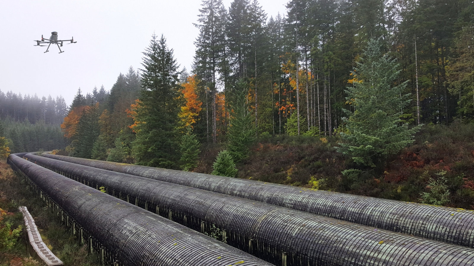
Drone program can help in conducting inspection for oil and gas companies without human intervention

How can Drones with BVLOS Capabilities Help Oil and Gas Companies Secure Pipelines 

Ease of travel between assets

Drone program can help in conducting inspection for oil and gas companies without human intervention

Traveling between assets during inspection operations might become challenging because these pipes can span thousands of meters. The team may be required to travel long distances and to distant regions where there is no adequate road infrastructure.

Operators must travel to the sites, assess the asset, review their data, and then drive to another asset. Furthermore, they must repeat the entire process until all assets have been inspected. This can take a significant amount of time which can be costly for an industry like oil and gas.

However, drones can travel vast distances and reach difficult-to-access locations. Additionally, using drone-in-a-box systems, eliminate the need for continual re-launching, packing, and landing of drones which is majorly faced in manual-led VLOS operations.

Increase worker safety

Oftentimes, assets are located on high terrains or difficult-to-reach locations. Operators may need to set up substantial scaffolding or dangle from ropes to inspect this equipment. Any mistake here can result in severe consequences. Despite the industry's strict regulations and safety standards, health and safety concerns persist. A BVLOS operation eliminates the operator's danger by allowing them to undertake the flight mission from any remote location.

Simplify early detection of pipeline leaks

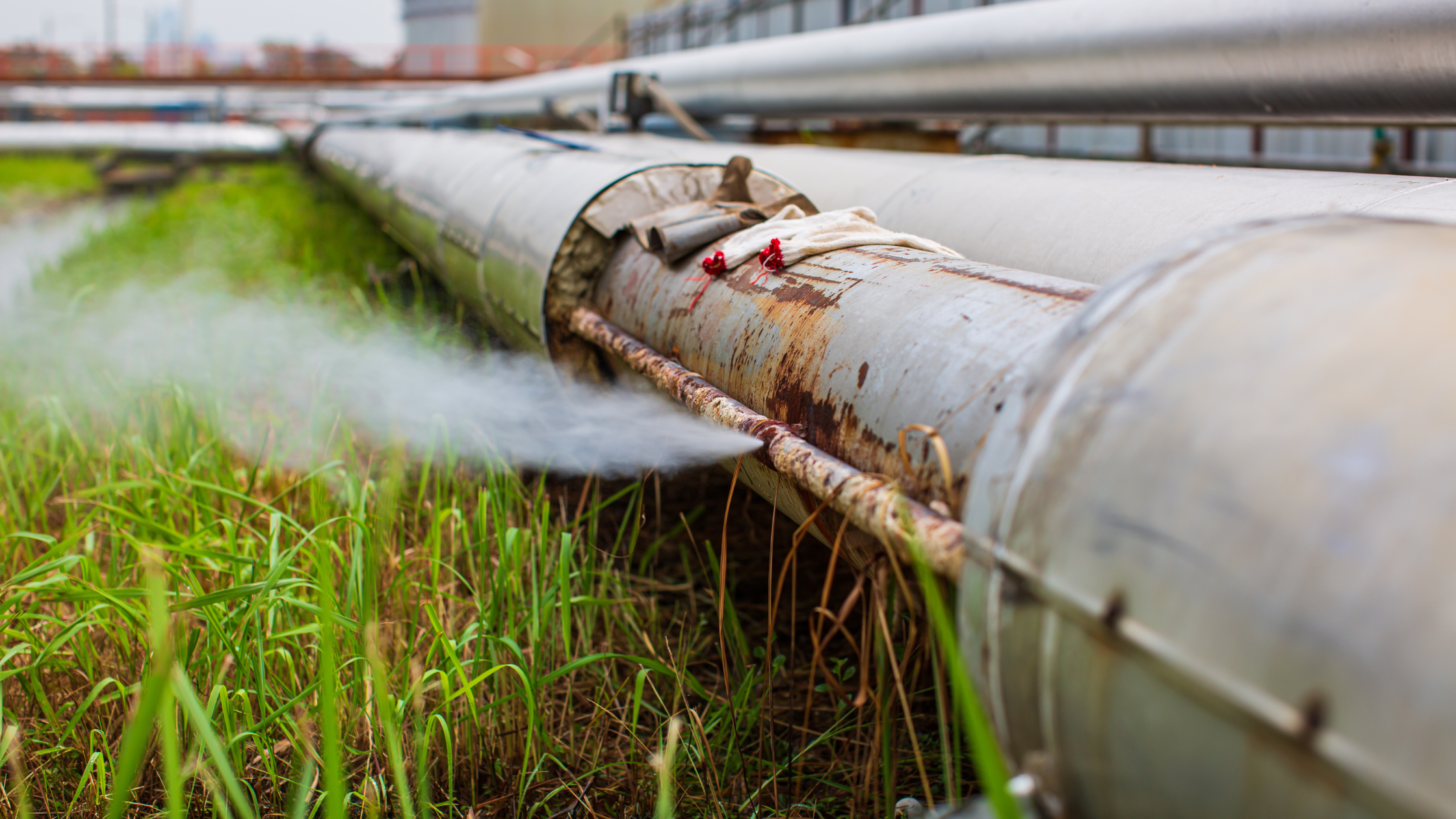
Example of leak in the gas pipeline is affecting the surrounding environment

Drones are increasingly being used in the oil and gas industry for early detection of pipeline leaks. By using advanced drone technology including thermal cameras and visual or infrared cameras, these drones help the operators to identify gas leaks in storage tanks and pipelines with greater accuracy and efficiency than traditional methods.

These drones can easily access hard-to-reach areas and capture high-quality photos and videos of the pipelines and storage tanks. These data can be helpful to conduct image analytics for accurate and early detection of potential leaks or damage.

This allows operators to respond quickly and effectively to potential pipeline failure, minimizing the impact on the environment and reducing the risk of accidents. The use of drones also reduces the potential for human error, as operators can monitor the pipelines remotely, without the need for physical inspections.

Reduce heavy costs

Hiring a pilot and a helicopter, for example, can cost thousands of dollars. Regular inspections may become prohibitively expensive and time-consuming. Autonomous drone missions can minimize such costs while also minimizing human dependency.

Utilize readymade data and analytics via automated procedures

A human-led operation requires the operator to drive to the location and visually inspect the asset. Via autonomous operations, drone operators can run pre-planned drone flights and augment the inspection process. The drone will follow its routine, capture and store data which can be further assessed for detailed inspection as per need.

This enables the operator to quantify their assessment with turnkey data and analytics delivered via automated workflows. This simplifies the entire process and backs it up with data, which greatly aids decision-making. 

Ability to scale operations

While examining pipelines spanning thousands of kilometers, it becomes nearly impossible to conduct manual operations consistently. However, autonomous drones can be scaled up and deployed readily to fit the business's needs as they can be programmed to conduct the desired tasks. 

How FlytNow is Enabling BVLOS Operations

BVLOS operations in pipeline inspection

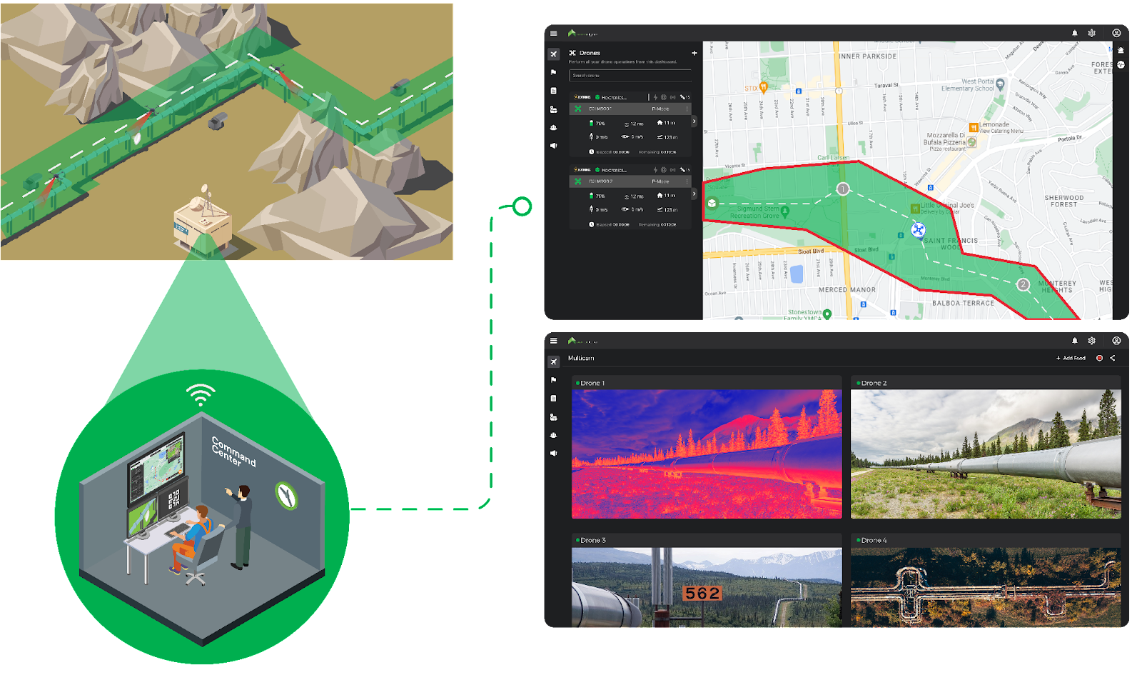
FlytNow is a cloud-based solution that enables the deployment and management of drones in just a few clicks, allowing you to manage your drone operations via a single web-based dashboard for a seamless experience. It helps you lower travel costs, reduce operation rounds, and increase productivity by saving travel time. It is integrated with ready-to-use intelligent modules, like collision avoidance, and precision landing, and integration with drone-in-a-box systems, which further helps you shorten your time to market.

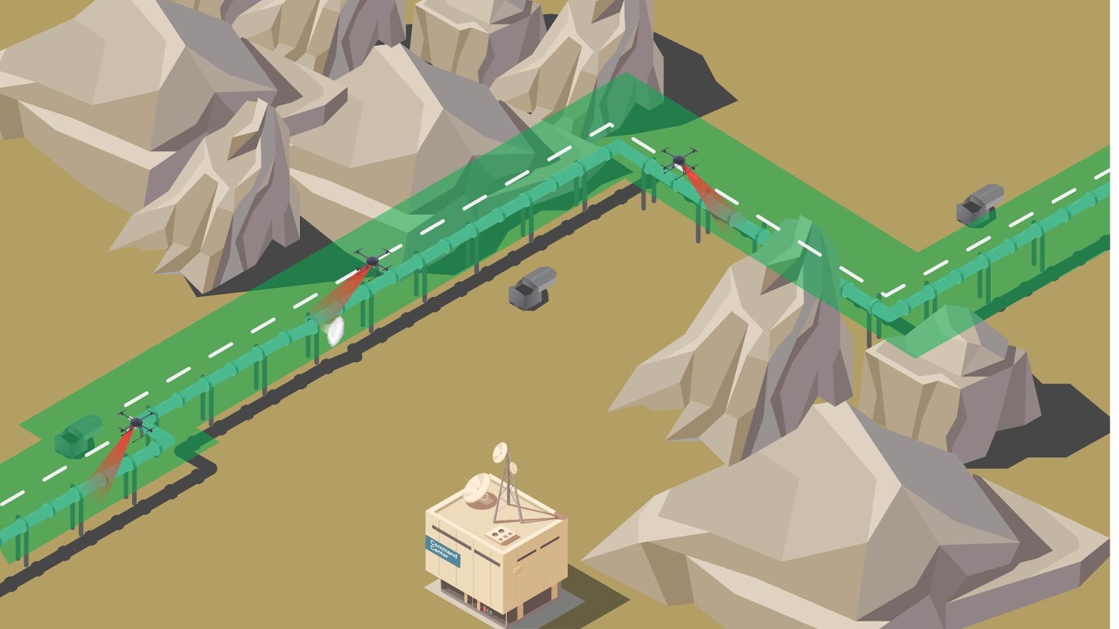
The FlytNow software solution enables project managers to schedule pre-planned or on-demand flights from a command center located miles away from the base station. The drone takes off from the drone nest autonomously, flies its mission, captures real-time videos and images, and uploads them to the cloud.

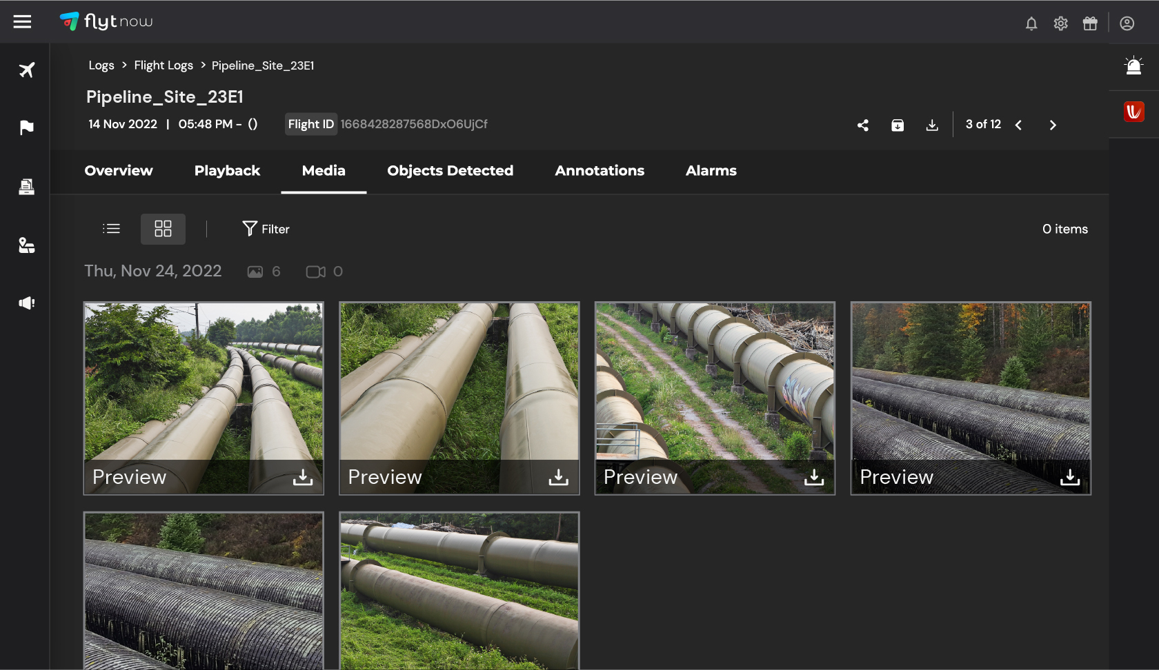
Store images and videos on cloud and Identify leaks on pipelines with FlytNow's solution

Following the flight, the drone returns to the docking station for battery swapping and storage. These stations can charge up to four batteries simultaneously and swap out the existing battery in less than 90 seconds, ensuring minimal downtime. Furthermore, because it is lightweight, it can easily fit on the back of a pickup truck and be moved from one location to another if necessary.

3rd party integrations in FlytNow, such as Casia G system by Iris Automation for detection and avoidance of cooperative and non-cooperative aircraft, Altitude Angel for airspace awareness, and others, assist to increase capabilities for greater insights and seamless BVLOS operations.


Leveraging Nested Drone Systems (NDS)

How nested drone system helping in pipeline inspection

The Nested Drone Systems (NDS) can significantly improve the data collection process and transform how pipelines are inspected. It lets the drone operator conduct long-duration flights without the need to return the drone to the command center to recharge or swap the battery. With the nested drone system, energy companies would be able to quickly scale up, undergo a digital transformation, run safely, and boost productivity.

Nitin Gupta, Founder & CEO of FlytBase, Inc. concludes by stating that “Nested Drone Solutions are rapidly revolutionizing the way repeatable, high-frequency missions are conducted across use-cases. Maintenance of pipelines, spread over thousands of miles, is a great application of this technology with a significant ROI for the end-user.

FAQs

1) How can drones improve the safety of inspections on oil and gas pipelines?

Drones can play a vital role in improving the safety of inspections in the oil and gas industry. With their ability to fly closer to the ground, drones can provide high-resolution aerial data through the use of visual or infrared cameras. This allows for more precise and thorough inspections of pipelines, particularly in hard-to-reach areas. 

By using drones, workers can avoid the potential dangers of inspecting pipelines on foot, such as exposure to crude oil leaks. Additionally, the use of drones allows for earlier detection of leaks, which can prevent potential disasters and safeguard the environment.

2) What are the benefits of using drones for pipeline inspections?

Drones provide several benefits for pipeline inspections, including accuracy and improved technologies. Using drones to detect leaks and identify potential issues can save costs and equipment compared to traditional inspection methods. Drones can also access dangerous terrain and provide quick emergency response. 

In addition, using drones for regular inspection can improve worker safety by avoiding the need for workers to enter hazardous areas. Visual or infrared cameras on drones can monitor pipelines and identify potential issues, whether it be for gas or oil pipelines. With better data and improved maintenance, major accidents can be avoided through the use of drones for pipeline inspections.

3) How can FlytNow help in pipeline inspection using drone-in-a-box systems?

Using FlytNow-powered drones for pipeline inspection, operators can now easily detect any leaks in the pipeline with greater accuracy and efficiency than traditional methods. It allows the team to access difficult-to-reach areas and avoid putting any human in potential danger.

Furthermore, operators can get a real-time video stream of the assets, and also capture high-quality photos and videos of the pipelines and storage tanks. This significantly helps in conducting accurate inspections and detecting potential leaks or damage.

4) What can we expect in upcoming technologies in oil and gas pipeline inspection?

New technologies will include autonomous drones that are packed with a cost-effective platform that will help in inspecting pipelines, provide insight for maintenance activities, and identify human errors. Moreover, they will be equipped with a visual or infrared camera that can detect leaks or damage on its own and inform the team immediately.

5) What are some of the best drones for pipeline inspections in the oil and gas industry?

There are several drones that are well-suited for use in pipeline inspections in the oil and gas industry. Some options include:

  1. DJI Phantom 4 RTK: This drone has a high-resolution camera and RTK GPS for precise mapping and surveying capabilities.
  2. DJI Mavic 2 Enterprise Dual: This drone has a compact design and can fly in challenging weather conditions. It also has a dual thermal and visible light camera for identifying issues in pipelines.
  3. senseFly eBee X: This drone has a long flight time and can fly in autonomous missions to cover large areas quickly. It also has a high-resolution camera for detailed inspection.
  4. Parrot Anafi USA: This drone has a 4K HDR camera and is capable of flying in challenging environments. It is also lightweight and easy to transport.
Read more…

Have you been troubled by many scattered modules and messy wiring in the aircraft cabin?

Have you noticed that inside the conventional assembled drone, the wiring is very complicated,easily wrong connection and difficult troubleshooting? And the scattered modules often encounter incompatibility, cause some functions are unavailable and lower the performance of the whole drone.

As a senior participant in the UAV assembly industry—EFT Company, just launched Z-series integrated module flight control which can effectively solves the above problems.

Below is the video of product assess for your reference.

https://youtube.com/shorts/NvcxPS3m_hE?feature=share

10920843657?profile=RESIZE_710x

Summary of the features :
Integrated modular design, RTK, flight control and receiver can be plug and play, free debugging.
Easy to operate and better waterproof
Neat layout and simplified maintenance
Customized firmware and protocol for smoothly interconnected of whole drone, greatly upgrade intelligent effect .

If you have new requirements or ideas for assembling agricultural drones, welcome to contact us.

Web:www.en.effort-tech.com
Email:infor@effort-tech.com

Read more…

The cost of assembly drones is relatively low, gradually getting popular with ordinary farmers and plant protection service teams.

However, there are some disadvantages of assembly drones, such as low intellegence, complex debugging, messy wiring etc.,which are bother most assembler dealers and service providers.

For above cases, EFT developed the Z series holistic smart drone system solution .
Z series drone solution innovatived in structure,and configured with intelligent linkage system , deep integration of software and hardware, professional comprehensive inspection to ensure the quality . Realized more convenient , more intelligent and precise , more stable and durable.


If you are interested ,welcome to contact us to learn more .

Web:www.en.effort-tech.com
Email:infor@effort-tech.com

Read more…

Introducing Zio | Meet The First Payload of Gremsy

𝗜𝗻𝘁𝗿𝗼𝗱𝘂𝗰𝗶𝗻𝗴 𝗭𝗜𝗢 | 𝗠𝗲𝗲𝘁 𝗧𝗵𝗲 𝗙𝗶𝗿𝘀𝘁 𝗣𝗮𝘆𝗹𝗼𝗮𝗱 𝗼𝗳 𝗚𝗿𝗲𝗺𝘀𝘆 Over a decade known as a gimbal manufacturer. Today, Gremsy introduces a new product; the initial payload is called Zio. The launch of a brand-new line of Gremsy ecosystem. Zio is a high-resolution zoom payload that combines a Sony sensor with high-stabilized three-axis gimbal technology. It enables industrial inspectors and surveyors to zoom into objects of interest and effortlessly transmit video at 4K resolution, ready to be utilized for a variety of different inspection, surveying, and public safety jobs.

https://youtu.be/Ft_EDlH8-SU

- 4K Sensor Resolution

- 30X Super Resolution Zoom

- MAVLink Support

📰Read more about Zio: https://gremsy.com/zio-payload

🔔Pre-order Zio: https://gremsy.com/zio-payload-store

✉Contact our sales: https://gremsy.com/contact

Read more…