All Posts (11086)

Sort by

Adventures with an RC car exercise coach

car03.jpg
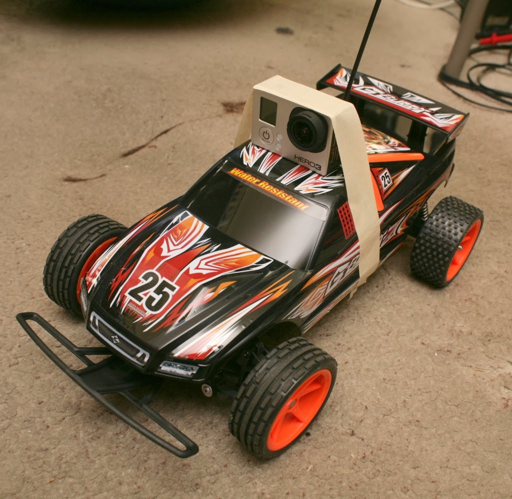
The RC car came along on Jan 8, 2014.  The world was never the same, since.  It was a $40 el cheapo G buggy from Toys R Us.

It was really crusty. The steering was binary. The speed was binary. Instead of a steering servo, it banged a motor completely left or right to the stalling point.

For someone who never had an RC car before, the amount of mechanics required to perform steering & optimally transfer power to the road was quite amazing. 4 wheeled vehicles are pretty complex compared to flying vehicles & there's no simpler way of doing it.   The 2 wheeled balancing robot eliminates a lot of the complexity, but it still can't achieve the ultimate fluidity in turning that fully articulated wheels do.

A manually controlled vehicle might be viable for exercise. A vehicle which carried supplies for 30 miles was on the radar for a while.


The very 1st experiment running with it was a real buster.  The 1st step was to make single handed driving more ergonomical.

car01.jpg

car02.jpg

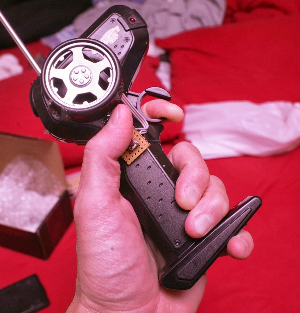
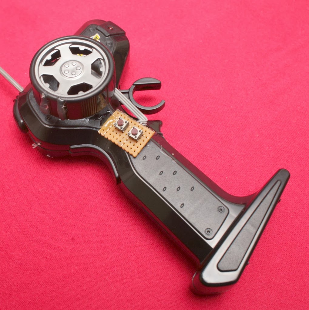
It's not so easy to make driving 1 handed. The stock controller seemed almost designed to make it barely possible.  Some hot glue blobs on the steering wheel made it easier.  Binary steering buttons reduced the stretch even more.

rc_run.jpg

Ran 7 miles with the RC car being manually controlled this way.
Interesting to note how the speed followed the NiMH discharge curve for 7 miles.


Keeping it on the narrow urban sidewalks was impossible. After leaving the urban jungle, it could start staying on the 15 ft wide trail. After several miles, banging out a straight line became automatic. Its tiny wheels made it erratic on the crumbling parts of the trail. 1 handed driving was still difficult, but better. The hand controller needed to get smaller.


The gopro naturally died after 6 miles. The RC car went 7 miles on its 6 1.5Ah NiMH AA's, then suddenly died & had to be carried 6 miles home. That was way beyond expectations. Thought it would go 1 mile. 6 miles on 1.5Ah should be considered the range on NiMH AA's, with a camera. It has a brown out shutoff. A brushless motor might get it up to 9 miles.  Its nominal pace was 9m30s.

This system was fast enough to be a pacer for a slow, long run, but needed more NiMH batteries which are super expensive compared to Lipo. Wanted to only invest further development in a high end brushless system. Those things are expensive, even from Hobbyking. They're $75 - $100 just for the frame.

lion01.jpg

lion02.jpg
 
lion03.jpg

Lion after 6 miles. There's no way to see yourself this far from home besides robot.

Don't think the changes were substantial enough to sell a manually controlled, modified RC car as a workout coach. The only differences would be the 1 handed control, longer range, & attachments for water.

Making it completely autonomous was pie in the sky, but there might be a way to get it to drive the straight sections or avoid obstacles. A camera which automatically tracks the runner would be something. There's absolutely nothing which can make a timelapse video of an athlete during an entire run, but it can't be far off.


The next run was 5 miles with the camera mounted backwards, to analyze running form.


Its speed was 8m30s/mile for the 1st 3 miles. Then it regressed back to 9 minutes per mile.  Since the timelapse was 20x, it was good evidence of a 180 cadence.


lion05.jpg

The camera documented the gender gap nicely.

An RC car could be a decent way to improve running, if only there was a budget to build the right RC car. There was no plan for any more running with this one.

Proportional steering & speed control would be the minimal starting requirements. The current vehicle could probably be given a new electronics board with 12V Lipo support, back EMF regulation of the speed. The steering motor could probably be swapped for a servo, but destroyed in the process.
car01.jpg


It was decided to continue tearing the RC car down into an exercise tool.

car02.jpg

car03.jpg

car04.jpg


car05.jpg

car06.jpg

car07.jpg

car08.jpg


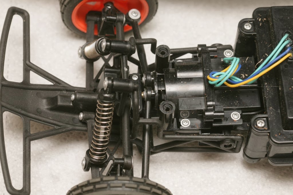
 A rod could be attached to this plastic plate for a servo to pull. There was enough clearance on the studs to fit a thin sheet of metal in front of it.

car15.jpg

In the best case, the gearbox would have a hole cut open. A lever would be fitted to the mane rod, which a servo would pull from outside. The only other idea was to restore the original gearbox, use the original motor, but fit a hall effect sensor outside to detect the position. It would take a lot of energy, since the gear ratio wasn't high enough to hold the wheels without actuating the motor.


car09.jpg

The mane board was a standard design analyzed by thousands of RC hobbyists. Nothing on it could be used in a new car design, though it had useful parts.

car10.jpg


car11.jpg

car12.jpg

car13.jpg

car14.jpg

The electronics enclosure could be shaved down 1/2". It was too structurally important to shave it all the way to the bottom. A flat plywood sheet could cover everything. It would be very top heavy. Achieving controlled steering was the great task.


car16.jpg

The RC car went to heroic lengths to achieve just bang bang steering.  That giant piece could be replaced by a much smaller servo, but it's been produced since 1980 & probably costs 10 cents.

car17.jpg

It didn't completely stall the motor, despite the motor sucking very high current when at the limit. It used an ingenious centrifugal clutch.


car18.jpg

The 2 hemispheres spread out when the motor speeds up, engaging the gearbox. When the steering maxes out, the clutch slips. When the motor stops, the clutch disengages, allowing a spring to force the wheels back to the center.


car19.jpg

The plan was to use the existing geared motor as the heart of a servo. There was no practical way to install a hobby servo for steering. The 1st step was to fuse the clutch to the gearbox so the wheels would not freely move when the motor stopped. This probably couldn't be undone.
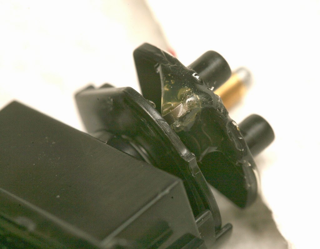
car20.jpg

Next, we had a magnet hot glued on the steering horn. It was hoped that a hall effect sensor could detect the magnet's position precisely enough to control the motor.

A quick test revealed it would take more like 8 hall effect sensors to do the job. Their range, even for the 5mV/gaus version, was too short. It wasn't the most elegant solution, but the cheapest. Just a matter of stretching the range as much as possible. A magnetometer would probably not do the job, since it would detect the Earth's magnetic field.

Attention turned to making 1 handed driving more ergonomic.  Wearable RC control is a problem as old as time, we all encounter eventually, especially now that the venture capitalists have latched on to wearable computing.

Today's problem is proportional steering & throttle with 1 hand.  The solution begins by tearing down a picco Z controller for sticks.  It would be ideal, since it was rugged & used single axis sticks.  There's no chance the 8 year old controller would ever be used again.


car21.jpg

control01.jpg

control02.jpg

Sadly, it didn't use potentiometers. Those were encoders. They needed a very complicated circuit to decode & the lack of precision was why the Picco Z was so hard to fly. It must have been a lot cheaper to use these encoders & a complicated network of diodes than a proper pot.


control03.jpg

The next step for throttle was from a spinmaster from 2009. Progress had reached the point where a toy could afford a true pot. What a miracle, in the toy business.


control04.jpg

To get the proportional steering, the only analog solution was a modern joystick from a Syma X1. Those are still quite an investment compared to the 3 channel copters, so a 2 axis joystick is still a small miracle for a toy.

control05.jpg


The problem was arranging the 2 controls to fit 1 hand. This was traditionally done by mocking up the controls in clay or playdough.

84652_MIArcher_03.jpg


128691_D_L.jpg


The last time someone mass produced a single handed RC control was in the Silverlit MI Archer & MI Hover. They used tilt sensing.


The matter of speed control was heading towards a buck converter supplying a constant voltage to the motor driver board.  There wouldn't be any feedback loop to compensate for ascending & descending.  It would be very hard to get constant power out of PWM.  Linear regulation was always frustratingly inefficient.

buck02.jpg


Work began on a buck converter made out of spare parts.


buck03.jpg
The home made buck converter was most efficient at 120Hz.  It peaked at 9V 2.3A.  To make that, it consumed 12V 2A for 82% efficiency.

The car needed 7.5V 1.5A.  Lacking a real dummy load, it produced 7.5V 1.9A by consuming 12V 1.7A for 70% efficiency.  The MOSFET still heated up over 75C.  The efficiency was probably overstated because the load resistance was not accurately known.

The dropout voltage at nominal use was 3V.  It was a much worse dropout voltage than an LM317.  A pair of LM317's with a big heat sink would do the job in much less space.  They have a 2.5V dropout voltage & heat to below 50C while providing 8V 1.7A.

A linear regulator would be 62% efficient.  The circuit was definitely not the most ideal, probably owing to the MOSFET being extremely slow. A  Castle 10A BEC could do a whole lot better in a lot less space, but this was the age of spare parts.  Castle still required a $25 castle link programmer to get 7.5V.  RC hobbyists are just not a market that reverse engineers electronics.

car_remote01.jpg

Many experiments with wood & hot glue revealed a decent hand controller arrangement.  A wheel was better than a stick for steering.

car_remote02.jpg

Some hot glue added grip to the steering wheel.  Unfortunately, the pots had a finite number of gluings.  There was no other way to attach the pots than with a giant blob of glue.  The throttle stick wanted to angle away from the camera, which would require a heavier piece of wood.
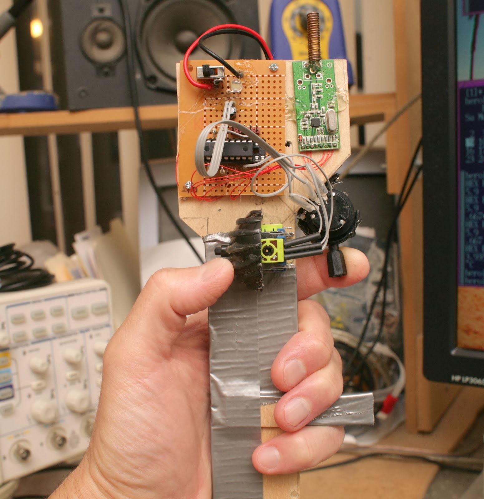
car_remote03.jpg

The functional version, without battery.  Now it was time to bang on the RC car electronics.
 

car11.jpg


The easiest solution was to reuse as much of the stock circuit board as possible.  It had a current limiting resistor, caps, & H bridges matched to the motors.

Connections:

Vss, B+:  battery connections


R4, R5:
drive motor H bridge control
3V active 0V inactive
pulled down by 100k resistors


R6, R7:
steering motor H bridge control
3V active  0V inactive
floating, but driving a BJT H bridge


M1: drive motor output
full battery voltage


M2: steering motor output
full battery voltage


Because the stock microcontroller was glued in place, it had to be removed by lifting the pins.  Hot air delaminated the board before it came off.


New connections:

3 ADC: hall effect sensors
4 PWM: H bridge control


With the board prepared, studied various hall effect sensor arrangements for the steering.  It would take 7, basically filling the entire travel with side by side hall effect sensors of at least 2.5mV/gaus.


Unfortunately, there was too much play in the gearbox & axial movement in the shaft for any kind of hybrid servo to work, with any sensor.  The wheels would never track with that amount of gear play & the hall effect sensors couldn't get a reliable reading with the shaft moving axially.


The default spring mechanism with centrifugal clutch was precisely optimized to drive in a straight line.  So with the steering reverted to the stock configuration, there was 1 final test to apply variable motor speed against the spring to try to get some kind of manual proportional steering. 

It seemed to work when moving away from centerline, but the wheels would not return until the motor stopped completely.  Fortunately, most steering would be very fine tweeks near the centerline.  The manually guided proportional steering idea was a matter of building & testing on the road.

car23.jpg

Fully proportional car electronics finally started working. Throttle was now proportional & very controllable.

Steering was still very hard to control, but had some latitude where there was none before. There were basically only 2 positions you could get from the joystick: fully deflected & slightly deflected. It might improve with a lookup table instead of a linear taper. Steering might still work better with tact buttons instead of the joystick. Any change in the mane voltage would require changing the lookup table.

car22.jpg

Bare minimum dual linear regulars flawlessly provided the constant power.  A PIC converted radio packets to motor control.


car24.jpg


The mane board was hacked with hot glue to keep to the delaminated board together.   The PWM frequency for throttle was 30Hz. For steering, it was 60Hz. It worked well enough.

After much troubleshooting, it was found that the 433Mhz 10mW RF output from the radio skewed the PIC's internal oscillator high by a certain amount. It increased the transmitter baud rate by a fixed amount, but increased the receiver baud rate depending on distance. The transmitter had to be a minimum distance from the receiver to work. Even then, there was a certain instability in the amount it influenced the transmitter baud rate, limiting it to below 9600.

Packing everything up & installing the batteries was still a big unknown.


car25.jpg

Packing everything up ended up being a system of pieces of wood of various heights to attach to the 6 existing hard points.


car26.jpg

After all that work, 2 of the hard points ended up inaccessible, so they were left unattached.


car27.jpg

Then a 2nd layer went on for the camera.

car28.jpg

car29.jpg

It was a mess, but affordable.


Ran 4 miles with the RC car. The ergonomic hand controller was a joy. It was like the car was an extension of your body.   Too bad the status quo in commercial products was too big to fail. The radio worked perfectly.


The throttle worked nicely. The steering was still worthless. It was too inconsistent. The next step would be 2 steps only, with hard coded PWM.


The battery finished at 11.7V. It took 2Ah to go 4 miles. At 7.4V regulated output, it did 8m30s miles downhill & 9 minute miles uphill. This seemed to be the motor's most efficient speed. The voltage regulator was perfectly matched to the heatsink.

All the improvements only made the speed more stable. The range was greatly reduced.


The battery sliding out & roll overs were problematic. The battery straps served no purpose. The camera definitely had a sympathetic oscillation. Another gopro firmware crash robbed most of the footage.


car30.jpg

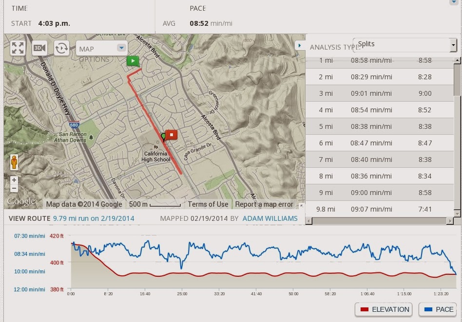
Finally did a range test with the RC car by running up & down a 1/2 mile segment of road. That was really hard. The voltage was regulated at 7.4V. It went 9.5 miles at a constant 7.1mph downhill, 6.7mph uphill. Speed quickly faded after 9 miles.

The recharge was 85 minutes at 2A. The run was also 85 minutes, giving 2A of consumption. This 8 year old battery was originally rated at 3.3Ah & still had 3Ah of capacity, if run all the way to destruction at 2A.

So the speed was constant but the range was only 2 miles longer than stock 1.5Ah AA's. It put a lot more wear on the tires than stock batteries. It was practical for a tempo run, but not for a long distance movie. The voltage would have to be reduced, which would require another range test. The long distance movie would be more easily done with an unregulated 2S battery than a regulated 3S battery.

It still took a lot of energy to drive & run simultaneously, despite the ergonomic controller. It was also after running 4.85 intense miles the day before. Turning around every 1/2 mile probably made it harder.

It was interesting to note the elevation change on that course was only 45 feet, yet had a significant impact on the car's speed. The challenge in running uphill on that segment was not just psychological.

Foam under the camera greatly aided the oscillation.


An RC car modification used 2 fixed voltages for steering. This worked better than any other method, but it was hard to know when the stick was doing anything. 4 buttons might be easier than the joystick, but it's convenient to have full deflection right there.

2 voltage steering was better, but far from perfect. There were times when the low voltage wasn't enough. When it hit a rock or a crack, it needed more correction.

A straight line driving algorithm would be nice. For all the applications of GPS, you would be hard pressed to make a rover drive in a straight line by GPS. A path following algorithm would be very difficult, but more worthwhile than GPS.

car32.jpg

car33.jpg

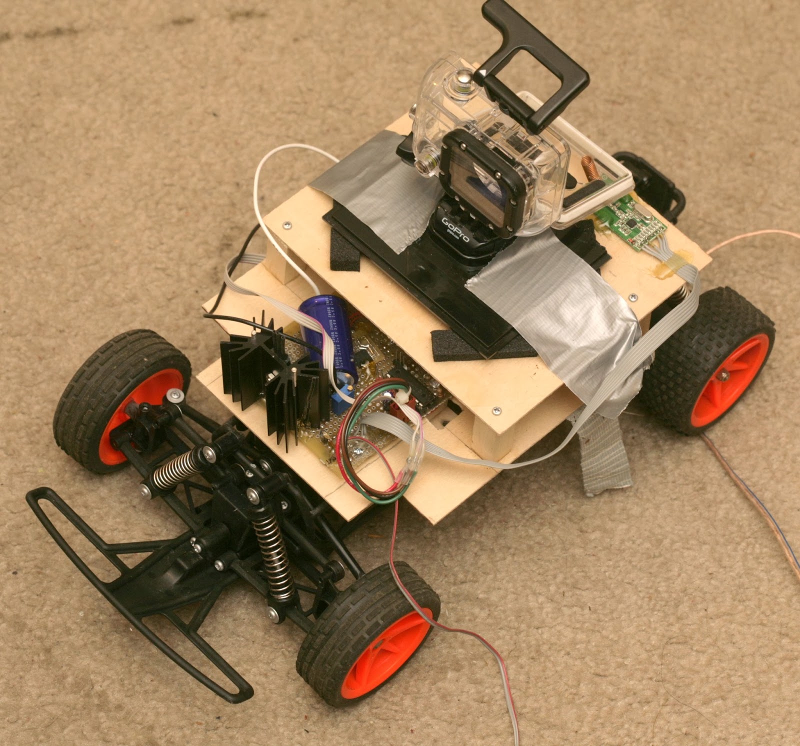
RC car heading hold was a tale as old as time, but no-one did it for the least cost. Put in a simple analog gyro & P feedback algorithm. There was just enough proportionality in the steering mechanism for it to work quite well.

Didn't bother with I feedback, since it would suck battery power to constantly drive the steering motor. The steering was so imprecise, it always oscillated around the desired heading. The heading drifted noticeably. Upgrading to a full IMU would require a new CPU.


After much tuning of the gain, it could go without manual steering for a bit longer than before, but still required significant attention. Rough road was now effortless to drive over. It came a long way from its stock $40 ways, with only a crusty old microcontroller with only 256 bytes of RAM.


car31.jpg

The 5 year old pot began its decline. It definitely needed to be mounted diagonally.

The heading hold was supplemented with steering by wire so a half stick deflection would change the target heading but not directly command the motor. A full stick deflection would bang the motor all the way over & read the new heading. It only activated steering by wire when throttle was active. With no throttle, only full stick deflection did anything. That overcame most of the limitations of the bang bang steering to keep it in a straight line.


Its 1st test was after a day of RC car testing.  Keeping up was a real fight, even going downhill. GPS reported it doing only 8m40s miles. Had it at full throttle for a very difficult 6 miles, then hit the wall.

Walked for .4 miles, then slowly ran for 2 more, when the battery died after only 8.2 miles. Heading hold obviously sucked a meaningful amount of power. The throttle could be easily modulated to give an 11 minute pace.

That brought its total mileage to 36.6. The front wheels got rotated. It was probably way beyond the normal life of these $40 toys.

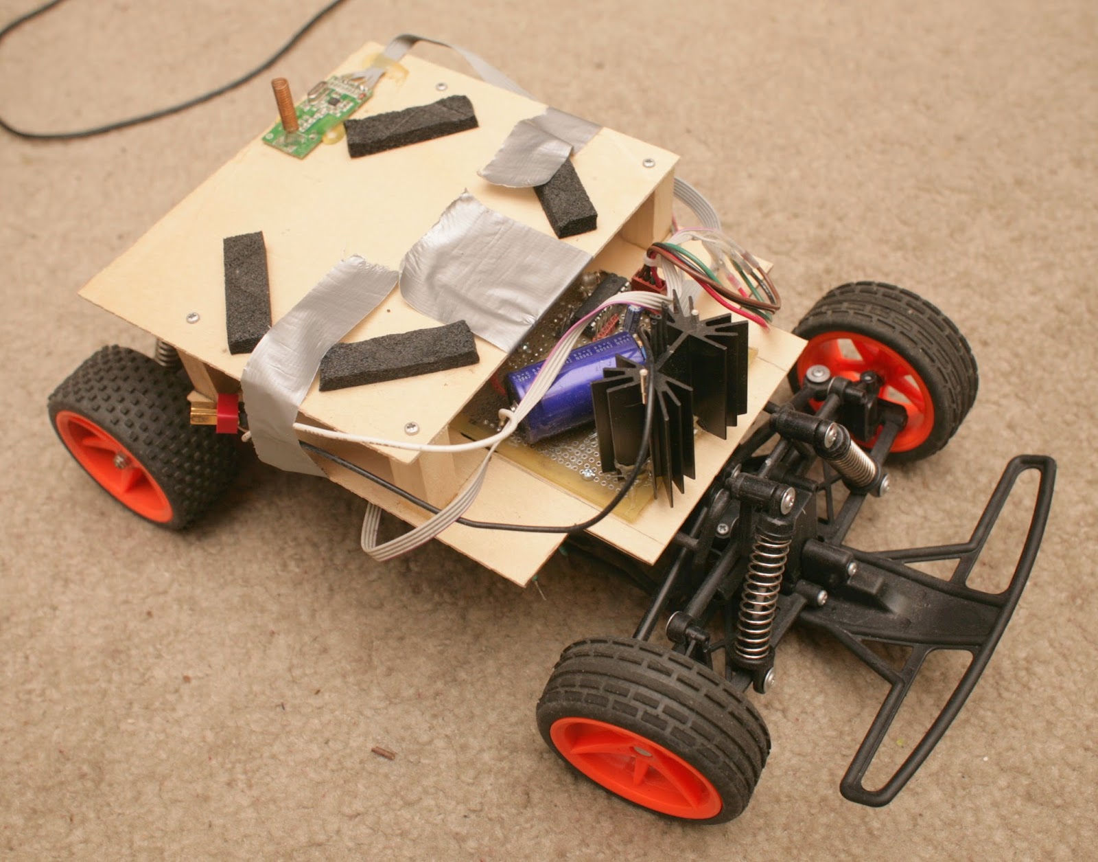
car34.jpg

car35.jpg


For the 1st time, ran with the RC car fully empty, 3Ah battery, 7.5V, until battery exhaustion. Without the camera, GPS showed it doing 8m10s miles uphill & downhill.  Tire wear was much less. It still completely died when the battery died after 10 miles. It averaged 8m30s miles for the entire distance & 8m10s for 5 miles.  It was much easier to drive without having to realign the camera after every bashing. That test contained the fastest 5 miles ever.
 
Whether or not its effect was only psychological, all the improvements to the RC car did seem to improve fitness.  Hitting 8m10s per mile for 5 miles would be really hard without it.  That brought it up to 53 miles.  
 
Making it fully autonomous would still require a much bigger vehicle, with a lot more sensors.  There would be lidar, cameras, a faster computer, a lot more battery power.

Read more…

3DR X8 RTF Unboxing / Test

3689588828?profile=original

A lot of people have bought the RTF 3DR Iris as there is a plethora of info out there on both performance and modifications.

The X8 is the heavy lifting RTF option and is a little less common.

I've been an Arduplane fan for about 3 years now, starting with the APM 1 in a Skyfun and working my way up to an APM 2.6 in a Skywalker X8 complete with Cellular Telemetry over 3G.

I've never been into copters as much but I thought it was about time I checked out what all the buzz was about and share my experience here.

I bought a cheap quad online for $100 with the intention of learning to fly quads and wrecking a cheap one before letting loose on something a little more expensive.
After getting to the point where I could just about turn the thing inside out, I thought it was about time to upgrade.

I did a lot of research on the DJI vs 3DR and then looked at the Iris.
My thinking was that the Iris is a nice toy but its not really worked up for doing anything too serious, that left the Y6 or the X8 and I eventually decided to go all out and order myself an X8.

I also needed new radio gear as my old Hitec radio was showing its age so I added in a D7 radio, full telemetry kit, spares and a Gimbal all from 3DR to support the cause.

It went on back order with around 2 weeks after ordering before it shipped which was acceptable.

Then the fun began with shipping. For some reason the shipment got held up in Memphis. I left it for a few days then made a call to fedex who weren't much help.

3689588910?profile=originalNext I dropped a line to 3DR to see if there was anything they could do and after about a day to respond they managed to work some magic and the package began moving again.

3689588862?profile=original

When the package finally arrived it had an "Opened by New Zealand Customs" sticker on it. This always makes me nervous as you half expect it won't get packed back in as well or that something would be damaged during the premature unboxing at customs.

Opening the box, I was a little surprised at the internal packaging, it wasn't exactly a stellar packing job given the journey that box had taken, however there is no way of knowing whether this was the way it was packed by 3DR or whether the re-pack at customs was less than stellar.

However the good news was that nothing was obviously broken and the copter itself was placed in such a way to minimize the chance of any breakages.

3689588954?profile=original

 The X8 itself had foam protecting the motors, plastic wrap over all aluminium parts to avoid scratches and one leg was folded in to maximize the space available in the packaging.

The first thing that strikes you about the copter is its size and weight. This is not a toy and everything is constructed with heavy duty components while minimizing weight.

The second thing that strikes you is the fact that if this thing goes down, due to its weight its going to be a write off.

Extreme care will be the order of the day when flying it. Its certainly no acrobatic machine and you can see how its size and weight lend itself perfectly as a camera ship.

There are also some nice touches that make it a true RTF option for someone who doesn't have the build capability to put together their own ship. The LiPo Guard pouch for charging the batteries is a great idea and the included charger while towards the bottom of the quality range is more than adequate for most needs.

3689588935?profile=original

One thing that becomes apparent once you have everything laid out is the lack of things to actually put together. 3DR advertise this as a RTF kit which I was skeptical about and was expecting to spend at least a day building it, however it really is ready to fly with only minor assembly.

Nevertheless I took the time to check over the entire unit, tightening screws, applying loctite and double checking everything.

Connecting it to the mission planner was straight forward, and all the settings were dialed in and ready to go for the airframe. A firmware update was needed to bring it up to the latest version and because I am new to Pixhawk I had some head scratching before I discovered you need to press the safety button when loading firmware.

3689588888?profile=original

I decided to fly it without the Gimbal initially in case there were any mishaps.

So how did it fly...

Well pretty much perfectly.

Stabilize was as solid as a rock. I fully expected to spend the entire first flight battling to keep control of it while modifying PIDs, but it gently lifted off the ground and sat in the air perfectly stable.

Flicking it into Alt Hold mode yielded similarly successful results. I took it for a wee spin to test its responsiveness and was impressed by how rock solid this ship is.

I was feeling so confident about its performance so far I did a quick double check that it had GPS lock and then dropped it into Loiter and there it sat.

Since then I have dumped about 6 batteries through it and I continue to be impressed.

Next step was to add the gimble and take it for a spin with a GoPro.

This has been the hardest part of the whole process, tuning up the Tarot Gimbal can be quite a challenge and a novice would certainly struggle with it. It took me about 2 hours to get a nice smooth config. The settings I needed turned out to be completely different from some of the configs posted on the internet, however once its setup it really is a nice Gimbal.
I will post some shots from the GoPro once I take the X8 for a flight with the Gimbal attached.


In summary, the 3DR X8 2014 edition is a rock solid camera platform suitable for professional use.

It really is RTF but I would not recommend it to someone who has no experience either flying or with the APM. There are simply too many things one could get wrong that could dump this air-frame into the dirt.

This is the perfect system for someone that:

  • Already has experience flying an APM or Pixhawk based plane or copter
  • Doesn't have the time required to put together a large X8 copter or doesn't have experience building models.
  • Wants a heavy duty camera platform

Hats off to everyone at 3DR, you continue to improve with leaps and bounds and credit where credit is due, the X8 is a formidable piece of machinery.

Read more…
3D Robotics

The Canadian regulators are rightly investigating the above video, which seems shockingly irresponsible. From Global News:

VANCOUVER – More than five months after a YouTube video was first published, concerns are growing about possible conflicts between drones and aircraft.

Drones are unmanned aerial vehicles (UAV) and are soaring in popularity.

However, a video posted by ‘Quadrotor Dragonfly’ shows a remote-control drone shooting video of a jet landing at Vancouver International Airport. The drone appears to be at about the same altitude as the jet and not very far away.

Transport Canada regulates drone use in this country and is trying to track down the owner of this one.

“Air Canada 777 observed a small helicopter, he thought it was a real helicopter,” said Bill Yearwood from the Transportation Safety Board. “But when he got closer he realized it was a remote control helicopter.”

He said encountering something like this on final approach in a jet can be disconcerting, if not outright dangerous.

“Quite a sophisticated toy,” he added. The technology is quite good, it makes it easy for somebody to operate and it can operate far away from that person, so that combination can present a hazard if used by irresponsible operators.”

In an email statement from Transport Canada they said:

“Transport Canada is aware of the videos posted on YouTube showing a unmanned air vehicle (UAV) flying near Vancouver International Airport and Vancouver Harbour.

Transport Canada is very concerned about the operations of this UAV and we have been working with the RMCP to determine the operator’s identity. We are continuing to investigate the incident. We urge anyone with information on the videos to please call Transport Canada or email the Civil Aviation Issues Reporting System to report this or similar incidents.”

Yearwood said even if a jet engine ingested a drone, it probably wouldn’t cause a crash as the jet could keep flying on the other engine, but they do not want to investigate any aircraft / drone collisions.

Read more…
3D Robotics

New Spektrum drive-by-wire RC car controller

3689589245?profile=originalAVC (Active Vehicle Control) is a very interesting new product from Spektrum: a RC car controller that adds driver-assist intelligence, including heading hold and throttle assist. The interactive website demo is fantastic, and shows what it can do far better than I can describe here. We already do some of this in the ArduRover code, but this seems like a good opportunity to follow this example and incorporate these sort of features and more (such as automatic drift mode) in the next release. 

It costs $250 and is only recommended for the Horizon Hobby Vaterra Hälix and Losi Rally-X cars for now. 

Read more…

The Business of Drones: A Tale of Two Cities

3689589096?profile=originalThis post looks at who will dominate the lucrative civilian drones market - the giant defense contractors or the small innovative start-ups.

The year was 1775.

“It was the best of times, it was the worst of times, it was the age of wisdom, it was the age of foolishness, it was the epoch of belief, it was the epoch of incredulity, it was the season of Light, it was the season of Darkness, it was the spring of hope, it was the winter of despair, we had everything before us, we had nothing before us, we were all going direct to Heaven, we were all going direct the other way.. “

Ah, the famous opening lines of A Tale of Two Cities. The Charles Dickens passage seems to create a sense of sweeping possibility: the age is everything and nothing at all. Examined closely, the passage also suggests that this is an age of radical opposites with almost no in-betweens. And that is how I would characterize the current state of the small drones business – radical opposites. On the one hand you have the large public defense-related drone contractors like AeroVironment , maker of the Raven, Puma, and Shrike, looking now to capture commercial opportunities in the civilian market. For our purposes they represent the London royal establishment. On the other hand, you have the small private startups like MarcusUAV and Vorobetz looking for a chance for liberty from restrictive air space regulations. They represent the Paris freedom fighters.

Just as in the novel, each city had its own drama and naiveté, so, too, do our players. While everything’s coming up roses in London, everything’s coming up dead in Paris. In fact, in Paris they are so unhappy that they’re beginning to band together as ‘citizens’ of a new republic. They are at their core a revolutionary group. But we can’t tell that they’re revolutionaries, because they’re super-secret. For the most part, they operate their businesses in an underground – as you will see.

Read more here: http://droneanalyst.com/2014/03/07/the-business-of-drones-a-tale-of-two-cities/

Read more…
Moderator

3689589217?profile=original


Dear Friends,

Today we going in production with the first batch of micro brain 5.1 board. After see some micro drone based on vrbrain fly , we decide to support the development of this great platform ... so we start to develop a special revision of VRbrain 5  for this kind of products where the small dimension and low weight are very important factor.

Our user like a lot the drone log because can doing check and understand better how the drone fly : best speed , best flip , rally ecc ecc ...

This is fully total autonomous platform available for micro drone.

These are the specification : 

CPU STM32F4 VR OS based on NuttX kernel.

1 EEPROM or FRAM device for parameter storage. 

IMU MPU6000 SPI.

MSIC Barometer 10 cm resolution.  

8 PPM Radio RC Input .

8 PWM ESC - SERVO Output.

1 SBUS Radio Input compatible with Futaba SBUS and Spektrum ,too

1 SBUS Servo Output.

SD Card Reader 

1 RGB LED 

2 LED Output 

1 Buzzer Output 

On board telemetry module availabe at 433 / 868 mhz. (option) 

connector for external VR GPS + MAGNETOMETER

dimension 4x4 .

native support of APM Firmware : 

APM Copter 

APM Plane

APM Rover 

Custom firmware available for boat and Paramotor Drone.

I think that special new mode ad hybrid loiter and drift are very interesting for these great toys :) 

some example of micro drone developed by Tommyleo , AleBS , Skud85 and other great pilot :)

 3689589190?profile=original

3689589230?profile=original

3689589145?profile=original

Some info and example are available on italian forum baronerosso :

http://www.baronerosso.it/forum/modelli-multirotori/303284-idee-per-un-frame-da-micro-quad-fpv.html

This is the video doing by Bandit with a micro squid 

original blog post : 

http://www.virtualrobotix.com/profiles/blogs/secret-picture-from-vr-lab-vr-micro-brain-5-1-is-coming-the-micro

for info send a mail to : 

info@virtualrobotix.com

Read more…

3689589077?profile=original

Is any work being done by the development team to add this class of vehicle to the capabilities of the APM or Pixhawk series of autopilots?   The Arcturus design is very nice and looks like a very useful cross between Multi-rotor and normal aircraft designs.

here is a link to their site - http://arcturus-uav.com/index.html

dennis

Read more…

3689589105?profile=originalThis is a continuation of previous blog posts about how 3D reconstructions work. In this image you see a dense reconstruction of the same data set used before. I removed points that have less than 3 matches. You can see gaps where there were trees. Vertical surfaces also have very little data because they are typically in the shade and therefore have poor gradients for matching.

An interesting detail is that I processed the same dataset in visualsfm as well and I actually got a lower-quality result there. The main issue with that output was that the radial distortion parameters weren't estimated correctly. Fortunately, you can recognize such cases, because the point cloud has an overall arcing shape. You can still see that also in this data there's a slight arcing effect, as the roof isn't 100% straight, it sort of arcs over.

When that happens, the densification process has much more difficulty in generating the point cloud and it only generates 30-40% of the points that it would generate in other cases. In other words, the better the estimation of camera parameters and the positions, the better the results of the densification. If you work with visualsfm, you should pay attention to that arcing effect.

As a final step, it's possible to generate an orthophoto from this data. There are actually two main strategies for creating orthophotos. One is through homographies and concatenating them together. A homography describes a relation between two photos that have overlap. You can then apply a transform to every image and insert the results in a work image, the final orthophoto. Such ortho's are iteratively created and when you apply blending to it and exposure compensation and the correct warping algorithm, you get results like this, similar to MS ICE:

3689589045?profile=originalIt looks very nice, but there are mismatches in the data, for example the hedge at the bottom  and the slight mismatch near the road and the shadow of the shed. You can also see how this method prunes data of low confidence and just leaves it out of the image. So if you have poor overlap or images with different exposures, you should expect poor matches and more artifacts in the end result with this method.

In the example below I ran the surfacing algorithm to generate a 3D mesh of the area and then reprojected the original photos on that mesh. The mesh is then viewed from an orthographic projection from above, hence "orthophoto". This strategy should theoretically yield better results because perspective issues are more reduced (it would simply project pixels of a wall on a vertical surface which later should be invisible). That only works though if the model has a good estimation of height and vertical surfaces. In practice vertical surfaces aren't reproduced very easily, as these are usually in shady areas, which makes matching difficult. You'd typically get blobby artifacts around such regions. Here you can also see that in areas where the height of the 3D model was estimated poorly, you see an overlap between images, because the pixels get projected on either side on the ground. The roof of the shed demonstrates that issue.

3689589064?profile=originalThis image doesn't look as nice as the first one because it didn't yet apply a strategy for blending and exposure compensation. In areas where the 3D model is poor, you'd expect artifacts. This happens primarily near the borders.

As a final note... in a deliverable of data you typically also have a digital surface model. That can be created very easily from a 3D mode as well by simply testing the height of the data at each pixel of the image. It is essentially a "depth map" of the data.

Read more…

Keeping things toasty in the stratosphere

3689589025?profile=original

Anyone out there involved in High Altitude Ballooning (HAB) operations might be interested in the space-grade Polyimide Thermofoil flexible heater rig we're using to keep our Vulture 2 spaceplane's rocket motor toasty at altitude.

The propellant doesn't much like the cold, so we need to keep it above -5 degrees C if possible - the minimum guaranteed firing temperature.

3689589054?profile=original

3689588985?profile=original

The last snap is the heater sealed onto our Ceasaroni 54mm 3G case with heatshrink, and the no-expense-spared $10 aquarium thermostat is to prevent the heater from melting down at altitude, where its mighty 2.24W output can't dissipate.

While the heater is only capable of raising the casing temperature 5 degs C above ambient on the ground, it's a completely different story in the air, or the lack of it.

A recent test flight confirmed the rig works as expected, and will keep the motor nice and warm. There are full details here.

Read more…

Brushless Gimbal - Opensource communication problem

If you are having problems with uploading firmware or communicating with the gimbal software (RCTimer - Gimbal controller board for example) then most likely the following info will help you.

See communication problem below in Arduino:

3689589119?profile=original

Follow this link for instructions:

https://www.olimex.com/forum/index.php?topic=2031.0

Remember to update both the "serial port driver" and the "USB serial converter" driver.  You will have to update driver, select the browse button and then pick the driver (have disk option), else windows will always take the latest driver available.

Driver link:

https://www.olimex.com/Products/_resources/FTDI_drivers_2.04.06.zip

Trust you will find this useful as I did.

Greetings,

Hein

Read more…

Breguet-Richet-Gyroplane.jpg

The french team behind the "Walking with a drone project" is seeking a drone constructor partner.

This original walking performance should receive a large media coverage.

We will offer:

  • free advertisings to promote our partner brand throughout the world and especially in France (a market with a mature UAV legal context) 
  • and high quality original communication materials, including royalty free videos, pictures and testimonials,...

Feel free to contact us

We are very happy to announce to the DIYdrones community, that Julien Dubois from Avignon, France, has joined us and will implement our special constant relative height sonar based autopilot mode. 

Our project  is proudly funded and supported by Withings.com 

Read more…

APM2.5.2 & 2.6 MIC5219-3.3YM5 (GL33) Regulator Mod & Alternate Capacitor Mod

Supplies Needed:

MIC5219-3.3YM5 SOT23-5 Package 3.3V Fixed Voltage Regulator

0402 or 0603 size SMD 470Ω Resistor ( Marked [471] )

(1) 1206 size 100uf 6.3V Ceramic Capacitor or (2) 1206 size 47uf 6.3V Ceramic Capacitors; more if you want to fully "Harden" the APM board at all plug-in headers.

Good, temperature-controlled soldering iron with 0.5mm Conical Tip

Chem-Wick or similar professional-quality desoldering braid in "Fine" size/guage; I recommend against Radio Shack for this due to poor quality

0.015" super-thin solder; I prefer 62/32/2 Silver-Bearing Alloy (Radio Shack # 64-035 is a good substitute)

Teeny-Tiny Needle-Point Tweezers

"Dilbert-Level" Mad Micro-Soldering Skillzz

Optical Magnification and Lighting Devices:

DSC08688.jpg?width=640

THE Mod:

Some time after blogging my LM1117-3.3 Regulator Mod, I found myself reading reading Joe Abrams' infamous Post # 1491; in it he describes his recommended diode protection Mod and makes mention of substituting another regulator, the MIC5219-3.3YM5 ( I will hereafter refer to it as the GL33, its common name after the case marking found on the SOT23-5 package variant).

It was one of several I had considered at the time I started on my Mod; it is a descendant of the LM1117, only in a smaller SMD package. I did in fact spend some time searching for one either in my parts bin or that could be salvaged from scrap electronics; in the end, I went with the LM1117-3.3 mostly because it was handy, and larger, so easier to handle.

So now I found myself wondering... "Indeed... why NOT the GL33, Mr. Abrams?" It comes in the same SOT23-5 package, and is a pin-for-pin substitute, only with much broader operating voltages and is again known to be nearly bulletproof in this sort of application.

The only problem is the need to drive the ENable pin HI rather than LO; and its EN pin is rated for direct connection to V-IN, so simple enough to modify to fit. I decided then to order some; a couple weeks later they arrived via the slow boat from China, and I was ready with another faulty APM board.

First off, we prep the board by removing the old 3.3V regulator. Philip of DIY Drones has an EXCELLENT video tutorial HERE for replacing the stock TPS79133 regulator; we'll be doing precisely this process, only we'll Mod the GL33 regulator so we can add a tiny SMD 470Ω resistor across the V-IN and ENable pins, so only 4 of the 5 legs of the regulator will be soldered to the board.

The reason for using this resistor is twofold: First, it has an insulated ceramic body, so can be safely used as a jumper passing over the GND pin between the V-IN and ENable pins. Secondly, it will limit maximum current flow through the ENable circuit to approx 10ma; this means that in the worst case scenario, if the enable pin is shorted to ground by some foreign object or crash accident, the worst that will happen is it turns off the regulator. We are in effect making a buffered connection known as a "Pull-up Resistor" circuit.

If this sounds like I'm speaking to you in Martian, I suggest that you may wish to consider having a geekoid friend do this work. You DEFINITELY need to be in touch with your Dilbert side to be able to do this Mod; it involves VERY tiny soldering which one has to get right the first time. ;)

DSC09188.jpg?width=640

Here you can see my APM2.5.2 board all prepped for the new regulator (Circled in RED); the APM 2.6 board will be the same.

While I have this excellent pic up, I'd like to point out another potential failure which can mimic the shorted 3.3V regulator fault. This board arrived with the 3.3V regulator already replaced, but still had 5V on the 3.3V rail. After removing the 3.3V regulator, I tested again to be sure nothing else appeared wrong; I found it STILL had 5V present on the 3.3V Rail!

Close inspection of the board revealed a solder bridge across the 3.3V-IN and 5V-IN pins of the TXB0104 Level Converter for the FLASH RAM; it is VERY likely this fault existed from the factory as a wave soldering defect, and only exhibited issues after the faster clock rate of recent firmwares caused issues.

There are TWO of these Level Converters on the board; either can cause this failure, and those pins are TINY and very close together. Inspect VERY closely if hunting a similarly persistent 5V fault on these boards.

DSC09196.jpg?width=640

Here we have the LG33 regulator; we are going to Mod it by flattening the ENable pin between the tips of a pair of tweezers so that is protrudes horizontally from the case. Really, that is all the force needed; just a squeeze from a pair of tweezers.

DSC09201.jpg?width=640

When we're done, it will look like this. Now, we're going to install it on the board as shown in Philip's video; the only thing we're going to do differently is NOT solder down the ENable pin which we just flattened. Here it is again so you can review it:

Next, we're going to install the 470Ω resistor across the V-IN and ENable pins:

DSC09240.jpg?width=640

The one I used is 0402 size (1mm L x 0.50mm W); 0603 size (1.6mm L x 0.80mm W) is also small enough to fit here.

DSC09257.jpg?width=640

Tack down one side to the ENable pin, then solder the other end to the V-IN pin like this, so that the dark side with [471] printed on it faces up. It is okay for the white side of the resistor to lay across the GND pin underneath; it is the ceramic substrate of the resistor, and has a higher insulative value than pretty much anything else on the board. Just make sure there are no solder bridges to the center GND pin from either adjacent pin as seen here.

DSC09271.jpg?width=640

Now I'm going to clean the flux from the repair area by scrubbing with a stiff paintbrush dipped in alcohol; be sure to protect the barometer from contamination by covering the holes in the metal can with a finger as shown here. Removing the flux is optional; unless the flux residue is contaminated by another liquid later, it will cause no harm to the APM board. I find it is easier to inspect the quality of my work with it removed, however. If you already have a foam square over the baro, you may prefer to skip this step.

DSC09260.jpg?width=640

And here's the finished product, ready for testing. First, we test with a meter across all legs of the regulator for obvious shorts, then plug it into USB on the computer and wait for it to complete its Power On Self Test. I then check the 3.3V rail at the I2C bus, and if all appears okay, I disconnect, add GPS, and verify that all sensors test OK in Mission Planner's Terminal applet.

If everything tests good, I move onto the Flight Data/HUD screen and do a manual ""Reality Check" to see that it reacts as expected when I change the orientation of the board and that it doesn't have any massive jitters.

Bench Testing:

My bench testing for this Mod was similar to my testing with the LM1117-3.3; first, I connected it to my PC via USB ONLY as Philip did in his article on the DIYDrones thread on this failure.

A DVM is connected via plug-in patch cables to the 3.3V rail at the I2C port and another to the 5V rail at the INPUTS header; both are monitored throughout testing.

I have streamlined my hot-plug testing a bit; of all the RX and other surge load devices I tested before, I only used the worst offender, my ORX RX3S 3 Axis Gyro/DSM2 RX, as a test load with this setup. It offers a fairly stiff combination of resistive current draw and large, Low-ESR ceramic capacitor of approx 150uF total value in the primary power input section, and was by far the most aggressively disruptive device I tested with my LM1117-3.3 regulator Mod.

My testing was simple, yet strenuous (at least for my patience); 20 cycles of hot-plug, monitor effects, reset and test again.

Without any other mods to the board, I would hot-plug my RX into the INPUT 1 port of the Input header; although I never heard the distinctive "Bing-Bong" noise from the PC indicating that a USB device had been unplugged, MP would disconnect each time, and I would be unable to reconnect until I unplugged USB and plugged it back in again.

After 20 cycles, I experienced the same exact results each time; and monitoring with MIN/MAX on both meters indicated 3.3V fluctuated from 3.21 Min to 3.330V Max, with 3.28V typical read on display. 5V fluctuated from 2.22V Min to 5.05V Max, with 4.97V typical read on display. Typical voltage input at USB header is right on at 5.01V; however, a small voltage drop (0.07V) occurs across F1 directly after USB header.

Overall, this suggests that capacitor filtering at the 3.3V rail is sufficient to prevent the 3.3V from fluctuating very much, but just as Philip suggested, the 5V rail fluctuates greatly, with PC power supply for USB port possibly even going into shutdown for a micro-fraction of a second.

Alternate Capacitor Mod:

At this point, I felt it was time to move onto the next part of my Mod; adding Protection/Buffer Capacitors at the 5V input Rail as per Philip's Mod. My variation on this Mod attempts to make a completely user-transparent upgrade to the board.

I wanted the end product to fit inside the ArduPilot case with no modifications required, and I wanted it to NOT disable ANY I/O header on the board; as I have discovered after speaking with many users, there really is no way to predict which headers a user is going to need.

After fighting with commonly available 1210-Size (3.20mm L x 2.50mm W x 2.50mm H) 100uf Ceramic capacitors for space to install; it occurred to me that 1206-size (3.20mm L x 1.6mm W x 1.6mm H) capacitors would be small enough to fit on the bottom of the board and allow clearance to fit inside the case; and as a bonus, they fit very neatly in between the pins of all the main plug-in headers!

This flexibility of mounting allowed me to place the buffer capacitors where I felt they MOST needed to be: right at the point of attack, where the RX was plugged in at the INPUT 1 Header.

As luck would have it, I found that 100uf Ceramic capacitors of this size ARE available, but not exactly cheap; averaging approx $1.50-$2 each in small lots on fleaBay. I DID, however, find a vendor offering 50pcs of 47uf 6.3V 1206 size ceramic capacitors for $10.00 shipped, and a US vendor to boot!

1206 Size 47uf Capacitors on eBay

DSC09273.jpg?width=640

Here we are desoldering in the space between the GND and 5V pins at INPUT 1 and INPUT 2.

DSC09275.jpg?width=640

We are doing this so that the capacitor will have room to lie flat and flush against the board between the pins.

DSC09282.jpg?width=640

Here we are placing the first capacitor...

DSC09294.jpg?width=640

...and here it is soldered in place.

DSC09322.jpg?width=640

If you are using 2 47uf capacitors as I did, you'll want to do the same thing in the space between Input 2 and Input 3; here it is and the resultant measurements from my ESR meter. SUHWEET!

Testing the Capacitor Mod:

As before, I would repeatedly hot-plug my RX into the INPUT 1 port of the Input header; now I was unable to make MP disconnect, and live data remained constantly available throughout test period.

After 20 cycles, I experienced the same exact results each time; monitoring with MIN/MAX on both meters indicated 3.3V had no measurable fluctuation, remaining rock-steady at 3.28V with Min/Max reading the same.

5V no longer dropped and spiked as before; It simply dropped from 4.98V to 4.88-4.89V; voltage dropped across F1 now measures 0.11V due to increased load from ORX RX3S 3 Axis Gyro/DSM2 RX.

DSC09311.jpg?width=640

"Fully Hardened" APM Board:

I consider these results to be an unqualified success; but I'm still not done. As I've stated before, it is sound engineering practice to place buffer capacitors at the power rails of any user-accessible plug-in connectors; to this end, I've installed additional 47uf capacitors at the Analog, Output and I2C header connectors to fully harden this board against voltage fluctuations caused by the many depredations of exposed plug-in connectors.

These are of course optional; however, it's not like it costs much to add a little more protection, so why not?

DSC09305.jpg?width=640

As promised; the entire point of this complicated Mod was to make it so it would fit inside the ArduPilot case; and here is the finished product. Only you will know it's now a TankDuPilot; well, you and of course the Gremlins. ;)

In Closing:

Please remember, as with my APM LM1117-3.3 3.3V Regulator Mod, this is a Mod which is still in Beta.

PLEASE, PLEASE, do not attempt to fly in any Autonomous mode without first testing as extensively as possible on the bench, and then verifying that all manual modes work correctly BEFORE enabling any Autonomous flight modes. I REALLY don't want to copy all the scary warning stuff I put on that Build Log over to this one; but if y'all don't behave, I WILL. :D

mnem
*HARDENED*

Read more…

"Proposed legislation regulating drone use in North Carolina would open the door for use of the unmanned aircraft by government agencies and for commercial flights once the Federal Aviation Administration allows them.

The draft legislation, approved unanimously Wednesday by the House Committee on Unmanned Aircraft Systems, includes proposed regulations that lawmakers said were intended to protect residents’ privacy, while at the same time allowing government agencies to use drones for legitimate purposes and putting North Carolina at the forefront of an emerging new industry.

Rep. John Torbett, a Gaston County Republican and co-chairman of the drone committee, said he expected the legislation to be considered in the General Assembly’s short session, which begins May 14.

“I hope the people that represent the citizens of North Carolina understand that there are remarkable job opportunities out there for growth,” Torbett told reporters after the committee meeting. “This is a new market. This is a relatively innovative, fresh market with unknown applications at this time.”

The legislation, if passed by state lawmakers and signed by Gov. Pat McCrory, would make it a felony for a drone operator to damage or disrupt the operation of manned aircraft, such an an airplane or a helicopter. It also would be a felony to possess or use a drone with a weapon attached. And it would be a misdemeanor to use an unmanned aircraft while fishing or hunting.

Under the proposed legislation, it would be illegal to use a drone to conduct surveillance of a person or a residence without consent. It would also be illegal to photograph someone with a drone and publish photos without consent, unless the photos were taken at “newsworthy events or events to which the public is invited.” That language was inserted through an amendment by Rep. Pricey Harrison, a Guilford County Democrat, to ensure media outlets could photograph people partaking in public events.

The proposal would allow state and local law enforcement agencies to use drones for surveillance if they get warrants or if the surveillance wouldn’t require a warrant for a manned flight. Police also could use drones to counter possible terrorist attacks, prevent “imminent danger to life or serious damage to property” or the escape of a suspect, to search for a missing person and to photograph public gatherings on public or private land..."

Read rest of story here: http://www.newsobserver.com/2014/04/23/3805042/lawmakers-propose-law-regulating.html

Posted by Patrick Gannon on April 23, 2014 Updated 4 hours ago
Read more…

3689588635?profile=originalMy latest blog looks at the role and importance of social media for small UAS service providers.

For some the thought of using Twitter or Facebook or LinkedIn for their small unmanned aerial systems (sUAS) business seems, well, just wrong. What good are they? Aren’t they just platforms for people who want to share what they had for breakfast? It’s not my audience. These social networks seem like a lot work for very little return – and besides aren’t there better things to do?

I understand. I believed this for many years. The very thought of having to maintain a ‘virtual image’ of my company or myself seemed un-human like, let alone un-business like. But a few years ago I started consulting with small and medium businesses, and my job required me to learn social media and actively participate. At first, I went kicking and screaming. What I saw initially was a lot of experimenting. I didn’t see compelling business content (e.g., the breakfast thing). But that was then. Things are very different now. Not only has the strategic role of online social networks progressed, but the media itself has matured. In that progression I have learned some valuable business lessons. In this post want to pass on three of those lessons to inspire your participation.

...read more here http://bit.ly/1jrjB2K

Colin

Read more…

3689588585?profile=original

Transport Canada and the RCMP are investigating videos posted on YouTube showing an “unmanned air vehicle” flying near Vancouver International Airport and over Vancouver Harbour, the site of commercial float-plane operations.

Transport Canada spokesman Rod Nelson said Tuesday the federal department is “very concerned about the operations of this UAV and we have been working with the RMCP to determine the operator’s identity.”

More of the story published by The Vancouver Sun can be read here.

Read more…

FDM Ag UAV

3689588482?profile=original

Hi all! Just wanted to share a project I have been involved with since last September. I was the TA for a class of students at Purdue University and we collaborated with students from Brigham Young University and Georgia Tech to create an almost entirely additive manufactured UAV for agricultural surveying. Boeing funded the program through their education wing and Stratasys was a huuuuuuuuuuuuuge help with printing our aircraft. 

Wingspan is 89" from winglet to winglet and we are running an APM 2.6 with all the fixings as our autopilot. We are going to be flying the model in a few days but we have flown a 75% scale foam and fiberglass version and gotten all the waypoint navigation working. 

Here is a top-down view of the aircraft. It is a blended wing body done almost entirely in FDM except for a small carbon spar and some hardware (hinges, nuts, bolts, etc)

Here is a cutaway schematic view of what the guts look like.

3689588574?profile=original

Even though we are heavier than anticipated (and what university aircraft doesn't have weight problems?), we are still around 12 lbs which is not bad for the amount of ABS we used. 

We have an NDVI generating camera on board so hopefully we should be able to start spitting out some good data soon. 

This project has really made us think about the value proposition that 3D printing poses. The other teams that were building aircraft at the same time went with more traditional composite layups and made gorgeous aircraft but they took forever to create all the plugs and molds and do the layup and assembly. Their airframes are much more robust than ours and can really take a beating but the amount of time sunk into fabrication is really thought provoking. 

Look for a flight video in a couple weeks! I'll try to put together some more info if people are interested. 

Read more…
3D Robotics

Paper-thin Arduino for a DIY blimp

3689588448?profile=original

From Makezine:

Want to build your own blimp? The folks at Ynvisible show you how to do just that with balloons, helium, balsa wood, paperclips, motors, and Printoo, their brand new Arduino-based platform of paper-thin, low-power microcontroller boards and circuit modules.

There are two tiny DC motors onboard; one controls the altitude and the other, connected to a micro servo, allows you to steer the airship and terrorize your pets. The Printoo Bluetooth module enables you to use your phone to wirelessly control the blimp, the motor control module helps you drive the DC motors, and the solar cell module will regulate power from a lithium battery.

In short order, the team behind Printoo have surpassed their $20,000 Kickstarter funding goal and will be funded in mid-May. A minimum pledge of $45 will score you the Printoo Core kit which includes the Printoo core module, a coin-cell battery holder, and 2 electrochromic 7-segment displays.

Read more…
Moderator

Don't mess with Texas Equusearch

3689588547?profile=original

Gene and Trappys lawyer Brendan Schulman will be talking to Patrick on todays sUAS News podcast at 1330 PST.  Call in to ask any questions. It will be available to download from the link below after the show as well.

http://www.blogtalkradio.com/suasnews/2014/04/22/dont-mess-with-texas-equusearch

This is what they will be talking about.

PETITION FOR REVIEW

Pursuant to Rule 15(a) of the Federal Rules of Appellate Procedure and 49 U.S.C. § 46110,Texas EquuSearch Mounted Search and Recovery Team (“Texas EquuSearch”), RPSearch Services Inc. and Eugene Robinson, hereby respectfully petition this Court for review of an order issued to them on February 21,  2014, by the Federal Aviation Administration (“FAA”).

A copy of the order is attached as Exhibit 1 (the “Order”).

The FAA’s Order commands Petitioners to cease all use of radio control model aircraft in connection with their volunteer,  unpaid search-and-rescue efforts on behalf of the families of missing persons.

The Order declares in no uncertain terms that such operations are “illegal” and demands that Petitioners    “stop immediately.”

Download the full petition TES-v-FAA

Watch the movie ;-)


Read more…