All Posts (11086)

Sort by

The next generation of SmartAP - SmartAP v2

Hi everyone! I would like to share with you with my latest progress in flight control system developments. I have designed the next generation of my custom-made SmartAP autopilot, it's called SmartAP v2. It's based on STM32F4 microcontroller. Powerful MCU, new sensors and more complex algorithms helped to improve the accuracy of altitude & position hold. Short demo video below.

And here's the video highlighting the development process: 

More info you can find on my project's website - http://sky-drones.com/

Read more…
100KM

Open source Techpod

Hey everyone!

 So this is something I have been wanting to do for a while.

img_20120920_191036.jpg?w=600&width=300

oshw-logo-800-px.png?width=300

I am ready to pull the trigger and publish the techpod design for everyone to modify or make for themselves. I would like to seek the communities advice. Basically I would like to use CC NY-SA. I am fairly certain it should give me the protection from dis-attribution while at the same time I can give back to the community, but I am no lawyer. So I would like to here what you guys think about the license and it's application to the techpod.

So, you may be asking, what is the point?

well the point is I may be very talented but I have only so much time and resources. I get a lot of interest from academics etc wanting to learn from and some who want to get involved.

Whats is it for me?

 Basically I would like to create a group of developers to help further along the project. I intend to create a system by which people can help out and receive serious financial rewards. 3DR is a great example of what I am talking about in this realm. Although you will be free to develop the techpod on your own all you like, only this group will have access to the teams upcoming releases and plans.

What does the future hold for the Techpod and dev team members?

-composite techpod

- techwing

-techpod 2.0

- high endurance helicopter uav

- large gas burner UAV

- infinite endurance electric/solar techpod

 So, If you are interested in being part of the team, drop me a PM. I can only allow so many to join the group in the beginning, candidates will be selected on the basis of there skill sets and the projects needs.

here are some areas of expertise that are open:

aerodynamics/CFD analysis, mechanical stress simulation, CAD draftsmen, PCB board design, code development.

I have some housecleaning to do on my files and I would like to hear some feedback but I will be making the files available in a day or two.

Thank you guys so much for helping make my dreams come true and believing in me!


Read more…
Developer

APM:Plane 3.0.2 released

3689591584?profile=original
The ardupilot development team is proud to announce the release of version 3.0.2 of APM:Plane. This release combines some important bug fixes with some new features.

I2C bug fix

The most important change for this release is a bug fix for an I2C bug in the NuttX I2C driver code that would (under some rare circumstances) cause a Pixhawk to crash. This bug fix is the primary reason for doing a new release now.

This bug was able to be reproduced by creating a 1.3m GPS cable carrying both the I2C signals for a magnetometer and the UART signals for the GPS. Interference between these two signals could cause the I2C controller to give spurious data to the I2C driver. The I2C driver did not have sufficient protection against these errors and could crash the board.

While we have not been able to reproduce this error with the normal cables that come with a Pixhawk we cannot rule out the bug triggering with shorter cables, so we are doing a fast release to fix the bug.

Autotune

This release also includes an important new feature - automatic roll/pitch tuning. While this feature is still considered experimental we have had very positive feedback from beta testers and have decided to include it in the release.

Full documentation for how to use automatic tuning is available here:

http://plane.ardupilot.com/wiki/automatic-tuning-with-autotune/

we hope that the automatic tuning will help users who have had difficulty with the standard APM:Plane manual tuning procedure. We plan on extending autotune to other aspects of fixed wing tuning in future releases.

Other changes
  • fixed a glide slope calculation error when very close to waypoints
  • fixed a bug when swithing to another auto-throttle mode during auto takeoff (thanks to Marco for finding this bug!)
  • added MIS_AUTORESET parameter (thanks to Andrew Chapman)
  • support compassmot calibration by supplying current measurments to the compass driver (thanks to Jon Challinger)
  • fixed a GPS driver bug that could cause GPS lag in case of lost GPS samples (thanks to Jon Challinger)
  • fixed a LOITER_TURNS bug in missions for counter-clockwise loiter (thanks to Iskess for finding this bug)
  • added support for OBC termination requirements to PX4IO
  • added support for pressure altitude termination to OBC module
  • fixed EKF wind estimation with no airspeed sensor (thanks to Paul Riseborough)
  • improved tuning of EKF for fixed wing aircraft (thanks to Paul Riseborough)
  • Converted rally point code to library AP_Rally (thanks to Andrew Chapman
  • added SITL checking for numerical errors

Thanks to testers!

Many thanks to everyone who tested the beta versions of this release! Special thanks to Marco, Paul, Jon, Iam, JNJO, sonicdahousecat and Keeyen for providing testing of both existing features and the new autotune code.

Happy flying!
Read more…

A couple of days ago, I finished integrating the Flight Illusion altimeter into my library and the MAVLink interface. I had a few issues talking to the gauge, specifically, controlling the displays but that's solved at the moment.

I have some additional video created with playing TLOGs from droneshare.com but my video editor is on strike, so those videos will have to wait. In the meanwhile, I'll continue developing.

Another challenge was the interface hardware design. After first working with flying wires, I now hacked an Arduino prototype shield. Originally, I wanted to create a dedicated board but that's a bit over my head plus it would be rather expensive. So I'll draw up a shield for the Arduino MEGA2560.

Next step... Well, let's see what Flight Illusion will send me :).

About Flight Illusion - they are really great partners! They have been very supportive of my project from the beginning on, sent me full docs and specs and are always just a phonecall away when I run into problems.

Once things are running smoothly, they might come out with a few special "UAV-gauges" to account e.g. for the smaller IAS range of sUAS or an AGL indicator with a 400ft mark.

References

Blog posts

Project page

Github (not really often updated yet)

Read more…

3689591534?profile=original

"Zablidowsky was accused by the FAA of flying in restricted airspace without obtaining permission from controllers and operating the drone in a “careless or reckless manner.”

The airspace designation above that part of New York is the same as for flights using nearby airports, including LaGuardia and John F. Kennedy, according to the FAA.

The agency expects to issue rules by the end of the year allowing unmanned aircraft weighing less than 55 pounds (25 kilograms) to fly commercially.

While the rules haven’t been finished, an industry group recommended that such small-drone flights be restricted to unpopulated areas, according to Ben Gielow, general counsel of the Association of Unmanned Vehicle Systems International, an Arlington, Virginia-based trade group."

Full story by Bloomberg is here.

Read more…
3D Robotics

3689591477?profile=originalIt's really hard for the science-fiction writers to stay ahead of what's already being done. In this case, an open source version of a NSA drone-based wifi-sniffing technology. From Hackaday (via Neuromancer author William Gibson):

When [Edward Snowden] smeared the internet with classified NSA documents, it brought to light the many spying capabilities our government has at its disposal. One the most interesting of these documents is known as the ANT catalog. This 50 page catalog, now available to the public, reads like a mail order form where agents can simply select the technology they want and order it. One of these technologies is called the Sparrow II, and a group of hackers at Hyperion Bristol has attempted to create their own version.

The Sparrow II is an aerial surveillance platform designed to map and catalog WiFi access points. Think wardriving from a UAV. Now, if you were an NSA agent, you could just order yourself one of these nifty devices from the ANT catalog for a measly 6 grand.  However, if you’re like most of us, you can use the guidance from Hyperion Bristol to make your own.

They start off with a Raspi, a run-of-the-mill USB WiFi adapter, a Ublox GY-NEO6MV2 GPS Module, and a 1200 mAh battery to power it all. Be sure to check out the link for full details.

Read more…

3689591341?profile=original

For anybody interested in improving the range of your FPV and the quality of the signal (and still stay FCC legal), and antenna tracking could be for you. After looking around for a 'stock' solution I decided to build one myself. Above is a photo of the final product.

I am using the 5.8Ghz band for my FPV configuration, and this keeps the antenna small and the entire package very compact and portable. There are two stock full-size servos and a servo base that I purchased from ServoCity.com.

I will not say that this solution is 'cheap', but it is very effective. I have yet to fly my plane out of range where I lose the  video so I cannot say what the exact range is, but I have not gone beyond 2 miles using a 500mw transmitter. The receiver antenna is a spiral RHCP (Right-hand-circularly polarized) antenna which has 16 turns! With this configuration the gain is 16dbi, which is excellent, but it's also very directional, and hence the need for the tracker. 

The total cost of this rig was about $280 (plus the work to assemble it).   Half the cost is the servo and the servo mounts and gears. The other half is the antenna and the Arduino. 

The link to the antenna is here (ReadyMadyRC). There are a number of other antennas that will work with this tracker as long as the footprint is not too big, but for 5.8ghz this is usually not an issue. To attach this antenna to the servo, I simply used a strip of Velcro so it can be easily removed. It is light enough that the Velcro holds it perfectly.

Here is the parts list for the servos: (ServoCity.com)

Qty  Description                             Unit                Amount
--------------------------------------------------------------------------------
1     (DDT500F) Direct Drive Tilt (Futaba)   $24.99              $24.99
       * Weight: 0.22 lbs. each

1     (SPG5485A-BM-36005U) Bottom Mount      $99.99              $99.99
         Servo Power Gearbox - 360 Degree
         Rotation
       * Weight: 0.62 lbs. each
       * Option: Servo is HS-5485HB          $24.99              $24.99
       * Option: Ratio is 5:1 Metal Gears
       * Option: Kit is Unassembled

1     (FUTM0718) (03.06.02) S3072HV Servo    $39.99              $39.99
       * Weight: 0.18 lbs. each

4     (91772A146) 6-32x3/8 inch  Pan Head    $0.17               $0.68
         Phillips Machine Screws (Stainless
         Steel)
       * Weight: 0.01 lbs. each

--------------------------------------------------------------------------------
     Total Shipment Weight: 1.23 lbs.   Subtotal:                $190.64
                                        Shipping & Handling:     $6.99
                                        Total:                   $197.63

You can choose different servos if you prefer to spend the money (or go on the cheap), if you can find them elsewhere, they are just standard size servos.  

You can also buy the kit with the servo included and pre-assembled, (additional $30 cost). Here is a link to the servo kit

If you are not good with a soldering iron, pay the extra. You will need to disassemble one of your servos, disconnect the potentiometer  wires, and re-solder them to the external one supplied in the gear box. The external feedback will allow your tracker to move 360 degrees in the azmuth. 

Also, I chose the 5:1 gear ratio, and this seems to work very well, even at full speed, there is no jerking and the tracker tracks the plane perfectly. A lower ration could make it jerky, but it may also work. 

Assembling the servo box is not too difficult but will take you about an hour (plus wiring if you buy the bare kit). I would suggest paying extra for the pre-assemble servo base as I found modifying the servo to be an 'advanced' activity, however I was able to pull it off without losing parts or damaging the servo.  All the instructions come with the kit, so I will not go into detail here on how to assemble the pan/tilt box.

The assembled serve pan/tilt will should look like this:

3689591437?profile=original

Part 2: The Arduino and Misson Planner communications to control the servos

Now comes the fun part. Controlling the servos. I am using a standard Arduino Uno board which you can purchase just about anywhere. Here is a sample link, Arduino Uno that cost $25. 

I also added the 'Servo Shield' to my Arduino, however I think it's possible to just wire the pins directly to the Uno without the shield, but the shield has the standard servo pins.  Here is the link to the servo shield.

To connect the servos to the Arduino, just use the standard connectors that come with the servo. No wiring necessary if you use the Servo Shield. You can pick any servo port on the Arduino, just take care to make sure the software is using the pins that you have selected to control the servos.

The ground wire on the servo (usually black or brown) should go toward the "G"  and the signal side (usually yellow) goes to the "S" label on the Servo Shield. If you do not use the shield, you will have to solder the wires or install your own plug on the Arduino.

For the servo power, I have chosen to use the power supplied by the Arduino through the USB port and for two standard size servos, this seems to work fine with a lightweight antenna. If the load becomes too big, you could trigger the on-board fuse, so in that case you may consider using an external power supply for the servos. So far, I have not had an issue with just using the power from the Arduino and the computer's USB port which will supply 500mA. 

Here is an image of the shield (use the digital servo ports shown labeled GVS):

3689591450?profile=original

Connected to the Arduino (and enclosed in a metal case), the assembled unit looks like this:

3689591517?profile=original

Part 3: Make it work with Mission Planner:

So after all this 'hardware' assembly, you will want to test it out to see if it works with mission planner. BUT you will need some software to run on the Arduino.  Here is the source code that I used:

ArduTracker.ino

Everything is done over the Arduino serial port when Mission Planner connects to the Arduino. I picked to hard-code a serial port baud rate of 57600.

There are two lines of code that determine which pins on your board will control the servos:

pan.attach(9);
tilt.attach(10);

On my board, I used pins 9 and 10 which end up being the first two servo ports on the Servo shield. 

There is one line of code that controls the pan calibration that I figured out using trial and error and some calculations to make the pan go 360 using the 5:1 gear ratio:

   interpVal = ((interpVal * 10) / 37) + 50;

   pan.write(interpVal);


   The inputs (interpVal) are PPM values sent by Mission Planner. The hard part is done in Mission Planner as it computes the PPM servo values from the GPS coordinates. To make it work with this setup, you will need to 'tweek' the values for your servos and the gear ratio of the pan gear box. If you duplicate the setup I have described, you should be able to load the firmware into the Arduino and simply connect the Mission Planner and it should work (in theory!). 

Load the Mission Planner and go to the "Initial Setup" tab, and select "Antenna Tracker" as shown below:

3689591499?profile=original

Using the default values shown here, (and your serial port), you should be able to connect and control the servos using the 'Trim' sliders. If everything is working ok, you should see the servos move to their extreme positions (pan = 360 deg), and (tilt = 90). The tilt will go from horizontal to the ground, to vertical straight up. 

If all is well, then you can try it in the field. Just plug it in, and connect, and Mission Planner does the rest.

Happy flying!

Read more…
100KM

New techpod upgrades on the way.

IMG_0801

hey everyone,

So, I have been working on a few upgrade modifications that will be available in about a week.


removable tail:

 IMG_0802 

IMG_0800

working belly/camera bay doors:

camera bay doors ISO ]camera bay doors bottom ]camera bay doors 

Plug and play, tool-less wings. No more dealing with plugging in servo wires and hunting for a screw driver. There will mating plywood plates and  6 pin connectors it will look something like this:

this is the present state of the upgrade prototype.

wpid-20140418_132845.jpg

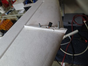
it has a large diameter CF tube that the wing tube slide into. simply slide it on and the electrical connections are made and a clip holds it all in place.

wpid-20140418_132850.jpg


I also have installed in this model another upgrade. G10 plywood replacement. It will help the techpod take much more abuse on hard landings.

 20140124_195712

Read more…
3D Robotics

3689591422?profile=originalFrom AP/ABC News:

The bald eagle, the yellow warbler and the peregrine falcon have been joined in the skies above Yosemite National Park by a noisy newcomer: the drone.

The National Park Service issued a statement Friday reminding visitors that federal regulations actually ban the use of unmanned aircraft within the park's boundaries.

Yet that hasn't stopped drone sightings from becoming a nearly daily occurrence in one of the nation's most venerated national parks in recent years, said Scott Gediman, a park ranger for nearly two decades.

"There has been an increasing use of the drones just because they are more prevalent on the market," he said, adding, "It's a new toy."

The drones can often be seen buzzing loudly near waterfalls, above meadows or over treetops as guests use them to capture otherwise impossible-to-get photographs of the breathtaking landscape.

"Most if not all of the people using these are simply unaware that they're illegal," Gediman told The Associated Press.

One problem with the devices is that they can be distracting for personnel during emergency rescue operations, according to the Park Service.

Another issue is that they make lots of noise, putting a potential damper on the park experience for visitors.

"It takes away from the soundscape and the beauty of the park," Gediman said.

The remote-operated aircraft can also interfere with sensitive wildlife, such as peregrine falcons, which nest on cliff walls.

As rangers gear up for an increase in visitors during the summer, Gediman said he hopes Friday's announcement — along with similar advisories on Facebook and Twitter — will encourage people to leave their drones at home.

Read more…
3D Robotics

From Hackaday:

We all know the scene, Obi-Wan Kenobi gives Luke a helmet with the blast shield down. He tells Luke “Your eyes can deceive you. Don’t trust them. Stretch out with your feelings!” Easy for Obi-Wan to say – he doesn’t have a remote training droid flying around and shooting at him. [Roeland] and his team are working to create a real-life version of the training droid for Hackday’s Sci-Fi contest.

The training droid in Star Wars may not have had the Force on its side, but it was pretty darn agile in the air. To replicate this, the team started with a standard Walkera Ladybird micro quadcopter. It would have been simple to have a human controlling the drone-turned-droid, but [Roeland and co] wanted a fully computer controlled system. The Ladybird can carry a small payload, but it just doesn’t have the power to lift a computer and sensor suite. The team took a note from the GRASP Lab and used an external computer with a camera to control their droid.

Rather than the expensive motion capture system used by the big labs, the team used a pair of Wii Remote controllers for stereo vision. A small IR LED mounted atop the droid made it visible to the Wii Remotes’ cameras. A laptop was employed to calculate the current position of the droid. With the current and desired positions known, the laptop calculated and sent commands to an Arduino, which then translated them for the droid’s controller.

Read more…
Developer

Something for the weekend ;)3689590893?profile=original

For many, unmanned drones are still most strongly associated with the military. Or publicity stunts by Amazon. But as the small, silent flying machines become increasingly available on the commercial market, amateur and professional filmmakers are adopting them to create footage that would previously have been impossible without a big budget and a helicopter. With the potential to produce mesmerising bird's-eye-view films – usually by attaching a GoPro camera to the device – drones are making it possible to see the world from new angles.

Last week filmmaker Honey Worth posted a dreamy video of east London filmed using a quadcopter, which quickly picked up more than 50,000 views, while earlier this month Randy Scott Slavin released a equally popular film of New York City, in which he flies a drone through the Washington Square Arch. These are just the latest additions to a growing number gravity defying new films.

So whether it’s an aerial shot of surfers riding giant waves off the coast of Oahu, Hawaii, an eerie journey through ice caves in Alaska, or a dreamlike flight through your favourite city, we’ve rounded up six of the best videos filmed by drones around the world.

From the Guardian, head on over to their site to see some great 'drone videos'

http://www.theguardian.com/travel/2014/apr/30/six-best-travel-videos-filmed-using-drones

Read more…
100KM

Techwing: an openFoam case study

Hey everyone!

 I am really getting a handle on openFoam. I have figured out the scale and mesh resolution problems I have been having. I can now produce highly detailed data sets of the air flowing over the current techwing design.

tip-vortex.jpg?w=900

this is the airflow over the wing tip. Needs improvement. 

tip-vortex3.jpg?w=900

here is another look from the side the surface is colored with the local pressure numbers. red is highest blue is lowest

negative_p_points.jpg?w=900

This is a view showing the negative pressure contours, represented by colored points.

pillowofair.jpg?w=900This shows the positive pressure contours. 

Now I can make some minor changes to the geometry and see exactly how it will effect performance and flyabilty. Check hobbyuav.com for the latest techwing news.

Read more…

NAVIO: high rate IMU on Raspberry Pi

Hey guys!

We made a small demo of IMU with NAVIO to show real-time performance of the platform.  The algorithm is Mahony quaternion based. The sensor is MPU9150 connected over I2C.

The IMU runs well over thousand of Hertz and takes around 20 percent of CPU. When running on typical for autopilots 200Hz update rate the load falls down to 4-5%, and when pumped up to 3000Hz takes almost 50%.

Raspberry Pi is able to perform other tasks while running an IMU, in the video we demonstrate that such heavy tasks as compilation do not affect the rate of the real-time IMU.

Also, there’s a PWM controller working simultaneously on the same bus, which can be seen by the LED changing colors.

In the final version of Navio we are using MPU9250 that is connected over SPI and can be polled at the full gyro update rate. 

For more information about the project please visit our blog at emlid.com

Read more…

Open Source FPV Project - OpenFPV

3689591318?profile=original

I started an open source project to make FPV with the raspberry pi easy to use for every one and wanna invite developers to join. At the moment it is not available for download.

Current Features:

  • Recording
  • Web interface
  • Low-Latency H264 Streaming (≈120ms)
  • RESTful API
  • Customizable
  • Extendable
  • Installer (in progress)
  • Minimal bettery consumption

Roadmap:

  • Invite more people to join the development team
  • Complete the installer
  • More field tests with different setups
  • Create desktop applications for mac/win with HUD support
  • Add OculusVR support

If you are interested in the project please let me know, if you want to contribute to the project please contact me: contact@openfpv.org

The project website is http://openfpv.org

I will post updates about the project status in the future.

How the system embedded control panel looks like in the moment:

3689591295?profile=original

Thanks to every one who providing blog posts around this topic, especially

Philip from diydrones.com with his great article: http://diydrones.com/xn/detail/705844%3ABlogPost%3A1433488

who gave me the initial input to start it. Philip I invite you to join OpenFPV.

Read more…

3689591209?profile=original

Hi all,

Some months ago I decided what new camera I will use for my big Hexa. Many many people are using Sony NEX5 cameras for aerial photography. However they a expensive and you need IR Trigger electronics.

I took a look at Samsung NX line and found Jeff Taylor (thanks for the inspiring post) post about triggering them with a simple resistor (not said in that post but I guess you need relays anyway). So I went for it.

I bought a Samsung NX2000 which I must say takes wonderful photos and videos. But Jeff's trigger mechanism did not work in these particular camera. After some trial-error I found that the camera "wants" you to always "focus" before trigger the shutter! No matter the camera setting,  believe me!

So what I have. I have an Autopilot that (in relay mode) outputs 5V(APM) or 3.3V(Pixhawk) for a given period of time (shutter time).

With that signal I have to use relays to create two shorts in NX2000 USB pins. One short between FOCUS pin and GND pin and another short between SHUTTER pin and GND pin.

3689591165?profile=original

Samsung NX2000 is quite restrictive in how to short those pins. After more trial - error I discovered the following:

  • SHUTTER and FOCUS pins cannot be permanently connected one each other. Otherwise, no shutter
  • FOCUS has to be shorted to GND some "time" before SHUTTER does. If you short both of them at the same time to GND, you will have a random behaviour. Sometimes it works and sometimes not. This was really annoying as it prevent you to use a double relay to short both pins at the same time

So I decided to built a small circuit to trigger the camera by shorting FOCUS to GND and then (anytime after) SHUTTER to GND

I used what I found at my local electronics store. It maybe done differently!

The circuit for triggering NX2000 receives 5V Vcc, 5V signal (will trigger relays, etc) and GND either from APM or from a 5Vto3.3v level shifter if we use Pixhawk.

Bill of materials:

 - 1x NE555

 - 1x 1uF capacitor

 - 1x 18k resistor

 - 1x 10nF capacitor

 - 2x double micro relay

3689591230?profile=original

The mechanism is as follows. Once the signal goes high (5V), it drives the relay ON. This relay has two lines, the first shorts FOCUS and GND. The second allows 5V vcc to go and feed the NE555 timer.

So we have already provided focus to the camera. Now we only have to trigger the shutter.The amount of time that the NE555 takes to boot up is going to be our FOCUS-SHUTTER delay. It is normally 100ns.

Once the NE555 boot up it always sees a short in it input pin. Therefore it puts its output high what drives the second relay.

Once the second relay is activated, a short is created between SHUTTER and GND.

On this point you should have a nice picture taken in the NX2000!!

One thing left to say. If you come from Pixhwak world you need to convert 3.3v signal to 5V.

I used Marco's circuit in this post. 

3689591179?profile=original

As you can see all three boards/circuits are connectable/stackable one each other.

Here you can see the full picture:

3689591244?profile=original

The FOCUS-SHUTTER delay may have been done with a RC net but I chose NE555 in case a needed to control delay accurately. However I would have needed another NE555....... 

For Pixhawk connection I connected it to OUT 5 (as 1 to 4 are configured PWM) and Relay mode. 

3689591190?profile=original

3689591308?profile=original

Some pictures of the process and final result

Bench test:

3689591270?profile=original

USB Connector

uc?export=download&id=0BzRzbaLTcOpbWFhmUGxVVkx4UzQ&width=750

Everything in a prototype pcb

uc?export=download&id=0BzRzbaLTcOpbT2xma1phREpqcTA&width=750

Already mounted on gimbal with shrinking tube

uc?export=download&id=0BzRzbaLTcOpbbU5BLWVuLTRYSUE&width=750

Read more…
MR60

I found this article which is quite a demonstration by the absurd of how when a technology (micro UAVs in this case) is beneficial to the industrial-military industry, it will get through any FAA or any other regulations. Another sign we're really under large corporations' governance.

So, in other words : develop a potentially very dangerous (privacy, invasive, weaponized, etc) application of UAV tech, and you will get a green light to do whatever you want with it even in the middle of the US; However you'd like to fly your harmless quad that carries a gopro  : that's a no no - you can't fly it - forbidden - bad bad bad - too dangerous.

This would laughable if it wasn't so absurd: try to make citizens believe your IRIS or AR drone is dangerous for the sake of privacy protection (and all other arguments we hear from FAA against UAVs civilian uses), but then it's ok to spy on your citizens - everyone being a potential terrorist - do not forget that,  (and on other countries of course, preferably US allies).

Hereunder the text accompanying this YouTube video: (I do not support necessarily views & opinions expressed in this relayed text. Everyone is free to think for himself and should think for himself with a critical mind!)

Air Force Bugbots Nano Drone video gives a peak inside what nano-drone technology the Federal Government is currently implementing within the united states more than a scary thought or sci-fi movie, they have arrived.

The deadly, insect-sized drones of the future - Unobtrusive, Invasive, and Lethal are here as depicted in this old video

The Air Force is reportedly developing winged drones that can sneak up on a suspected enemy as stealthily as a mosquito

This is the video missing from this article:
http://theweek.com/article/index/2402...

A law signed by President Barack Obama in February 2012 directs the Federal Aviation Administration (FAA) to throw American airspace wide open to drones by September 30, 2015.

Nano sized Drones Combined With DNA Hacking Could Create A Very Scary Future for the United States in light of a law president Obama signed last year implementing a fleet of at least 30,000 spy drones to spy on small town USA no later than 2015 to spy on Americans.

Unfortunately this is a true story and as long as we continue to let politicians like President Barack Obama and other democrats pick apart and fundamentally change our constitution instead of protecting it, we move closer to an extreme communist state in our country.

In case you didn't know it - and you probably didn't - Congress, with little fanfare, passed an FAA re-authorization bill that President Obama signed into law that will put 30,000 flying drones spying on Americans across U.S. cities by government.

People are already nervous about the prospect of being watched by law enforcement (and possibly the military or DHS), but our leaders employ these tools nevertheless and "we the people" are letting them.

Even the liberal news huffington post has a video news story about this although they try to legitimize the reasons for needing this to save lives.
http://www.huffingtonpost.com/2012/09...

The president has ordered 30,000 spy drones to be used within the United States to spy on Americans to be implemented by 2015
We are already seeing evidence of spy drones being used within the United States and NOT for border patrol

Government Spy Drone Crashes in Maryland but what about preserving our constitutional rights and freedoms?
http://baltimore.cbslocal.com/2012/06...

MORE SOURCES AND RELATED STORIES:
The Future of Drone Surveillance: Swarms of Cyborg Insect Drones -
http://www.networkworld.com/community...

Tiny robot mosquito drones being researched by the US government -
http://2tfu.com/2012/06/16/tiny-robot...

National Geographic Story:
http://ngm.nationalgeographic.com/201...

Government Working On Mosquito-Sized Drones - http://www.ijreview.com/2012/06/8545-...

Micro-Drones Combined With DNA Hacking Could Create A Very Scary Future - Business Insider - http://www.businessinsider.com/govern...

USA Today Story: http://usatoday30.usatoday.com/news/w...

Studying butterfly flight to help build bug-size flying robots -
http://phys.org/news/2012-02-butterfl...

US military developing insect surveillance drones - http://www.presstv.ir/detail/2012/07/...

Video of squadron of nano quad rotor aerial drones -
https://www.youtube.com/watch?v=YQIMGV...
http://www.huffingtonpost.com/2012/02...
http://www.theblaze.com/stories/2012/...

British Army Using Tiny Drones:
https://www.youtube.com/watch?v=d5TdbM...

Drones In U.S.: More Unmanned Aircraft Will Be Flying In Domestic Airspace By 2015 (VIDEO) - http://www.huffingtonpost.com/2012/09...

Washington Times Story over Domesticly Used Drones: http://www.washingtontimes.com/news/2...

Snopes reports nano drones true but then brushes it off - http://www.snopes.com/photos/technolo...

Read more…
3D Robotics

3689591143?profile=original

[UPDATE: We now sell a Bluetooth set that has all this pre-setup for you. If you get that, no need to read further!]. We're going to be adding Bluetooth connectivity to more 3DR products in the coming months, but there's no need to wait. Right now you can add Bluetooth connectivity yourself with cheap third-party bluetooth modules. Connecting the APM and Pixhawk via Bluetooth is a great way to do basic setup and mission planning with your laptop (Mac, PC or Linux) or Android phone or tablet, without the need to carry and connect a 3DR radio and OTG cable.  You’re limited to Bluetooth range (about 50m), but for wireless setup before launch, this works fine.  Mission Planner (Windows), APM Planner (Mac, Windows, Linux), DroidPlanner and AndroPilot (both Android) all support Bluetooth connectivity.


This tutorial will show you how to connect two kinds of commonly available Bluetooth modules (shown above) to APM or Pixhawk.

The process consists of three steps: 

  1. Configuring the modules so they’re running at 57600 baud
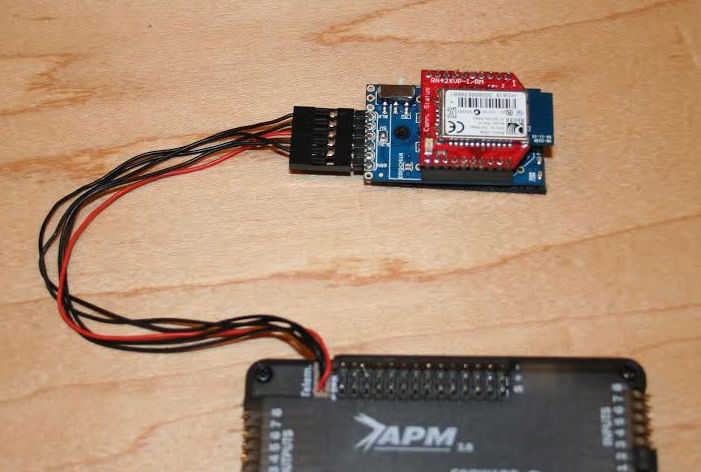
  2. Physically connecting the modules to APM/Pixhawk
  3. Connect via BT to your Android device or laptop and a GCS app (pair the module with your device)


Option 1: Setup with RN-42 and RN-41 Bluetooth modules


Connect the module with an XtreamBee adapter board and this cable

g_B8E93AMguxqCeHDMKVpJcHzH9edrF6ttUQ_EIRshx_Y2R1fOeK3BmhOnozob6gDAaJkwAPxhxj8jTvXrPg5nI6V2mhXvl6qftfwzJZoSYurmZJJZxYU_8gBFm-lBMv6A


TO GET THE COMMAND PROMPT


You can use any serial terminal program (the terminal in the Arduino IDE is shown), but there are a few things you need to do:

  1. You must enter command mode within 60 seconds of powering up the board
  2. The board can’t be already wirelessly paired with a device (such as your phone or tablet)
  3. The default baud rate is usually 115200. We need to change that to 57600 baud. But for the first connection, to get the command prompt for this change, we’re going to start at 115200.
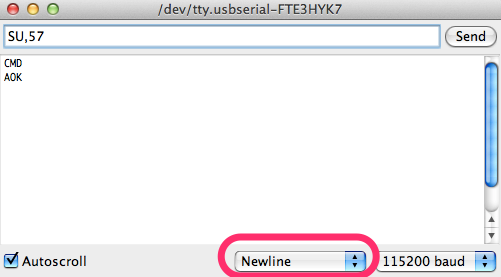
  4. To get to command mode, you need to select “No line ending” in your terminal program, then enter “$$$” [enter]. After that, the terminal program needs to be in “Newline”  mode, as shown below. Crazy, but that’s the way Roving Networks set it up. Now you know!

First, ensure that your terminal baud rate is at 115200 and “No line endings” is selected. Then plug in your module and within 30 seconds type “$$$” [enter]. You should get the return message “CMD”.

3689591252?profile=original

Once you have that, switch your terminal program to “Newline” for the rest of the commands.

_dev_tty_usbserial-FTE3HYK7.png

Now you can enter commands. To switch to a 57600k baud rate the command would be "SU,57" (A full list of commands is here, although you won’t need them for this change). Once you reboot the board, that baud change will take effect.


Congrats, you’re done! Now you’re ready to use it with APM/Pixhawk. See the bottom of the post for instructions on how to use the GCS apps with Bluetooth.


-------------------------


Option 2: Setup with cheap ($10) HC-05 Arduino Bluetooth Module


Full instructions are here, but the basics are below:

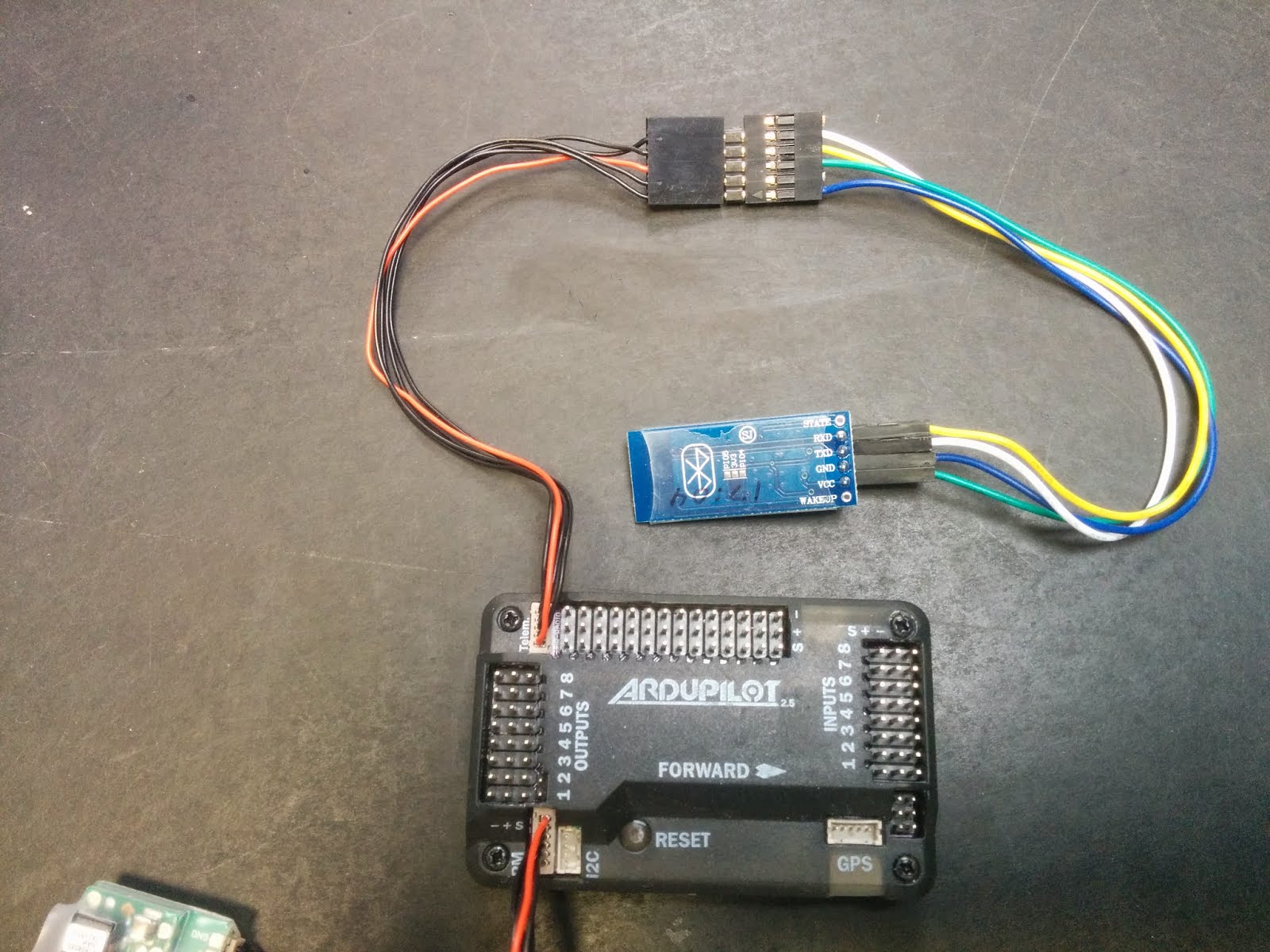
IMG_20140423_113806.jpg

 You can make your own cable by swapping some wires in the standard 3DR telem-to-Xbee adapter cable. For clarity’s sake, I’ve used some color-coded wires above to show what goes where.


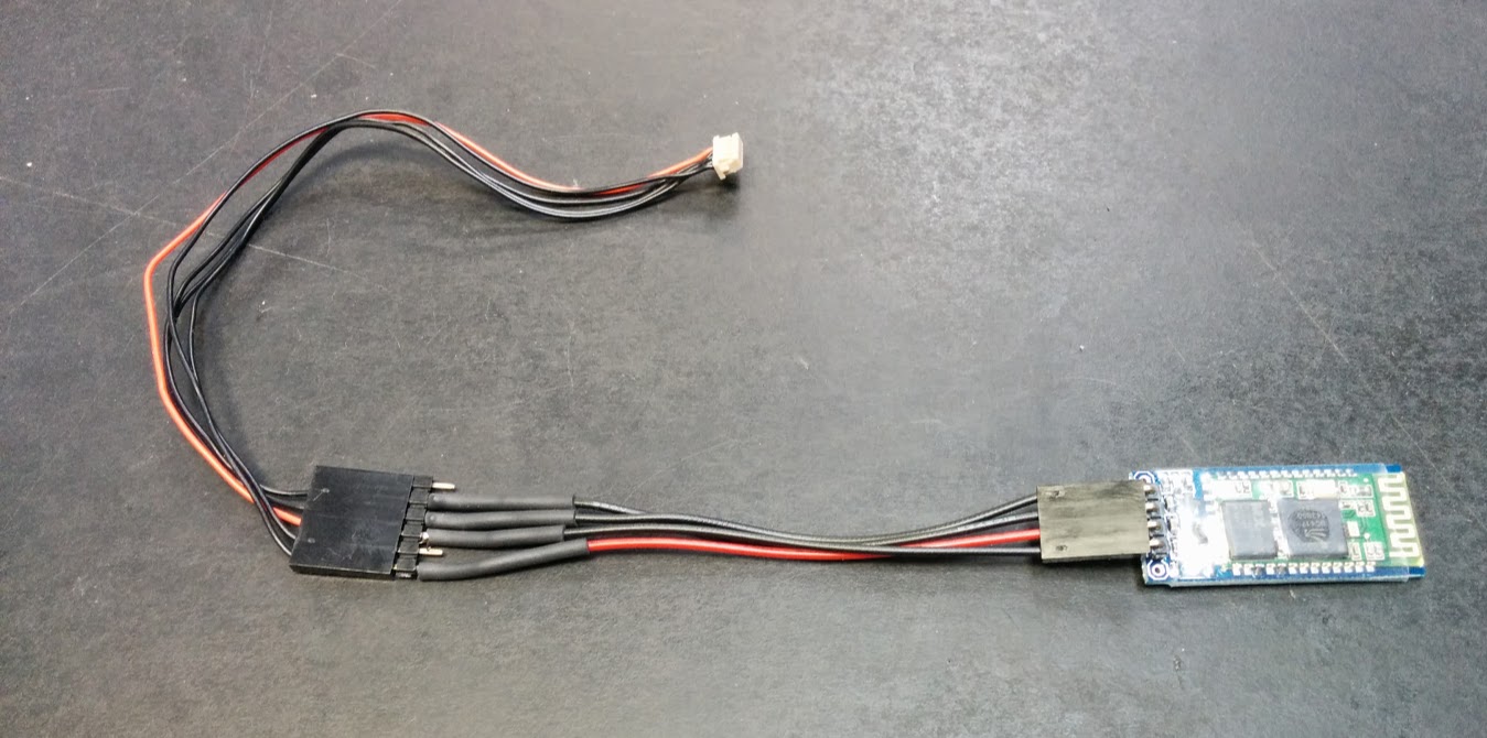
Here’s a neater cable that I’ve made with some regular breakaway header pins:

IMG_20140501_102034.jpg


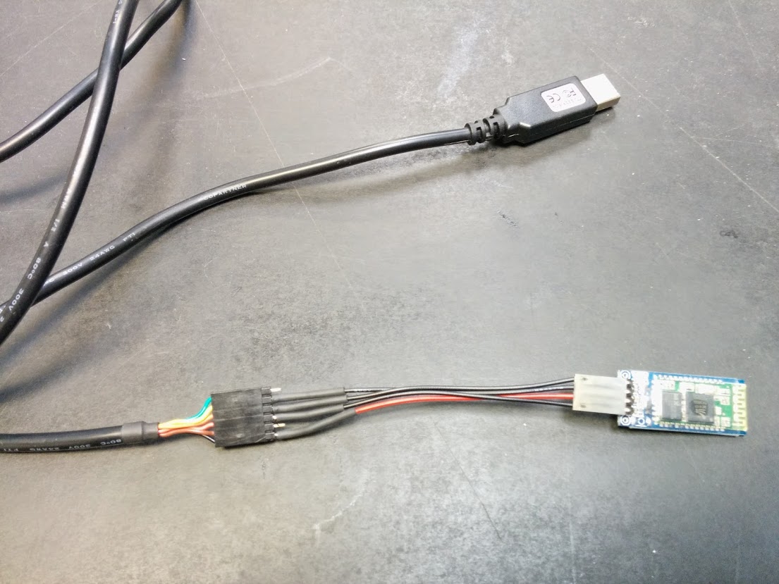
This same custom cable will allow you to plug it into a regular FTDI cable (shown below) so you can change the configuration of the Bluetooth board to switch the default baud rate from 9600 baud to 57600 baud.

IMG_20140501_102142.jpg

Once you’ve plugged the board into your FTDI cable and plugged that into your computer, it will show up in your computer as a serial port. The LED on the board should be blinking red, not blue. You should NOT wirelessly pair the Bluetooth model with any device at this point; if it the LED is blue that means that it’s paired with something, so if that’s the case make sure that you unpair it first.  At that point you can use any serial terminal to communicate with the Bluetooth module. For the sake of this demo, we’ll use the serial terminal built into Arduino.


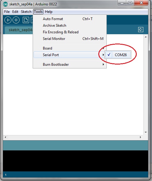
First, select the port assigned to your FTDI cable (it probably won’t be 26, as shown below, and on a Mac it may show us as “tty-usbserial”):

ConfirmCOMport.jpg

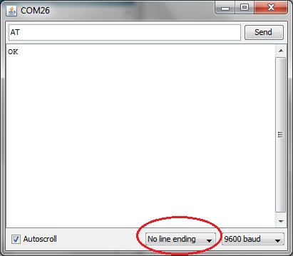
Ensure that the serial terminal baud rate is set for 9600 baud and “No line ending”, as shown.


Type AT [return]. The board should return “OK”.  That means that all is well and you’re talking to the board. If you don’t get a return, check your wiring and make sure that the Bluetooth board is showing a blinking red LED (powered on) and is not blue (paired with something).  

AT-OK.jpg


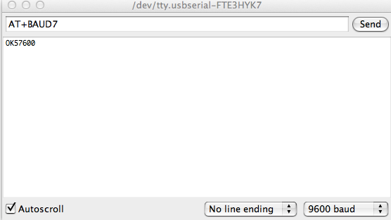
Now we can change the baud rate to 57600. The command for that is “AT+BAUD7 [return]”, as shown. If this is a success, it will report back “OK57600”, as shown below. If so, you’re done! Unplug the board and you’re ready to use it with APM/Pixhawk.

_dev_tty_usbserial-FTE3HYK7_and_Bluetooth_module_configurations___www_hobbyist_co_nz.png

-------------------

Now that you have your module working, you just need to pair with your device. On Android, this is the Bluetooth settings. Set your device to "discoverable" and you'll see the module show up. Then pair it. If it asks for a code, type "1234". 

Once it's paired you can connect with either Android app: DroidPlanner 2 and Andropilot. On Andropilot, there's a button marked "Bluetooth" on the main screen. On DroidPlanner, go to the settings menu (top left) and under "Telemetry Connection Type" select Bluetooth and the module you've paired with it. 

Both of these modules work great with either app!

DroidPlanner_2_-_Android_Apps_on_Google_Play.pngAndropilot_-_Android_Apps_on_Google_Play.png


Read more…

3689591070?profile=original

For anybody interested in using a joystick or flight yoke to pilot your ArduPlane, I have successfully configured the CH-Products 'Flight Yoke' to work with a Spektrum DX6i using a PPM converter and a script written for the yoke that will allow you to change flight modes from the yoke using the buttons and the programming language supplied with the yoke driver.

The yoke can be purchased from here

I paid $85 for one and it works great. There is a newer model, but for basic flying, this one has plenty of buttons and knobs to get the job done.

The PPM converter that I used can be purchased here

This is the 'CompuFly' ppm converter for use with JR transmitters, but it also works with the Spektrum DX6i (and I assume other Spektrum transmitters), by flipping the polarity to 'positive' PPM.

Part 1: Configuring the Flight Yoke:

The main screen of the flight yoke software panel looks like this:

3689591070?profile=original
You should test the joystick with your flight simulator before you try making it work with the PPM converter. My test was done using X-plane. It's as simple as following the wizard, and proceed to the 'Test/Calibrate' screen to get the yoke setup for normal windows joystick operation.

Once you have added your yoke to the CH Control Manager, you can then proceed to configure each axis to control your plane. My setup has the following configuration:

Joystick X-Axis (A1) =  Roll 

Joystick Y-Axis (A2) = Pitch 

Joystick Z-Axis (A3) = Throttle

Joystick U-Axis (A4) = Yaw

Joystick Slider-0 = Gear channel (Button 5 and 6) 

Joystick R-Axis = Button modes:

Button 9 = FBWA mode

Button 10 = AUTO mode

Button 11 = RTL mode

Button 12 = MANUAL mode

The modes are (of course) going to be whatever you have them set to in your ArduPilot, but these are the ones I have in my default config. The resolution of the modes can also be modified and more buttons added to the script to achieve more mode possibilities, but my DX6i is setup for 4 modes. 

For the Yaw axis, there is no actual joystick input because I do not have the pedals, so I chose to use a mixing mode and added the Roll channel to the U-axis output in a script to simulate the rudder working with the roll channel. The rudder mixing will apply when flying in MANUAL mode. The ideal simulator would also have the pedals which are optional. You can buy these as an add-on and use them with the yoke and create a single simulated joystick.

I will describe how to setup the script to achieve the rudder mix and button mode code to make this setup work with the ArduPilot for those that do not have the pedals. 

To customize the output of the yoke, the yoke must be configured to run in 'mapped' mode as shown in the following screen:

3689591108?profile=original

The "CMS Controls" tab will allow you to select which joystick channel will be used in the scripts and which joystick output will be assigned to that channel. 

My configuration is as follows:

CMS.A3 = R Axis (Button Modes)

CMS.A4 = U-Axis (Yaw Channel) The output is computed in the script. 

CMS.A5= Slider-0 (Gear Channel on radio)

To make these channels programmable, check the "DX Mode" box as shown above.

My transmitter is a 6 channel device, however if yours has more, you can just pick additional CMS inputs to use for the other transmitter channels, and assign them accordingly

On the "FS Yoke" tab, the first three channels should be assigned to Roll (X-Axis), Pitch (Y-Axis), and Throttle (Z-Axis) respectively, and the 'DX Mode" box checked for these channels. This will force the yoke to pass these channels through to your transmitter without any software input. If you want to modify the behavior of these channels in the script, then you must uncheck this box on the 'FS Yoke' tab, and check the box on the CMS Controls' tab for that axis. 

Creating the Script:

The script is actually very simple. For the rudder mix, it's one line of code:

 CMS.A4 = JS1.A1/4+32;

This will give you a 25% rudder movement compared to the roll when flying in MANUAL mode. You can play with the mix as you desire. If you are flying in FBWA, you probably have some rudder mix, so it's probably a good idea to match that here. If you don't want any rudder mix, delete this line of code and the rudder will stay fixed in MANUAL mode.  For stunt flying or 'knife edge' tricks, you may want to get the pedals, or try assigning the 'prop' or 'fuel mix' channel to the rudder and use the slider to control the rudder - this is advanced, and I have not attempted such a configuration but it's possible to setup using the scripts.

Here is the entire script:

// CMS Script File
//
// Game Title:
// Written By:
// Date:
//
script

CMS.A4 = JS1.A1/4+32;

IF (JS1.B9) THEN
CMS.A3 = 0;
ENDIF

IF (JS1.B10) THEN
CMS.A3 = 110;
ENDIF

IF (JS1.B11) THEN
CMS.A3 = 190;
ENDIF

IF (JS1.B12) THEN
CMS.A3 = 255;
ENDIF

IF (JS1.B5) THEN
CMS.A5 = 0;
ENDIF

IF (JS1.B6) THEN
CMS.A5 = 255;
ENDIF

endScript

To cut and paste the script into the joystick, press the "CM Editor' button on the toolbar and paste it in. Then press the "Download" button as shown in this screenshot:

3689591081?profile=original

Once you have 'downloaded' the configuration, you can then test it. You should see the following screen after you enter the test mode:

3689590988?profile=original

Moving the yoke and observe the channel outputs.  "Roll" should move the X and the U channels. The U channel is the rudder mix. The "Pitch" should move the Y-channel, and Throttle should move the Z channel. 

The R-channel should be changing when you press the buttons that you have configured to control the modes. On my configuration, buttons 9 -12 control the modes.

Lastly, buttons 5 and 6 should control the S0 (Slider 0, Gear channel). On my plane, this turns on the camera for FPV.

Part 2: Configuring the PPM converter

The CompuFly USB PPM converter has a single screen configuration as shown as follows:

3689591131?profile=original

For the Spektrum DX6i, set the modulation to 'Positive PPM', and 6 channels. If you have a different radio, you will have to check the documentation or experiment. For my radio, I have channels 1-4 set to INVERT, (inv check box). These are the surface and throttle control channels. You will need to experiment to get these right for your plane and transmitter depending on how your servos are configure with the ArduPilot. For the 'flight modes' and 'Gear' channels, my configuration is set to non-inverted.

The key point of the configuration not shown here is the Joystick-to-channel mapping which is in the (settings.ini) INI file stored in the same directory as the CompuFly.exe application.

Here is my configuration:

[SETTINGS]
PORT=COM23
ChannelCount=5
PPMType=1
Compufly2=1


[INVERT]
CHANNEL1=1
CHANNEL2=1
CHANNEL3=1
CHANNEL4=1
CHANNEL5=0
CHANNEL6=0
CHANNEL7=0


[TRIM]
CHANNEL1=0
CHANNEL2=0
CHANNEL3=0
CHANNEL4=0
CHANNEL5=0
CHANNEL6=0
CHANNEL7=0


[EPA]
CHANNEL1=100
CHANNEL2=100
CHANNEL3=100
CHANNEL4=100
CHANNEL5=100
CHANNEL6=100
CHANNEL7=100


[CHANNELS]
CHANNEL1=3
CHANNEL2=1
CHANNEL3=2
CHANNEL4=5
CHANNEL5=7
CHANNEL6=6
CHANNEL7=10

#Channel Axis Numbers
# X axis = 1
# Y axis = 2
# X axis = 3
# RX axis = 4
# RY axis = 5
# RZ axis = 6
# S1 axis = 7
# S2 axis = 8
# HTX axis = 10
# HTY axis = 11
# SWC axis = 12


You can cut-and-paste the previous text directly into your INI file. Take care to test this completely with your plane on the ground and the prop removed! If you get the throttle channel backwards, the motor could go full on you. Be careful here.

To test your setup, plug in the PPM converter to the back of your transmitter in the 'Trainer' port, and turn on your transmitter and power up your plane. Flip the 'trainer' switch on the DX6i.  Move things around and see what happens! For my transmitter, I replaced the trainer switch with a more robust toggle switch. The original one broke off. 

If everything is good, you should be able to control everything using the Flight Yoke, including the flight modes. 

Happy Flying!

Read more…
300km

Anatomy of a 301 km Flight

3689591030?profile=original
Today I flew my Cyclops EPO for an incredible 7 hours and 8 minutes, covering 301 km (301 km !!!) in one flight.


After flying my Maja for 126km I decided 200km would be my next challenge. I got the Cyclops with that in mind, it was very very efficient straight out of the box and after my first flight test I realised it was capable of much more.


I did 5 flight testing sessions where I tested different speeds, C of G positions and propellers. The data from my last two sessions suggested 300km was possible with good conditions so that became my goal.


I planned my mission with a couple of waypoint path options that I could switch between using do_jump. After a hand launch I switched to auto for a very gentle climb reaching 50m of altitude over about 2km. I flew a few laps of a 2.5km lap, before switching to a 3km lap and then a 3.5km one which used a do_jump command to fly continuous laps at 60m altitude.


To monitor my progress I’d made battery consumption schedules for 250, 280 and 300 km. My calculations said that I would need to run my batteries down to 10% remaining to reach 300 km. The first half of the flight was very calm and I was ahead of schedule. But the wind picked up in the afternoon and it became apparent that I might finish with less than 10%. I tried to help the situation in the last hour by varying my speed around the lap. I flew at 14 m/s for the head and cross wind sections, and dropped to 13 m/s when I had a tail wind. I hadn't done any calculations to support that, it just seemed that I could make the most of the tailwind section by dropping my power there a little.


I’d decided in advance to end the flight when the battery dropped to 12 V (3.0 V per cell) and I could see as I passed the 280 km and 290 km milestones that it really was going to be tight. The voltage was hovering either side of 12 V as I approached the 300 km mark so I knew it was time to bring it in, but I also knew that Mission Planner can underestimate the distance compared to the GPS log. I decided to fly to 303 km to be safe. The way the laps worked out it was 305 km when I hit the ground, and just as well because the GPS log came up as 301 km. If I’d come in when Mission Planner told me 303 I would have been member of the 299 club.

3689591045?profile=original

The telemetry log file is 47 MB (linked below) and Mission Planner crashed when I tried to create the KML file (I tried on three different machines). It did manage the GPX file thankfully.
Key specs:

  • Cyclops E with V-tail
  • APM 2.5
  • Panasonic 18650B Li Ion batteries. 4S7P, 23,800 mAh
  • Aeronaut 11x9 prop
  • Hobbyking telemetry
  • Distance covered: 301km (according to GPS log file, 305 km according to Mission Planner)
  • Flight duration: 7 hr 8 min 10 sec
  • Average groundspeed 41.7 km/hr

Log File (47MB)

Read more…