I have designed a couple of 3D printed accessories and would like to share them with the community.
This for a Talon design to raise the electronics of the ground.
Magnetometer stilt to raise the external module.
Here is the STL files
I have designed a couple of 3D printed accessories and would like to share them with the community.
This for a Talon design to raise the electronics of the ground.
Magnetometer stilt to raise the external module.
Here is the STL files
From Gizmag:
The swiftlet may not look much different than other little birds, but it has one unique ability – it builds its nest out of its own saliva. Inspired by the swiftlet, scientists at Imperial College London's Aerial Robotics Lab have created a robotic quadcopter that can extrude polyurethane foam while in flight. By targeting where that foam goes, it can build up simple structures, essentially becoming a flying 3D printer. The technology could have some very important applications.
Developed mainly by Graham Hunt and other members of a team led by Dr. Mirko Kovac, the robot's platform is made from inexpensive 3D-printed components and carbon fiber supports. It has two canisters containing separate liquid chemicals on its underside. When those chemicals mix together as they pass through its extrusion nozzle, a chemical reaction occurs and they turn to foam.
In its current form, the aircraft uses GPS and an external system of 16 infrared cameras to identify targets upon which to spray the foam, within an indoor lab. That sensor data is transmitted to a nearby laptop computer, that is able to compensate for the constantly-changing angle and mass of the copter's printing payload. Based on that processed data, the computer relays flight and extrusion commands back to the robot.
Down the road, however, Kovac's team hopes to create fully-autonomous UAVs equipped with their own high-speed cameras and 3D depth senors, that could function in a variety of chaotic, real-world conditions.
At that point, they could conceivably be used for applications such as performing repairs in areas too remote or dangerous for humans to easily access, such as wind turbines or nuclear reactors. They could also pick up and remove hazardous items such as bombs or radioactive waste – which is where the team's second robot comes into play.
It's a hexacopter, and instead of an extrusion system, it just has a disposable flat surface on its underside. After the first robot (the quadcopter) sprays foam onto a target, the hexacopter simply lands on that target, waits for the wet foam to cure onto its underside, then flies away with the target adhered to it.
Kovac ultimately envisions a whole bio-inspired system, in which swarms of such "wild robots" will autonomously build platforms that they could use as a base of operations, and where they could also recharge their fuel cells via built-in solar cells.
"Like in nature, the robots will have specialized functions and division of labor," he explains. "Using swarm intelligence, the robots will be able to perform very complex tasks of autonomous inspection and aerial construction effectively. For example, inspection drones will create a 3D scan to detect damage in hazardous environments and a second swarm of construction drones will selectively repair the structure with aerial 3D printing."
The quadcopter robot will be on display this weekend at the college's Imperial Festival, while a paper on the research will be presented later this month at the International Conference on Robotics and Automation, in Hong Kong.
Source: Imperial College London via New Scientist
Dear Friends,
today we finish to test first prototype of micro brain , this is the video of first power on , all work fine , we check all onboard sensor : IMU , BAROMETER . Check eeprom for parameter storage and SD card. Serial port , and usb interface . All work fine :) Check also new bootloader and our mission planner fork with VRBrain support all work perfect . Diego our Electronic Designer doing a great work no error until now :)
Today 09/05/14 finish the test of all subsystem : Magnetomer , GPS , RC IN PPMSUM and RC OUT and all work fine . See the video .
These are the specification :
CPU STM32F4 VR OS based on NuttX kernel 7.1
1 EEPROM or FRAM device for parameter storage.
IMU MPU6000 SPI.
MSIC Barometer 10 cm resolution.
8 PPM Radio RC Input .
8 PWM ESC - SERVO Output.
1 SBUS Radio Input compatible with Futaba SBUS and Spektrum ,too
1 SBUS Servo Output.
SD Card Reader until 64 Gbyte.
1 RGB LED
2 LED Output
1 Buzzer Output
On board telemetry module availabe at 433 / 868 mhz. (option)
connector for external 3DR/VR GPS + MAGNETOMETER
dimension : 3.2 x 3.2 .
weight : 10 gr
Price is 99 euro the board pre order is open the mass production start in 1 week when finish the test of first production batch .
more info about status of the product on the store: http://www.virtualrobotix.it/index.php/en/shop/autopilot/vrbrainmicro51-detail
APM Copter , Plane , Rover Firmware available and fully tested by our devteam.
official blog post : http://www.virtualrobotix.com/profiles/blogs/vr-micro-brain-5-1-is-alive-first-power-up-and-os-check-up-fantas
for more info send a mail to info@virtualrobotix.com
Best
Roberto
Simple Modular Flight Mode Switch - Build it for $20

So... after reading Max Levine's Blog here about a simple 6-Way Flight Mode Switch, I decided to make my own; but I wasn't exactly satisfied with the lack of clear mode indicators.
I've also read about jDrones Arduino Flight Mode Switch based on Stefan & Roman's work; it REALLY is an awesome bit of fabrication. But after what appears to be stalled development for the last few months, I began to have second thoughts about their design.
IMHO, breaking the entire PPM chain, running it through plug-in connections to an add-on CPU, then injecting a modified PPM signal back into the TX JUST to be able to synthesize outputs to ONE channel... that is beyond tempting fate; it is BEGGING Murphy to make an example of you in a manner suitable for a Darwin Award.
[EDIT]
After some several conversations with Stefan, I find that I was mistaken about how his Arduino-based switch works; it doesn't "loop out" the PPM stream, it only adds a PPM stream for one channel which the TX is then expected to mix to the channel being used to control the APM Mode Selection.
While I still believe in the KISS principle, and like my design better for its simplicity, I think our major disagreement really revolves around which is more intuitive to use blind; a rotary knob or pushbutton switches. This is a debate which has plagued designers of electronics since the dawn of electronics; I don't think we're going to definitively resolve it for all time over this one little project. ;)
[/EDIT]
So I decided to employ the KISS principle; keep it Analog, keep it within the grasp of ordinary tinkerers, and make it the best I can with off-the-shelf components. I wanted to be able to take it off my TX with a minumum of fuss, so it needed to be self-contained. After much consideration, I formulated a design that was very simple and adaptable which anyone with basic hobbyist fabrication skills and tools should be able to duplicate.

This was the result.
THE CIRCUIT:

Alternate Circuit with TrimPots:

PARTS LIST:
Radio Shack
$3.49 (1) Radio Shack # 270-1801 3" x 2" x 1" plastic Project Enclosure
$2.99 (1) Radio Shack # 274-0433 1" Red Insert Control Knob
$3.49 (1) Radio Shack # 275-0034 2-Pole, 6-Position Rotary Switch
OPTIONAL: $14.49 (1) Radio Shack # 271-312 Resistor Assortment (Jeez - I remember when this was $3.99, and STILL way overpriced)
Generic Parts
(1) 22Ω (Red, Red, Black) 1/8W or 1/4 W Resistor
(2) 1500Ω (Brown, Green, Red) 1/8W or 1/4 W Resistors
(3) 820Ω (Grey, Red, Brown) 1/8W or 1/4 W Resistors
These are available in the optional kit above if you don't have them in your parts bin; otherwise, there are several vendors on eBay who Sell small lots (50-100 pcs) of individual values for $1-4/lot.The pin spacing on the switch lends itself to substituting 1/4w SMD resistors, I just happened to be out of 820Ω at the moment, so used regular axial-lead resistors.
$3.29 (6) PLCC-6 5050 White 3-Chip White LEDs ( Be SURE to get 3-CHIP White LEDs to match the 22Ω ballast resistor; I bought these: www.ebay.com/itm/300939331755)
$2.00 (2) 6"-10" Servo Wire W/Female Plug
$1.00 (1) 3-Pin header or Male Servo Plug $2.00
(6) Lego Part # 362201 1x3 Brick in White (I snurched grey ones from my son's 20-ish pounds huge collection)
(1) 1" x 3" flat scrap of clear blister-pack plastic (From the top of a Cake Box or similar thickness)
(1) 1 sheet Glossy Photo Paper
Alternate Configuration:
(4) 10KΩ 1/2W 25-Turn Trimpots, Series 3296 (I bought mine here: )
Add a couple bucks for paper and incidentals and we're right around the $20 mark; plus cost of resistors if you don't have them in your parts bin. (Shame on you. ;-) )
Theory of Operation:
I wanted my design to be able to work with any TX; so I chose the simple black box, which is JUST big enough for the components we'll be using. I've designed my Mode Switch around a Left-hand side installation for certain reasons; I want to be able to use it without taking my hand off the cyclic (RH in my case) stick, and placing it on the side means I can operate it with fingers and still keep a thumb on the Yaw/Throttle stick. I chose the big red knob as an homage to Jean-Baptiste Emmanuel Zorg and his "little red button". ; -)
Due to the leverage of the large knob, one can easily operate it with fingertips; the pronounced pointer on the knob means that once one gets used to it, one can actually tell by FEEL what mode s/he's in without having to look at the display.
I've placed my STABILIZE and RTL modes at the top and bottom of the range on purpose; in time of panic, no thinking or taking your eyes off the craft is needed, all you need to know is to flip it all the way up or all the way down to be at whichever "Safety" mode you want. If the Mode Switch fails, either by shorting out or by going open/being unplugged, it will go directly to one of those two safety modes.
By choosing WHITE LEDs, I greatly simplify my design. When using colored LEDs, one must drive them at different current values to achieve similar PERCEIVED brightness; this would mean a separate ballast resistor for each indicator light. This design allows me to use a single current-limiting resistor for all indicators; color coding is done along with labeling at time of printing the Indicator Screen.
Max Levine's design used series-paired resistors to arrived at a value for R2-R5 of 850Ω; my design substitutes the closest standard resistor value, 820Ω. I've tested this array with both my Turnigy 9x and 9XR transmitters; results in MP are flawless. Obviously, if you are going to use this design on another model of radio, you may need to change these values to match your different hardware.
For Reference:
The Turnigy design uses a 5KΩ potentiometer, with +5V at the end of the scale and GND at the beginning. The +5V on the outer tab of the potentiometer is connected direct to the 7805 regulator with no ballast resistor, and the opposite outer tab is connected directly to GND. This means we can use the same +5V & GND applied to the outer tabs of the potentiometer to power our indicator LEDs; our entire setup can be operated through a single 3-wire servo cable!
If you are going to use this design on another TX, you need to make sure of the following:
1) That B+ voltage for the potentiometer has no resistor in circuit with the power source, whatever voltage it is. If there is one, you'll need to run a separate B+ to power the LED indicator circuit.
2) That GND for the potentiometer has no resistor in the circuit to main chassis GND; often if they use a ballast resistor in the B+ circuit, they often also use one in the GND circuit as well. If they do, you'll need to run a separate GND for the LED indicator circuit.
The reason this is important is this: If there is/are ballast resistors in the source voltage to the potentiometer, the current draw from the LED indicator circuit will cause a voltage drop which will affect the signal output. NOT GOOD!
3) My LED indicator circuit is designed to operate from a 5V REGULATED power source; the 7805 Regulator which feeds B+ to the potentiometer. If your TX provides a different voltage, you'll need to substitute a different value for ballast resistor R1.
These particular LEDs require a max of 60ma (3 Chips x 20ma ea); the 22Ω ballast resistor drives them at approx 55-57ma from a +5V source for maximum brightness. This means there is VERY little wiggle room for varying voltage above 5V.
This site will give you assistance calculating the correct ballast resistor: http://ledcalc.com (They also have Series and Parallel calculators available)
Your configuration is:
Supply Voltage: YOUR Measured Supply Voltage
LED Forward Voltage/Voltage Drop: 3.2-3.4V
LED Current: 60 Milliamps
THE BUILD:
First, we need to build the Lightbox. I chose 1x3 Lego Bricks because they are readily available, and I know they will fit in the smallest project enclosure Radio Shack sells. You can buy them individually from the Lego Store if you have one in your local Shopping Maul™ otherwise, they're $0.20 each from the Lego Store online. For convenience, I've snapped them into a piece of Lego "base plate"; this gives me a bit of leverage when working with them, and keeps them from flying away. As much.

These 1x3 bricks are just the right size; unfortunately, they have these little pins that get in our way. Some variants have this webbing between the pins and the sidewalls as well; it needs to be cut through to separate it...

then we place narrow pliers so they bottom out inside like so...

And squeeze, breaking one of the pins loose.

After that, we can grip the remaining pin like so, and rock back & forth until it breaks.

This gets us to a point where we can quickly remove the last bits of stubborm plastic with a burr on a Dremel...

And now the final form of our lightbox begins to emerge.

Next we have to drill holes for the LED wires to come through; I used a 1mm drill on my Dremel.

Drill one hole close to each side of the center peg as shown; do this for each of the 6 Lego bricks.

Now it's time to turn the bricks into one single assembly; if you haven't already, you really need to plug them into a piece of flat panel now to keep them flat and square. Be very careful with the Super Glue; more than a couple drops on each seam and you'll glue your lightbox to the flat panel.

Use the pickup tube from your CA Accelerant to place just a drop precisely on the seam...

Then, when the CA is cured, remove the assembly and repeat both steps on the seams on the opposite side.

Center the lightbox between the two screw stanchions as shown, then use a knife to precisely mark the location on the top edge of the sidewall...

Then use those marks to align the lightbox on the outside so you can scribe the cutout with your knife. I used modeler's clamps (Rubber-jawed plastic clothespin-looking things) to hold it in place so I could scribe the bottom edge.

Now it's time to cut. Use the thinnest cutoff wheel you have, and set the speed as slow as you can without stalling the motor. Cut slowly and carefully; patience here pays off in a nice-looking end product. If you go too fast, the cutting action turns to friction/heat/melting action, and you'll distort the plastic and get bits of melted plastic everywhere. If your hands are steady enough, they do make sawblades for the Dremel; I find that the sanding action of the cutoff wheels makes a much smoother edge with my not-so-steady hand.

Here's the rough cutout; you are going to cut through the sidewall and two of 4 standoffs made for a PC Board in the bottom of the enclosure. I know this looks like total bunk, but that waste will actually just snap off with a little finger pressure.

In order to make it fit, you'll need to cut the lid to match; not a lot, just through the lip and almost flush with the underside of the lid. This step and the next one are very fiddly; a lot of trial fit, sand, trial fit, sand, trial fit, sand etc. This pic is from later, after I'd already installed the switch and wired the lightbox; but it's the best view I have of this work. Here you can also see the selector brush on the switch contacting Position 1.

Now is where you'll need to do your smoothing and final finishing of the opening; I use medium and fine emery boards to make short work of it. I recommend the thick, wide foam-backed ones... if you don't know what I'm talking about, ask any female. Yes, she will know. If you're careful and patient, you'll get results like this.

This is what our LEDs look like up close; the corner with a notch in it marks the leads for the cathode (GND) side.


We're going to need to solder across all three pins on each side of the LED, to power all 3 chips inside. I form my leads like this to facilitate that. The GND side lead is made of a single strand of regular automotive-type hookup wire. I'd guess approx 28 ga or 0.2mm; pretty much as thin as you can handle without fear of breaking it. All the rest of my wires are salvaged from old VGA signal cables or the modder-style round IDE Hard Drive cables. Leads don't need to be more than 100mm long or so.

Here's the GND side of the LED...

and the finished LED. Only 5 more to go. When you're done building, you'll need to thread the wires through the holes in the lightbox; I found that molding imperfections in the LEDs meant a few of them needed a LITTLE sanding with an emery board on the sides WITHOUT WIRES to fit inside the cavity. Oh well; so much for calculations and MFR Specifications. ;)

When you're done, the LEDs should fit flat against the bottom of the cavity like so...

and wires should be routed like so. Notice how I have all the GND leads drawn together into a single bundle, then nipped off leaving approx 4mm or so; this is to solder a single insulated GND wire to.

Here you can see where I've tinned the wires and soldered the GND wire in place; now lace the wires between the Lego pegs like so...

Then apply hot glue like so to insulate and provide strain relief on the wires.

Here I've wired up the indicator LEDs to one half of the 6-Position switch; notice the 22Ω LED Ballast Resistor soldered to the COMMON tab in the inner ring of tabs.
Also note that I've soldered a GND wire to the metal frame of the switch for noise rejection. This wire will be included with the other GND connections once the MODE selection half of the switch is done.
Ignore the fact that the lightbox is glued down in this photo; the next morning I made a major revision and had to tear it all apart again.

Here is the start of the major revision; making a lens out of the flat blister-pack plastic. Lay it up against the opening to scribe marks to get the width EXACTLY right...

then cut against a straightedge to get the perfect fit.

Here I'm laying out to get the length of the lens just right. You can also see where I've undercut the body of the sidewall with my Dremel and cutoff wheels and burr to thin it out around the lens; this is a VERY painstaking process, and unless you already know how to do it and feel confident in doing it, I'm not going to recommend you try it.
I'm not even sure how to explain the process; it is just SO fiddly. Bottom line is it's PURELY cosmetic; without this, the lightbox will just be inset a few mm deeper.

Here I'm test fitting the lightbox with my lens in preparation for hot-gluing the lightbox in place. You can easily see how the undercut I made works. It should also be evident how things would look if you don't make the undercut; not REALLY a lot of difference. Make sure to include a slip of paper between the lightbox and the lens; believe it or not, that little bit of difference can make the lens bow out noticeably and look bad.

Here we have the lightbox glued in place; in retrospect, it probably would have been better to flip it over so the wires point down. They tend to bunch up between the light box and the switch unless routed exactly right.

Here I've got the switch installed in the lid; I located it dead center in the middle of the box by making an X with a ruler laid across the screw holes. I later found that with the lightbox in this location it hits against the switch ever so slightly, so I'd recommend moving it about 3-5mm further down (away from the side with the lightbox) for clearance.
You can see now I've wired up the Servo wire and resistors; the 22Ω LED ballast resistor now connects to Pin 1 of the Mode Select side of the switch for +5V, then 1500Ω, 820Ω, 820Ω, 820Ω, 1500Ω resistors.
I lay out the resistors with bent legs pointing down alternating against legs pointing up just for clearance. Note also that I've changed the pinout of the servo wire plug to match the normal layout of a potentiometer; this serves to remind me NOT to plug it into a servo port.

Now it's time to do the modding inside the radio; here I have everything plugged into the original Potentiometer to test that the action goes in the correct direction. On this pot in the Turnigy 9XR, GND is the yellow wire. My male connector is just a 3-pin section of flat 0.100" header with heat shrink tubing; use clear heat shrink so you can still see the color coding of the wires.

Here I've moved the connection out of the way so you can see the wiring of the pigtail to the potentiometer. As long as you put the SIGNAL wire in the center, it doesn't matter which way it gets plugged in; all that will happen is that the action will be backwards; you can't harm anything.
If you get the Mode Switch backwards, it'll work backwards too, but the LEDs will be reverse-biased diodes, so they just won't light up. If you get it so the Mode Switch action works opposite of the LED indicators, you can either swap everything between the B+ and GND pins of the Mode select side of the switch, or alternately, you can just program in a Servo Reverse on that channel on your Transmitter.
 And here is the last piece of the puzzle; the Indicator Screen. As you can see, I've printed this up using an ordinary BubbleJet printer; I found that on plain paper like this, it's useable but grainy looking.
I made it much better by using Glossy Photo Paper; after MUCH trial and error, I made one which looks quite good both lit up and against ambient light.
Here are some pointers:
First, use the CHEAPEST glossy photo paper you can find; the stuff from the Dollar store is good. You WANT the cheap stuff because it is thinner and allows more light to pass through; in photography, this is a bad thing; here it works in your favor.
Glossy Photo paper is VERY delicate and easy to scratch; I put a layer of 2" wide clear packing tape over the printed screen before cutting it out to protect it from scratches. Leave a little plain white paper on each end as in the photo to help it all lie flat, and to make it easier to get it centered perfectly.
Set your printer to Glossy paper, highest quality mode, and VIVID color. This produces the best contrast and clearest text and the blacks are blacker.
An alternative would be to use a color laser printer; I'm certain one could get very fine, clear text with that even on plain paper. My color laser is down due to expensive cartridges or I'd have tested that as well.
Either way, you need to make sure you print in SCALED PRINTING at 100% scale to get them to print out actual size; if you can't get that to work with your usual photo viewer, try opening the image in MS Paint, then go to Print / Page Setup and select SCALED Printing, 100% scale, then APPLY.
I've attached templates with MY setup, MY Setup with no color, just the plain block outline with colors, and the plain block outline with no colors, as well as a "colors only" background so you can attempt printing text with a B/W laser printer and make the colors with a color Bubble-Jet.
With all these options it should be easy to select a starting point that will give you the results you like; you can use the Text Tool in MS Paint to create different text for different modes, or you can refill the blocks with different colors if you prefer. I DID, however, spend a fair amount of time testing and selecting these specific colors to be as clearly different from each other as possible both illuminated and in ambient light.
I used ARIAL NARROW Font, BOLDED, in 10 pt for the short words and 8 pt for the longer words.
Closing Notes:
As you can see making different flight modes is easy; just print up a new screen and slip it in under the lens.
The Radio Shack case comes with Cad-plated (silver color) Philips flat-heat screws; I've replaced them with 3mm x 10mm Socket Head Cap Screws (DuBro Part # 2123 or available from RTL Fasteners here: ) for a more Industrial look.
I'm not going to get into mounting the thing; that is something that will vary greatly with a user's preference. My test setup is just held in place with a little servo tape until I decide on final exact placement. I find this is MORE than stable enough for everyday use; I may or may not fabricate a bracket for easy removal.
All right; time to get your parts and snurch some Legos from the little ones!
Cheers, and Happy Modding,
mnem
I survived ANOTHER Build Blog.
Simple%20Flight%20Mode%20Switch%20Schematic.jpg
Simple%20Flight%20Mode%20Switch%20Schematic%20Rev%200.1.jpg
Mode%20Switch%20Screen%20Rev%2010.bmp
Mode%20Switch%20Screen%20Rev%2011.bmp
Mode%20Switch%20Screen%20Rev%2012.bmp
The show has started and you are very welcome to watch! Jim Williams from the FAA after lunch is in charge of airspace integration at the FAA might be worth watching ;-) Questions from the floor so far have been pretty cutting. Chris Anderson speaks tomorrow.
9:00 -- 9:10 Welcome and Opening Statements -- Patrick Egan, sUAS News
9:10 -- 9:30 -- Patrick Egan, sUAS News
9:30 -- 10:00 UAS Certification -- Doug Davis
10:00 -10:30 LiDAR Demo -- Wolfgang Juchmann, Velodyne LiDAR
10:30 -11:00 BREAK
11:00 -- 11:30 Henri Seydoux --Parrot Drone
11:30 -- 12:00 Doug Marshall -- NMSU PSL
12:00 -- 1:30 LUNCH
1:30 -- 2:30 Jim Williams -- FAA UASIO
2:30 -- 2:50 Harshil Goel -- VIRES Aeronautics
2:50 -- 3:10 Knut T. Moe -- Eye Remote Solutions
3:10 -- 3:30 BREAK
3:30 -- 3:50 Parimal Kopardekar -- NASA
3:50 -- 4:10 Rory Paul -- Volt Aerial Robotics
4:10 -- 4:20 Colin Snow -- Survey Report
4:20 -- 4:30 Gary Hethcoat -- 3D Printed Drone
4:30 -- 5:00 Rick Connolly --President RCAPA

I think this brings up a very good point which has been a source of frustration for many members for a while. Many of us have questioned the effectiveness of AUVSI especially in the sUAS class. What is even more frustrating, If AUVSI will not or cannot effectively advocate for the commercial use of sUAS, who is effective? The FAA has not made it easy so far. Without a proper voice, I can't help but wonder if much of the commercial applications will no longer be economically feasible due to over complicated requirements that make the systems too expensive for most markets.
Over the past several years AUVSI members have gone to management with ideas and proposals in an effort to improve both advocacy and the image of the UAS commercial industry. The common response was that there was no money available for projects towards what many considered to be community goals.
The track record of the association speaks for itself-
The membership numbers are anemic even with an astonishing increase in awareness and acquisition of small UAS. The public image efforts are not working and there is a lack of tangible accomplishment on the regulatory front. On the plus side, the show is a success if you don’t count the protests held by Code Pink.
We have to examine what is wrong with this picture and effort. It is for this reason the Silicon Valley Chapter President asked to see the books that are “Open to Public Inspection” for tax-exempt organizations. Being a businessperson that is the first place you look to find problems or way to better spend resources.
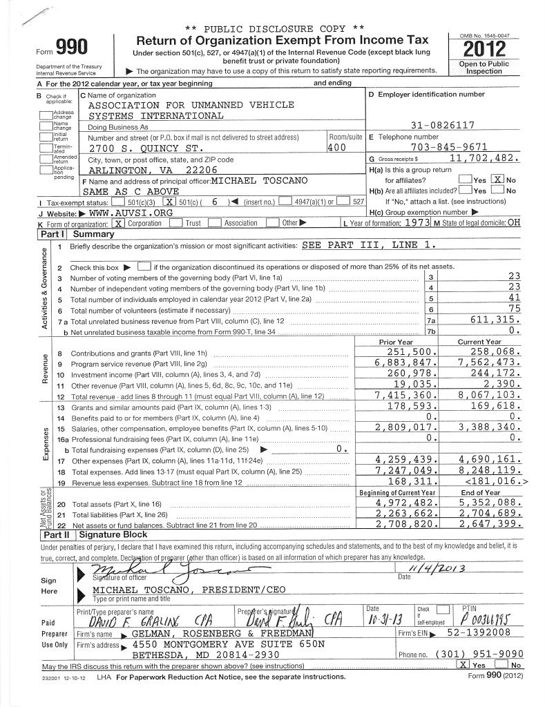
It would appear that a lack of resources is not the case. According to IRS Form 990, AUVSI’s Gross receipts for 2011 topped $11,702,000.00 including reserves in excess of $3,700,000.00 in stock (Members aim to find out whose stock we are holding.) The 990’s also document six-figure support for foreign chapters (Australia folded) while the domestic chapters get no financial support. Also puzzling was $301,931 in consulting fees for which the current Board Chairman told the Chapter President was spent on finding new markets for unmanned technology.
Does hiring an outside consulting firm to find expanding markets for the world’s “is the world’s largest non-profit organization devoted exclusively to advancing the unmanned systems and robotics community.” make sense? The best and the brightest are in the community and already understand well the emerging markets.
Furthermore, it appears that we are supporting a large staff with salaries and compensations totaling more than $3,388,000.00. Does that make sense for an industry with membership in regulatory limbo and who are suffering economically?
A DC salary comparison for 2011
Vice President of the U.S $230,700
Speaker of the House $223,500
Chief Justice, U.S. Supreme Court $223,500
CEO of AUVSI $216,520
Executive VP of AUVSI $182,962
U.S. Senator $174,000
U.S. Representative $174,000
Most of those on the list have a constituency larger than 7500 persons
Some of the other larger expenditures by AUVSI are $443,964 in travel expenses and $635,148 in equipment. We could only venture an uneducated guess about the travel and types of equipment purchased, but what figure the later was part of the furnishings for the $308,354 office remodel?
Whatever the case, I will again make my appeal to see the actual bookkeeping to better discern more effective ways of spending the memberships money towards the goals of membership building, grassroots advocacy and positive image building.
Link to IRS Form 990 (view the pdf)
Given the popularity of the 230/250 quads at the moment (blackout etc), I thought - wouldn't it be cool to have a rig that can do the ground skimming proximity stuff, but also with the normal "mod cons" of the APM?
Traditionally though, an APM would never fit. Until HK released the mini...so I built one.
I started with the Haldey-Bocks 230 frame, in Carbon Fibre. This was a mistake. I should have gone for the 250, because the fitting of the ESC's was a bitch of a job, especially with the thick 3DR power module hanging off it. And naturally, I forgot to solder in the XT for the video feed, so had to start again...
Anyway, this is the bare airframe:
So onto the fun part...
First, I fitted the camera, so I could make sure the clearances were good. I mounted it directly to the front CF plate to make sure I had as much room as possible behind it.
Second, I mounted the GPS antenna pole. This required a lot of trial and error, but eventually I found a position which worked.
Third, I fitted the APM mini in front of the post, and behind the camera. There is *just* enough room to do this. It is currently mounted with double 3M pads - I will review vibe damping after the first flight. Supposedly the blue balls do the "clean/dirty" thing, but is it enough to keep the APM within Z axis tolerances? Time will tell. These rcx are not the smoothest I have to say, and a propless spin up was really vibey.
I wired in the GPS, and the radio.
Then I mounted the 3DR telemetry radio to the roof. It is likely I will replace this with a minimOSD, and run a really simple OSD - volts, ground speed and home distance.
I then cable-tied the xt60 back on on itself on the PM - it was interfering with the props.
CoG is spot on, even though I thought it would be rearward.
Weight with tx will be 505 grams as you see it here. I have a wiring exercise to do (shorten and tidy), and to enclose the APM with some foam (for the Baro), and I hope that brings it down below the target 500 grams.
And that's it! It all fits together nicely. All the normal calibrations done - just compassmot to do (want to wait until I've got the camera and tx wired in first). Going for a really small 200mW 32ch 5.8. Will fit perfectly.
I didn't have time to get the thing in the air, but should able to get it in the air at the weekend. Can't wait to use DRIFT on this...:-)
Six months ago, Typhoon Haiyan devastated the Philippine’s South East coast. Now Drone Adventures is helping the reconstruction effort by providing much-needed aerial maps of the region.
Read the full article on Robohub:
http://robohub.org/aerial-drone-maps-document-philippine-typhoon-devastation-aid-in-reconstruction/
In my zeal to get started on my first multirotor I forgot to add a prop balancer to my cart! So I set out to make my own out of parts I had laying around...
My first prototype used a wooden drill bit because it fitted my prop perfectly at 6mm in diameter. Unfortunately because of the shape of the drill bit it would tend to one side, rendering any balancing done to the prop useless.
Learning from experience, I decided to go for as little mass as possible. A needle fitted the job description.
Next problem: How do you get a prop with a 6mm central hole to center on a needle? My answer came in the form of heatshrink tubing. Using very short lengths of heatshrink which I cut very carefully using a scalpel to ensure they were consistent I eventually got enough layers to slide the prop on.
Because heatshrink shrinks to the center, the prop is perfectly centered.
The key is to have as little mass as possible on the spindle. Using longer lengths of heatshrink produced an unbalanced spindle.
Below is a rough guide to making one of your very own using commonly available parts...
Please take not that I am not responsible for anyone's actions, use common sense!
Materials:
1x Large needle
2x Strong Magnets
1x Piece of wood for the base
2x pieces of wood for the walls
4x L Brackets
8x short wood screws
Lengths of small diameter heatshrink
Tools:
drill
dremel
heatgun
metal Shears
Step One:
Take your needle and shear off the eye. This can be hard so be careful and make sure no flying bits of metal hurt any one!
Step Two:
Put the needle into the dremel sharp end first. Now grind down the sheared end into a fine point using metal sand paper or on a grinding disk. This too can be a challenge because this stuff is harder than diamond.
Step Three:
Attach the two pieces of wood at 90 degrees to the base piece of wood using the L Brackets and the short wood screws.
Make sure the distance between the walls leaves enough room for the needle and two magnets. Also check that the walls are high enough so that the prop can rotate 360 degrees around.
Step Four:
Hot glue the two magnets to the walls, but be careful because magnets with molten glue on them have a tendency to snap together right onto your thumb leaving a nice burn, ask me how I know... :) .
Make sure that you hot glue the magnets facing each other so that they want to attract (north facing south or visa versa).
Tip: Magnets can be found inside microwaves and old hard drives.
That should be it! As you can see below there is virtually no friction between the needle and the magnets.
So now I am curious, I have spent the afternoon with my RCTimer Carbon Fiber props on the balancer and have been researching the best way to balance props, so I ask: How do you balance your props? More specifically what is best practice when it comes to balancing carbon fiber propellers?
As you can see in the picture below I have some copper tape strips to work with, but I am afrade that they will corrode plus they are an eyesore.
The best I have seen comes from U.A.V Advertising: https://www.youtube.com/watch?v=a3Byk8W5P_E
This method involves sanding the trailing edge of the prop.
I am planning on balancing my hubs as well as my brushless motors using lead tape.
So I put it to the community... what methods do you recommend? For those who advocate the tape method, what brands of tape have you found work best? For those who are in the glue/varnish camp, could you provide more detail?
Happy balancing!
Jethro.
This is F.L.O.O.P.Y. 42. The Robot uses 2 12 volt batteries(24v) controller is a dimension engineering 2x25. It is currently using a APM 2.6 with external compass and gps purchased from 3DRobotics.The drive system are 2 power chair motors
operating at 24volts.Also has 1240 maxbotic sonar on front left of vehicle.The frame is 3/4 inch angle with a plexiglass
platform.The shroud is from an old dehumidifier (lol).Also has 3drobotics telemetry (antenna seen front left.) The APM is
using a power module supplied by a 3 cell lipo 2450mah.Graphics are from build a sign.
I would like to thank everyone on this forum for their help in answering all of my questions during the build. And I
would like to shout out a special thanks to TCIII for his help especially compass calibration and setup.
See Video on you tube of new improved Floopy 42
 Moderators: Do not approve until consensus is reached. TCIII
An interesting interview with the CEO of Pal-V on a local radio station this morning making the statement that the flying car will be available for purchase at the end of this year. The first version, limited edition, will set you back about 500K Euro (a little less than 700K US$). A car license and a license for flying Gyrocopters is required to use the Pal-V
On the ground this slim, aerodynamic, 3-wheeled vehicle has the comfort of a car with the agility of a motorcycle thanks to its patented, cutting-edge, ‘tilting’ system. It can be driven to the nearest airfield and take off just like any other airplane. The single rotor and propeller are unfolded to make the PAL-V ONE ready to fly.
When airborne, the PAL-V usually flies below 4,000 feet (1,200 m), the airspace available for uncontrolled Visual Flight Rules (VFR) traffic; so there will be no interference from commercial air traffic. Furthermore, the PAL-V is powered by a very robust, flight certified aircraft engine. It runs on gasoline. It can reach speeds of up to 180 km/h (112 mph) both on land and in the air.
The PAL-V ONE has a very short take off and landing capability, making it possible to land practically anywhere. When not using controlled airspace, you can take off without filing a flight plan. Flying a PAL-V is like a standard gyrocopter. It is quieter than helicopters due to the slower rotation of the main rotor. It takes off and lands with low speed, cannot stall, and is very easy to control. The gyroplane technology means that it can be steered and landed safely even if the engine fails, because the rotor keeps auto rotating.
For more details, images and video's, head over to the Pal-V website: http://www.pal-v.com
I decided to build a new DIY drone, after my previous $10 balsa quad was flying (still fly) successfuly for me. And is still doing her job for aerial panoramas as you can see on AerialTasks. That will be converted into an X8, by adding another 4 motors on the samed frame, for a bigger camera.
This time I decided to go with am existent shell body frame and I optioned to use the QR X350 which is $30. It is the same size as Phantom.
You can see below step by step the progress with this quad.
It is designated to load a Hero3 with Tarot for FPV also (new pictures will follow soon with FPV gimbal).
Hope this is job which could inspire some other guys.
I am in the process of tuning this new quad.
Hi all
I'm glad to present you a video of an artistic project that I made one year ago:
Dronecoria (dronechory): an aerial platform for seed dispersal via nendo dango seed balls, for one-click reforestation.
Agro-hacking brazilian rainforest dispersing local seeds with drones.
This was just a proof of concept, I would like to build one cabable of carry at least 3 kilos of seeds ;)
But I don't have economical resources for build this kind of expensives multicopters with big payload :(
Here's a good Instructable on using the Plotly web service and Arduino to do basic quadcopter control and data analysis.
This project is part of a larger project involving the creation of a quadcopter. In this part of the project we want to collect the information of the sensor system that will be sent to the final user. The main controller of the quadcopter is based on an Arduino single-board microcontroller and the best way to send data via Internet is a WiFi shield. In this example, due to the lack of a WiFi shield, we opted for an Ethernet shield, although the code with both shields is not much different and can be easily adapted to a WiFi shield.
The materials used in this example are:
- Arduino UNO (you can use any Arduino)
- WIFI shield, or in our case an Ethernet shield, to connect with the Plotly web service. Additionally, these boards often incorporate a system to use a SD storage card, which allows us
Shield WIFI, or, in our case Ethernet shield, to connect with the Plotly web service; in addition, these boards often incorporate a system to use SD card storage, which allows us to store sensor data when we have no access to a WiFi or Ethernet network.
Sensors. Any sensor we want to obtain information either with direct connection to the arduino or with an intermediate conditioning. In our case we use the GY-80 IMU, affordable and with good results.
In the case you use an Ethernet shield you will need an Ethernet wire.
At least, you need power the Arduino, with batteries or USB wire.
Read the rest here.

Very interesting piece from Engineering.com about Skycatch, which uses a Pixhakw-based custom quadcopter for solar panel inspection:
Like many new technologies, Unmanned Aerial Vehicles (UAVs) started with military applications and gradually found their way into civilian life. With support from investors such as Google, a new company called Skycatch has developed a UAV that’s used for remote monitoring and inspecting construction sites, mining operations, and farms. Now Skycatch is getting into the solar array inspection business. It will soon begin testing its technology on PV farms built by industry giants SolarCity and First Solar.
Infrared Signatures Show Defective Panels
Photovoltaic panels emit a certain amount of heat, and it turns out that defective panels give off more heat than functioning panels. The difference in temperature can be easily detected using an infrared thermal imaging camera, as shown in the image below. A quick flyover by a UAV armed with an IR camera can identify malfunctioning panels quickly and inexpensively, allowing operators to replace the panels and keep the solar farm running at peak efficiency. You won’t see these flying over residential rooftop arrays; it’s only cost-effective for utility-scale solar farms.
The Vehicle and Base Unit
The Skycatch quadcopter weighs about 2.3kg (5 pounds) and is armed with a variety of sensors, depending on the application. For solar farm inspection, it uses a Tau IR camera, which adds only 70 grams to the overall weight. Autonomous navigation employs GPS and sonar, and the quadcopter can also be operated by remote control when necessary. It can fly 80km/hr (50 MPH), reach altitudes of 120 meters (400 ft), and maintain its position under windy conditions; its drift is about 30 cm (1 foot) in 40 km/hr (25 MPH) winds.
The copter returns to its base unit to dump its data and have its battery replaced. Once the quadcopter is docked, the base unit’s robotic arm swaps out the weak battery and replaces it with a fresh one from a carousel. Each battery pack includes 15 GB of storage; its data is then uploaded to cloud-based storage using the base unit’s WiFi connection.
Will It Fly?
Not the drone, of course - I know that flies. But will UAV inspection of PV farms make a significant economic impact on solar energy production? The National Renewable Energy Laboratory (NREL) estimates that PV panels suffer a failure rate of less than 1% per year, which doesn’t seem like much, but it adds up over time. Given the relatively low cost of UAVs, it’s probably worthwhile to have aerial robotic inspectors doing a flyover of a solar farm once in a while.
Images courtesy of Skycatch.
Hi all. Been a while since I posted, but thought I'd give a bit of an insight into what I'm doing with "Terence" - my medium lift/endurance quad. And today is as good a day as any, as I got the latest CF samples in. And it's partly it's the start of the build instructions for when it goes live So lets build...
Part one is the main airframe, part 2 will be the electronics.
1. Construct the sensor tray, and attach it to the bottom of the battery tray. The space is for the PXflow board - obviously you won't be running all three at once. Of course, I added the Swiss flag at this point, naturally...I also added the rubber for the battery bay - this is the non-slip stuff you get for your car dashboard to stop your phone slipping around.
I also inspected the CF - measurements are all good, and the reduced thickness has shed some weight, and hasn't really lost too much strength. Certainly strong enough to hold the optimal payload (16,000mah 6S). I have a picture with it holding 4 x 4500 in 4S...that's 18,000mah (4S). So should have good flight times.
I still need to get a pxflow to test these mounts. This plate will need recut, after the tolerances for the optiflow failed - you can see the lens touching the CF. I need to cut that section out. The sonar peg holes could do with a tiny (0.5mm) bit of adjustment as well.
2. Added all the standoffs to the bottom plate. I'm using the extended ones for the battery plate, but that's ok - it's part of the design to be able to extend the depth of the battery bay. Production ones will be cylindrical and black. I'm 50:50 on whether to use nylon ones, give there will be up to 2kg of battery to support over 9 pegs. They're certainly cheaper and lighter. Hmmm...
3. Then I mounted the nex5 gimbal, so I could get the peg position...then removed it, while leaving the pegs in place. There is a reason for this - if you leave the gimbal in place, you can't screw down the PDB! They both share the X-shaped guide - the idea being that pretty much any gimbal/payload and PDB can be mounted there. As you'll see later. This version has the battery bay moved backwards for better CoG, but I may still push it back further; a 1kg weight mounted here still has the CoG forward of CoT by 2cm (the old one flew ok with nearly 5cm).
4. Added the PDB, and mounted the ESC's in place, and Covered them the with the shelf. Another set of ESC's can go on top, to give a XY8, but we're building a conventional Disco-style quad. As usual, I labelled all my ESC's with motor number.
The Gryphon has been modified by using smaller standoffs - I wanted to make sure the PDB and the BEC disc fitted in the frame safely. 8cm Power cable extensions were required for 2 of the ESC's, but apart from that, it's working out nicely. i could have gone for a convention PDB, but I needed to test the clearances of the big ring (especially important for high-draw X8 config).
I was concerned about cooling, but previous prototypes showed this to not really be a huge problem if your ESC's have a decent overhead.
5. Attach all the standoffs and GPS post to the top deck. You can see the mount holes for the pixhawk accessories here.
6. Then the tedious job...attaching the arms! I'm not happy with these M2.5 clamps. The clamps (aluminium) are perfectly strong, but the m2.5 bolts are just too prone to rounding if you crank up the torque. I'm going to redesign around m3 clamps. Some drilling was required on motor arm 4, after I managed to not update the size from last time. #facepalm.
7. Then we add the battery tray we build earlier, and add the top cover for the electronics. So far, everything is fitting like a glove.
Bingo! Time for the electronics in the next post...
Imagine your drone suddenly running low on power - a long way from home, doing it's auto waypoint flying thing.
You have to decide how, where and when to set it down very quickly!
I've been playing with my homebrew Automatic Landing Finder (ALF) that uses a photo to determine where a suitable landing spot would be. The algorithm takes things such as size, visibility etc. into account when determining what spot to pick. The system picks the best candidate among possibly thousands.
The idea is to have a camera pointing downward taking snapshots at regular intervals. Should things go haywire, the system will analyse the last frame where the craft was till stable, and try to find the best landing spot.
Eventually this system will be installed on the next version of the USAV (Unmanned Social Autonomous Vehicle) but for now it's being tested with "fake" images from google earth.
If you had to land anywhere on the picture below, where would it be?
Feeding the image above though the ALF reveals the places that ALF considers as being a more or less good spot to land. The resulting image is greyscale because this is a part of the process. Yellow squares are suitable candidates, and the red square is the chosen optimum landing site. Observe how dark spots (where poor visibility prevents a proper condition estimation and vegitated areas are (mostly) avoided. Did you chose the same spot?
How fast did you determine a proper place to land? The computer took roughly 842 ms to find a good spot.
Below is the same result with all candidates removed, only showing the optimum landing site.
I'd love to get some feedback on what you flying guys out there think is a good emergency landing spot in general as well as what is a bad one! :)
Best regards
Jesper Andersen
A research team led by Jarrod Hodgson and Rohan Clarke from Monash University is partnering with ConservationDrones to use UAVs for seabird monitoring. Jarrod and Rohan have just returned from a successful trip to remote islands in north-western Australia. They brought along a 3DRobotics X8 multirotor UAV which they used to capture very high resolution images of nesting seabirds on these islands.
The team from Monash University made a total of 9 successful flights with the UAV. They were targeting colonies of Crested Tern and Lesser Frigatebird. The Crested Tern colonies represent a medium-sized species that nests in dense colonies on the ground (see picture), whereas Lesser Frigatebirds are a large seabird which nests in smaller groups typically on elevated nest stacks and within vegetation.
For every successful survey, the team dispatched experienced seabird counters to make 1 – 2 blind counts of the surveyed population. They will be comparing these ‘ground counts’ with UAV aerial counts to assess the reliability of UAV data.
This is a fantastic demonstration of yet another application for conservation drones. The ConservationDrones team is excited to continue our collaborate with Jarrod and Rohan in several upcoming projects. Check out their new project site: ResearchEcology.com.au!
Impressive! They're big and heavy (19 lbs) but so cool. More here. (Via Makezine)
I just released the findings of my two month survey studying the impact of FAA rules on small unmanned aerial systems (sUAS) in the U.S. You can read the press release here.
Among the many insights I got from the research, these two are the most significant:
“Impact of FAA Rules on sUAS Business” examines the economic impact of current FAA policies for sUAS operating in Class G uncontrolled airspace. It evaluates how commercial service providers and operators perceive those rules and assess their importance.
Read more here: http://droneanalyst.com/2014/05/03/will-future-faa-rules-kill-the-small-drones-market/


