A team of people who had worked at Joby Robotics, who were doing the UAV-as-energy-generating-kite thing we wrote about earlier (which I gather didn't work out, sadly), is trying to raise money on Kickstarter to turn their hybrid quad-plane aircraft into a commercial product.
The Quadshot is a remote-controlled aircraft we have created that melds advanced Open-Source hardware and software with a unique airframe design. It can both fly forward like an airplane and hover like a helicopter - but without the usual complicated, expensive, and fragile moving parts.
It uses the Lisa Paparazzi IMU, but isn't meant to be a UAV. Instead, the electronics serve as a pilot assist, and you can switch from copter to plane to acrobatic combo with a flick of a RC switch. $500 to pre-order the version with the IMU.
Continuing with the 3D Printing theme, here's an adorable little quad frame that's available from Thingiverse, the datasource for the Makerbot.
From the description: "This is a fully parametric, fully printable, quadrocopter frame design done with Inventor. With this design you can print a quadrocopter with a 160-260mm motor to motor distance, giving enough room to accommodate props from 101.6mm (4") to 177.8mm (7")."
Looks like a nice little unit, good at least for a testing platform for instrumentation, etc.
As this site becomes bigger and attracts more attention, I'd like to emphasize to new users and old that a big part of our mission is promoting and protecting responsible use of UAVs. We have encouraged regulators, defense organizations and law enforcement agencies to join this community to become better informed about what's possible with small UAVs, and many have done so.
If you are not already aware that what you say here may be read by police and regulators, you should be. They're here and are paying attention. I personally think that's a good thing, and I spend a lot of time with such organizations explaining what we do and inviting them to participate. Our message is this: the site is for peaceful, civilian use of UAVs, which is the big new area that we're collectively working to build here. Anything else is banned.
To make this as clear as possible, I've added the following to our site policies:
7) No discussion of illegal or harmful use of UAVs will be tolerated. Responsible use of UAVs is at the core of our mission. That means conforming with all laws in the United States, where this site is based, and insisting that our members elsewhere follow the laws of their own countries. In addition, we feel that part of our responsibility it to help the relevant authorities understand what's possible with amateur UAVs, so they can make better-informed policies and laws. So we have encouraged all relevant regulators, defense agencies and law enforcement agencies to become members here and even participate to help them do that, and many have. In addition, if we see any discussion of UAV use that we feel is potentially illegal or intended to do harm, we will bring it to the attention to the relevant authorities, and will comply with any legal request they make for information about users (although we don't know much that isn't public; see the next item).
8) Your privacy is protected, up to a point: This is a social network, so everything you write and post here is public, with certain exceptions: 1) Your private messages are private. Administrators are unable to see them, nor can anyone else other than the recipient. 2) Your IP address is private. We are hosted on Ning, which controls the server logs. DIY Drones administrators can only see your username and email address; they cannot see your password and do not have access to your account.
There are some nice new approaches on frame construction out there.
This Korean guy found a nice way to get more thrust and it has also a good open space in front. Looks interesting to fly with cameras. I enjoy the idea. Sounds good. Don't you think?
There is also this other one "ButterflyCopter" with same idea but... 10 motors!!!
Here we can see how nice is the result of a camera aboard:
Hi all, On popular request, here's a short tutorial on how to make a low battery warning on my hexa with blinking leds, as you can see at the end of the following video :
EDIT : The software changes in this blog are now outdated and not necessary anymore. For the new software see my new blog with much more possibilities (without using the relay) : U4eake's showleds, arming and low battery warning leds
Furthermore I'll use this as a reminder on what to change in my code when new versions come out :-)
First I'll give proper credit where credit is due, this code was originally written by Bill Sanford and posted on rcgroups here : Bill Sanfords running lights. They are originally intended to be run with a brushed esc, so they can pulsate.
I have a lot of them, so they draw much more current then the outputs of the APM can provide, but the relay has no problem with it.
General principle :
I have the leds setup as follows : on arming motors, the leds go on, indicating the copter is armed. On disarming they go out.
When battery voltage reaches 10.6V the leds start blinking slowly (2 Hz). From experimenting I know that I now have about 1 min of flighttime left with my battery. You may need to experiment yourself to find out how much you have left.
When voltage goes down to 9.9V, it's really time to land (about 15s left) and the leds start blinking rapidly (5hz). This is also the time when the copter will go into RTL, unless you modify the code (will get to that later on, see software, point 3. event.pde)
Hardware :
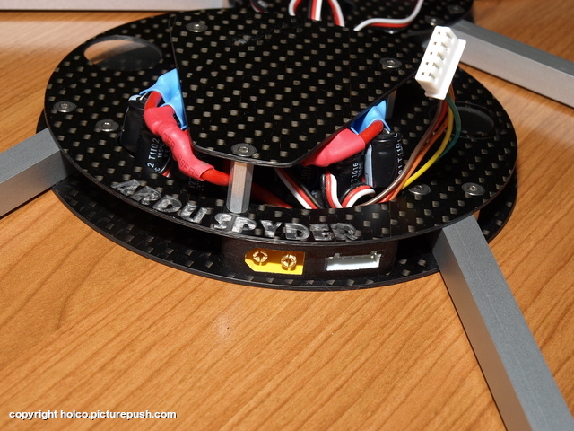
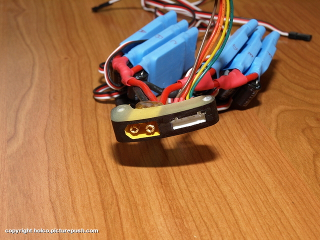
First the hardware. I soldered a 3S balancing connector to the relay ports of the IMU as shown in the pictures. Yellow wire goes to pin AN0 on the imu. Red wire goed to middle pin of relay.
PAY ATTENTION : on the 3S connector, swap the black and yellow wires if you use standard 3S balancing connectors !!! Standard 3S balancing connectors have the black wire on the rightside end in the picture below. On the imu however, the third pin is ground and the rightmost pin is AN0 which should be connected to +12V. So swap the wires if you're using a standard 3S balancing connector or you'll invert polarity and damage your board !
Then on the other side of the imu, solder the ground pin together with relay pin 0 with a solder bridge. Also solder a short wire, connecting the pin AN0 (yellow wire) to the right side relay pin (pin 1).
Now connect Yellow to battery +12V and black to battery minus. Connect red to leds+ en blue to leds-. All leds should be connected in parallel to the red and blue wire. Don't overdo it though, the relay must be able to handle the amps. 60 hobbyking leds (1m) is still fine. If you want more, check ampdraw en relay specifications.
With relay in pos 0, the red wire (led+) is connected to ground, so leds are off.
With relay in pos 1, the red wire (led+) gets fed +12V comming from Yellow wire at AN0.
Furthermore AN0 is constantly connected to +12V from battery so it can monitor battery voltage.
Your hardware changes are now done.
DISCLAIMER : I assume if you do this that you have sufficient knowledge about soldering and electronics. Even though I tried to explain as best as I could, I take NO responsability if you destroy your board doing this. Do this at your own risk !
Software : These changes are no longer valid, see my new blog mentioned above for recent code !
You'll need to make the following modifications the the firmware and then compile and upload with arduino.
1. In ArduCopterMega.pde
Find the medium_loop() function and in it find case 4. There is a call to the read_battery() function there.
Insert a call to handle_relay_lights() right after the read_battery() call. See red text below.
ArduCopterMega.pde is now ready. Don't forget to save it !
2. APM_config.h
Add the following code :
#ifndef BATTERY_EVENT
# define BATTERY_EVENT ENABLED
#endif #ifndef LOW_VOLTAGE
# define LOW_VOLTAGE 9.9
#endif #ifndef MID_VOLTAGE
# define MID_VOLTAGE 10.6
#endif #ifndef VOLT_DIV_RATIO
# define VOLT_DIV_RATIO 3.33
#endif #ifndef INPUT_VOLTAGE
# define INPUT_VOLTAGE 5.26
#endif
// global variables for motor leds and battery monitoring through onboard relay
int rl_state = 0 ; // this global variable is used to save the on/off state of the relay
int rl_counter = 0 ; // this global variable is used for the flash rate timer
I know the variables should probably be defined in parameters.h but upto now I've been too lazy to do so... If you want to, pls do so, but bear in mind that it's an extra file to modify each time a new firmware comes out.
That concludes the APM_config.h modifications. MID_VOLTAGE is when the lights start flashing slowly, LOW_VOLTAGE is when they flash rapidly and when copter goes into RTL.
You may have to experiment a little to find the right values for you. See also the wiki about battery monitoring.
3. Events.pdeAs of version 2.0.38 this step is already implemented in Events.pde, no need to change it.
Since I now have leds to warn me when battery gets low, I don't want the copter to unexpectedly go into RTL cause my leds have been blinking and I didn't land in time. One time when I was testing this, hoovering low with blinking lights, my copter suddenly took of and flew into the hedge. Luckily I wasn't in between.
So I only want the copter to go into RTL when he's flying on an automatic mode (auto, loiter), not when I'm in control.
Find the line void low_battery_event(void) in the event.pde file.
Change the whole function to look like this (red text changed) :
I am thinking hard if it wouldn't be better (if possible) to change it into set_mode(Land); to have the copter land on an empty battery instead of attempting to get home with no juice left (which will probably end in disaster if the copter is more then 15sec away from home)
4. RunningLights.pde
Add the file RunningLights.pde to the directory where ArduCopterMega.pde is located. This is a new file to add. You can download it below.
That's it !!! Compile and upload with arduino, enable battery monitoring to battery volts in setup (type setup in CLI and then battery 3) or choose battery volts in mission planner -> hardware setup -> monitor.
That's a new fancy stencil printer coming in, beside one of our pick-and-place machines at the 3D Robotics factory in San Diego. All sort of new equipment is in place, including the new reflow oven, automatic glue dispenser (for two-sided boards), lots of smart feeders for the pick-and-place etc.
All this automation and high-quality equipment has meant a massive improvement in board quality and yield. Our aim is to produce the most reliable and robust boards in the industry, and this kind of investment will help us get there.
We'll be moving to an even larger (8,400 square foot) space in the next few weeks, in anticipation of ramping up with a bunch of new products. If you're in San Diego and want a tour, ping me and I can arrange a time with the team there.
While drones are now in heavy use by the U.S. military in our wars abroad, and to a certain extent by U.S. law enforcementwithin our country’s borders, the use of drones byprivateentities is still a highly-regulated and legally murky area. A big part of the reason for that are the privacy issues raised. Robot guru Ryan Calo, director of the Stanford Center for Internet and Society, has voiced concerns to me (and toNPR’s Marketplace) about paparazzi drones that could be used to fly around using facial recognition technology to find and obsessively photograph Brad Pitt.
I started digging around to find out exactly what’s required for a private business to get itself a drone and start buzzing it around. I’ve been going back and forth with the Federal Aviation Administration about “unmanned aircraft” for months. Hobbyists are basically free to use drones as long as they keep them under 400 feet. At this point, civil and commercial use of drones is only allowed for research and development purposes. “Not for compensation or hire” says oneFAA notice. To get government permission to use a drone (for non-hobby purposes), a private entity has tojump through hoopsincluding getting an airworthiness certificate — meaning the thing is safe to fly — and an experimental certificate, approving the planned use of the unmanned system (uses are currently limited to research and development, marketing surveys, or crew training).
The FAA told me earlier this year that the Unmanned Aircraft Systems office has issued 83 experimental certificates for 20 different kinds of drones. “Currently, 18 of those experimental certificates are active,” said spokesperson Les Dorr. The FAA declined to identify the companies that hold those certificates (and have not yet responded to a FOIA for those names). “An experimental certificate allows the holder to do tests, training and demos but not for-hire operations. Ops also must be conducted away from populated areas,” added Dorr.
The News Corp’sThe Dailyhasa dronethat it’s sent out a few times, as noted byThe Observer. After The Daily broadcast some incredible footage of Alabama after it was devastated by storms, UAS Visionreportedthat The Daily owns a MicroDrone MD4-1000. The Daily sent it out again in June to bring back video from Minot, North Dakota after intense flooding there. (Total non-sequitur:Drones can hack cell phones now, you know.)
Taking footage for news-gathering purposes seemed like a commercial use of a drone, which is a no-no, as I understand it. I followed up with the FAA asking if News Corp was one of the companies with an experimental certificate. The inquiry got lobbed to the FAA’s legal department…
“We are examining The Daily’s use of a small unmanned aircraft to see if it was in accordance with FAA policies,” said Les Dorr in an email today. A Daily spokesperson has not yet responded to an inquiry about ownership and licensing of the company’s drone.
Using drones for news-gathering seems like a pretty cool idea, though it’s easy to imagine the robot paparazzi future that Ryan Calo fears. While FAA regulations may currently prohibit such a use, the agency is planning to revisit — and possibly relax — those regulations this year, potentially making it easier for private companies to fly the friendly skies with drones.
The Sooner State, for one, is trying to pave the way for that future. Asnoted by drone guru Calo, the state of Oklahoma “has taken steps to reserve an air corridor for the domestic use of autonomous drones. If approved by the Federal Aviation Administration, this would free up an 80 mile stretch for the military, hobbyists, and others to operate drones in U.S. airspace.”
So perhaps we’ll be seeing a lot of drone-enabled news out of Oklahoma soon. Celebs may want to steer clear of the area.
We've written about this before, but I'm not sure everyone's seen the video. It's a really impressive production process. No doubt heavier than foam and possibly balsa, but that will improve over time with new materials.
Sold as a multiple rx buddy box, can be wired in a way that the rx is connected to the master input, the computer connected to the slave input, and if the computer looses it, you can switch to manual, overriding almost everything.
Posted by James Goppert on August 2, 2011 at 11:00am
An object oriented fork of the APM autopilot code supporting multiple vehicle types and with the goal of supporting multiple ArduPilot boards in the future (currently only ArduPilotMega).
Some clarification:
It started as an object oriented (C++) branch of ArduPilotMega. It provides an abstraction layer between the different modules of the autopilot so that they can be shared among different vehicle types. After several discussions, we on the development team choose not to use it as a base for ArduPilotMega and ArduCopter. Think of it more as ArduPilotMega++ if you like.
Currently ArduPilotOne supports: rover(full autopilot), quad (manual flight), boat(full autopilot, not yet tested), plane(full autopilot, not yet tested)
The quad full auto support will be online in a month or so when I have time to sit down with my arducopter again and get the rest of the gains. This isn't meant to compete with ArduCopter, ArduPilotMega, it is simply a different option if you want something that you can have the same code base and is object oriented. The quad/plane code doesn't have nearly as many options as ArduCopter/ ArduPilotMega, but for my research with multiple vehicle cooperation I want a platform where all vehicles run the same c++ code using different modules for unique vehicle differences. It is fairly extensible so it will be easy to add more options as needed.
Notes:
1. There is no command line mode.
2. You must run it with a ground station talking mavlink. If a mavlink packet is not received by the vehicle from the ground station it will go into a failsafe mode.
3. The main ardupilotone.pde sketch is meant as a template. You can easily copy it and modify it to your liking in a different sketch.
4. In ardupilotone.pde the vehicle configuration file is included. Make sure you include CarStampede.h if you want to test the ArduRover functionality. PlaneEasystar.h if you want to test the plane, BoatGeneric.h if you want to test the boat, QuadArducopter.h for the quad etc.
5. Feel free to make your own vehicle config file for your specific vehicle, you can use the others as a template.
Cool on multiple levels. (Insert obligatory "This is how Skynet becomes self-aware!" joke). From hackaday:
Swarm robotics is really starting to produce some interesting results. This image is from the video embedded after the break that show a group offive robots creating a landing platform for a quadrotor helicopter. The four that actually make up the platform are not in contact with each other, but instead following commands from the leader. We’re impressed by the helicopter’s ability to target and land on the moving platform. Takeoff appears to be another issue, as the platform bots stop moving until the quadcopter is airborne again.
These robots are part of a Graduate project at Georgia Tech. [Ted Macdonald] has been working along with others to implement an organizational algorithm that guides the swarm. The method requires that the robots have an overview of the location of all others in the swarm. This is done with high-speed cameras like we’ve seen inother robotic control projects. But that doesn’t discourage us. If you already have a flying robot as part of the swarm, you might as well add a few more to serve as the eyes in the sky.
Join Team BlackSheep and associates for a weekend of formation flying in the alps. This video changes the perspective a bit, and gives lets you view our planes from the ground.
The ArduCopter & ArduPilot Mega telemetry kit utilizes the Xbee Pro 2.4 GHz 63mw modules; this is the kit for use in the UK, EU and other parts of the world where the 900 MHz Xbee’s can’t be used due to mobile phones using the same frequency.
This telemetry kit supports two way communication with the mission waypoint read and write functions in both Michael Oborne's Mission planner and HappyKillmore’s GCS on both the latest APM and ACM codes. This means no more USB cables & landings to connect the ArduPilot to a laptop in the field, you are able to view live telemetry data as your airframe progress through the mission, you can load a new mission on the fly while your UAV circles above you and execute that new mission without having to land! The range of operation has been tested out to half a mile with no loss in connection, connection has been found to drop off at 3/4 of a mile.
Included in the kit are all the items you need to have a fully functioning telemetry system:
2 x Xbee Pro’s series 1 (1 x whip antenna 1 x RPSMA).
Ground and airframe adaptor boards (2 x XteamBee's).
Either as a pre soldered, fully programmed and tested kit, so they are completely plug and play or in a self built kit, for those of you who like to build your own. The kits are now in stock at www.buildyourowndrone.co.uk
The 2.4Ghz Pro series 2 Xbees (firmware XBP24-ZB, XBP24-B) do not work with the DIY Drones Xtreme Bee boards. Please use Sparkfun Xbee explorer boards.
Instructions:
Build the Xtream Bee’s:
The XtreamBee boards need to be built, this involves some soldering and is not complicated if you are experienced with soldering, however a word of warning here, when soldering the female headers, don’t use too much solder! The male pins of the Xbee modules will not fit into the female headers if any excess solder runs down inside the holes on the PCB, it will fill the female headers with solder, this is not good!
When the soldering of the female header connections is complete you will have to solder the connection pins for the FTDI / telemetry cable to the APM and the computer. To enable the to way communication in the GCS’s you will need to hold the CTS line high, this is done with a solder bridge from the VIN line to CTS line. This modification is required on both XtreamBee boards with FTDI connectors, it is not needed with the USB GCS XtreamBee board now supplied in the kit.
When you have completed the construction of the XtreamBee boards set both slide switches to master mode, you can now add the first Xbee module to the XtreamBee, you will see that there is an white outline of the Xbee on the board for orientation, please ensure you select the correct orientation to save the XBee unit from being damaged!
Before adding any power to the board make sure that the Antenna on the RPSMA Xbee is attached and screwed all the way on, powering the unit without the antenna being fitted or incorrectly fitted will cause the unit to fail!
Install the Xbee’s and Program:
When the Xbee is fitted to the XtreamBee and the antenna has been connected power the first board using the supplied FTDI cable, note the orientation of the lead colours (see image above), the black wire needs to go to the pin marked “BLK” on the top side of the board or “GND” on the underside. If this is placed correctly you cannot get the other connections incorrect!
The Xbee’s come set at a data rate of 9600, this needs to be changed to the higher rate of 57600. To do this you will need to use a free program called X-CTU
In "PC Settings" select the comport that the XBee is connected to, then go to the tab marked "Modem Configuration". Always select the update firmware option, click "Read", change the rate in the box shown above and then click "Write".
When you have changed the rate on the first board, remove the first Xtream Bee and switch over with the other, program the second one in the same way and to the same rate as the first.
The set up of the Xbee’s are now completed!
Adding the Telemetry to APM:
On the APM you will see that there is a total of four connection ports marked "Teleport", (if you don't have the male pins to solder to the teleport for fitting the telemetry cable they can be found here) which will need to be connected to the airframe part of the telemetry kit. There are two pins for the power and two for the communication. Once again if you look at the XtreamBee you will see there is a “5v+”, “GND”, “In” and “OUT”. With the supplied APM telemetry cable you will find one end has 4 connections and the other has 5, the 4 goes onto the APM and 5 onto the XtreamBee, match the two ends to the corresponding pins and the APM is ready to send telemetry data to the GCS.
How to get the data:
To start using the telemetry, power the APM first which will power the airframe Xbee, power the GCS Xbee second, then load the Mission Planner or HK’s GCS select the correct comport and speed (57600) and click connect. You will now have your telemetry up and running!
Always select disconnect in the GCS before removing power from either of the units, I have found that on odd occasions if you just unplug one unit / switch the power off without disconnecting in the GCS you can lock a unit, this is easy to solve by reprogramming the XBee again, but to avoid it reverse the connection process.
Tests:
Use of 2.4 GHz Radio and Telemetry together:
This kit has been tested both in the field and in a lab environment to check for any clashes or interference between the RX/TX of the radio equipment operating on the same frequency as the Xbee’s, no conflicts have been found to exist.
The Xbee units on power up look at the frequencies available in the channel they have assigned, they will then select the one which has the least amount of noise, this is called DSSS in the world of Xbee’s, the DSSS operates in a very similar way to that of the 2.4 GHz radios with frequency hopping, which means we can fly more than one aircraft at a time and still use the same 2.4 GHz band as the pilot standing right next to us.
The field tests conducted were first with the radio on “range Check” which is a very low power setting, the Xbee was set to full power and placed on top of the RX and APM, the TX was taken to the minimum recommended distance and some way beyond, at which point there was still a solid lock and smooth operation of all the connected servos.
The second field test was conducted in a wide open space, where once again the Xbee was set to full power and was left on top of the APM and RX, the TX was in normal “flight Power” mode and was taken to approx 1.3 miles away with line of sight, there was no loss of connection to the servos, they still operated as if there was not a telemetry kit working right next to the RX.
The radio I used throughout all of the field testing was a Futaba T7C, I have also released three full test kits to customers to try with additional radio equipment, all non Futaba, some of the radios tested were $60 specials while others were top end systems, all tests conducted have proven to be successful with no loss in control at any time and easy to use telemetry from the box.
While no concerns or issues have been identified with the telemetry kit and the radio systems when tested in the field or lab, it's highly recommend that a “range check” be carried out before committing to flight, if you can maintain a solid RX / TX lock at lowered powers on the ground beyond the minimum distance recommended then flight should not be an issue.
Here's a really impressive DIY quadcopter from the smart guys at Let's Make Robots. It uses custom firmware running on a hacked Fonera wifi router and regular Wii sensors to fly with a joystick via wifi.
Atropos is remotely operated by a wifi link, powered by a Fonera router. The user can pilot the aircraft with a HTML5 and canvas web interface, making AJAX request on every key stroke or mouse movement. Telemetry is received with COMET (SERVER Push) HTTP information and Javascript is used to manage the entire page.
Fonera sends rotor commands to a 16F876 PIC, which generates PPM signals to manage ESC ( Electronic Speed Controllers). Those ESC are the power stage to trifasic motors.
To achieve very fast and less time consuming requests, http router web server has been modified on it's source code, to process all the AJAX requests in a RAM shared memory portion on the router.
Thelast effort ofFoxTeam, through collaboration by meandAleBS the resultiscomplete framewith Gimbalthat we were ableto put togetheron aMP32.
Theframe issimple, practicaland light. We are workingto make itmoreimmune tovibration.The configurationand flight'QuadXsupports aGimbalableto takecomfortin the airaGoProHDor acompactcamera.He haslonglegsthat will allowin the futureto putanother 4engines, and thena fineand maybe abigger gimbal.
Maybea futurerevision couldbe madeof carbonfiber ,there isalreadyin progress a versionHexaradial.What do you think?
Are welcomesuggestions to improve theframe ...
You need a PPMSUMradiowith at least 8channelsto get allthe necessary control channel, oralready'withseven channelsyoucan'control thetilt.
L'ultima fatica del FoxTeam, grazie alla collaborazione con Ale questo e' il risultato del frame completo di Gimbal entry level che siamo riusciti a mettere assieme su base MP32.
Il frame e' semplice , funzionale e leggero , stiamo lavorando per renderlo immune il piu' possibile alle vibrazioni .La configurazione di volo e' Quad a X , supporta una Gimbal in grado di portare in volo comodamente una GoProHD oppure una telecamerina compatta. Ha gambette lunghe che consentiranno in futuro di mettere sotto altri 4 motori e quindi fare un bel okto coassiale e magari una gimbal un po' piu' grandicella.
Magari una prossima revisione potrebbe essere fatta in carbonio , c'e' gia' in lavorazione la versione Hexa radiale. Che ve ne pare ? Si accettano consigli per migliorare il frame ... Serve una radio PPMSUM con almeno 8 canali per avere tutti i controlli necessari oppure gia' con una sette canali si puo' controllare il tilt , per farlo dal secondo pilota si puo' prendere una radio e collegarla tramite il cavetto maestro alievo.
Posted by James Goppert on August 1, 2011 at 12:00pm
The ArduRover (based on ArduPilotOne) user base is growing and it is time for a beta release. Right now, as the core developer, I do not have enough time to test the code thoroughly on all platforms. If you have an unmanned rover, boat, or quad, and a mavlink compatible ground station (free for download/ qgroundcontrol, hk gcs etc.) then feel free to become a beta tester.
As the community grows, documenting the code behavior for the end user will be important. A comprehensive wiki like the one currently available for ArduPilotMega would be a huge help. So if you can contribute to the documentation also contact me and I'll get you added to the google code project.
Finally, if you have C++ coding experience and have patches to the code for improved functionality feel free to send them to me. If you submit enough helpful patches, I'll invite you to the development team.
This is new to me and kinda amazing. The paraglider pilots train hawks to find thermals for them, then reward them with food. It's called "parahawking".
You know what would be better than a hawk? A little UAV programmed to do the same thing. They don't need little bits of meat all the time. Just saying....


.jpg)