So I know this isn't exactly "DIY Drone-ish" as far subject matter, but I thought the interview was pretty interesting as Greg's approch to designing and testing new concepts and his RC Super Hero were so unique that it deserved to be shared.
Greg runs the YouTube channel "BornTaFly" and sells his models and PDF plans through www.RCSuperHero.com
Over the last few months we have been testing our new hardware, launcher, airframe and autopilot. As the newest member of the team I've been taking responsibility for producing some new videos - the acquisition of a GoPro HD has resulted in some amazing footage. Such great video from such a small device!
This video shows a short flight of our 2.8m wingspan flying wing airframe. Currently powered by 2 LiPo and an electric outrunner, we plan to integrate a 4-stroke petrol engine in the coming weeks:
The second video is some test footage flying with a HobbyKing Fox glider and our autopilot. We have successfully performed hours of autonomous flight with this system and the next stage will be to integrate this into the flying wing airframe from the previous video.
"At Project Andromeda, we are developing a reliable autonomous unmanned aerial vehicle for use in Civilian applications. Our endeavour is to create a cost effective and reliable method to perform aerial surveying and photography for civilian clients."
For the next version of APM (the fixed-wing codebase), we're thinking about adding an acrobatic scripting language, so you can program your UAV to do awesome robotic stunts. APM already suppports inverted flight, and adding other maneuvers is technically easy once we decide on how to program them.
As a comparison, the UAVDevBoard uses LOGO as its scripting language and also supports inverted flight and harrier/hovering. APM does its scripting with MAVLink via the Mission Planner or HK-GCS, which is a more visual way to plan a mission.
One option is that we could add MAVLink commands that took the following form:
Roll (rotations/distance, rate)
Knife-edge (duration/distance)
Loop (radius, degrees)
Harrier/hover (duration)
Acrobatic commands would be executed in parallel with waypoint commands, so you could script the position, too.
What do you think? What's the best way to script acrobatics?
Hack-a-day has a good write-up of ScoutUAV, a custom-built quadcopter using the APM hardware and ArduPirates code. It really is a terrific site and introduction to building an APM-powered quad:
DIY-er [Russell] wanted a quadcopter, and like many people out there, he knew the satisfaction that would come from building it himself. Rather than purchase a kit or follow a set of online instructions, he spent a lot of time researching quadcopters, and eventuallyput together a thorough tutorial himself.
His Arduino-based quadcopter is named Scout and runs about $1,000 to $2,000 depending on which parts you choose to buy. [Russell] has a complete parts list available on his site, including plenty of alternate component choices for builders on a budget.
He covers the construction process in great detail, discussing frame fabrication and component placement as well as how to program the Arduino for the copter’s first flight. He also takes the time to break down his component list item by item to explain how each piece is part of the greater puzzle, which is great for first time builders.
We love seeing this level of detail when discussing a build process, and as you can see by the video embedded below, his quadcopter looks great!
Today i 've tried my little Y6 (90 degree arm) with an 3000 maH Lipo !! here is the result !! really Powerfull !!
I attach the battery at the front of the Y6 ! the stability seems to be really nice like that. The centre of gravity is close to the front and it may be help ??
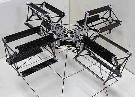
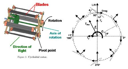
Fundamentally, a cyclocopter is similar to a helicopter in that it creates lift through rapidly moving airfoils. Unlike a helicopter, a cyclocopter's airfoils rotate around ahorizontalaxis, continually changing their pitch in order to generate thrust in one single direction:
It's certainly not a simple system, which is why this idea (which has been around in the form ofvarious prototypesfor nearly a century) only got off the ground to make a first untethered flight just recently, thanks to a lot of hard work from Moble Benedict and his team at the University of Maryland. They've been developing a cycloidal rotor system made of carbon fiber and titanium that's so far been applied to both a quad cyclocopter and a twin cyclocopter, and they've successfully gotten the two rotor version (with a supplemental tail rotor) into an untethered and more or less stable hover.
You're probably wondering what the advantages of such a complex system are, and luckily, there are a few. Primarily, it's suggested that a cyclocopter would be more efficient than a helicopter, able to generate more thrust for a given amount of power. It's also thought that cyclocopters will prove to be more maneuverable, since the thrust can be vectored very rapidly. On the downside, you've got the overall complexity of the system to deal with, and the weight of the rotors might cancel out any efficiency gains.
Almost all autopilots use PID algorythms in one way or another. Now there's a basic PID library in the standard Arduino software. Even better, here's a tutorial series from Brett Beuregard on how to use it!
In conjunction with the release of the newArduino PID LibraryI’ve decided to release this series of posts. The last library, while solid, didn’t really come with any code explanation. This time around the plan is to explain in great detail why the code is the way it is. I’m hoping this will be of use to two groups of people:
People directly interested in what’s going on inside the Arduino PID library will get a detailed explanation.
Anyone writing their own PID algorithm can take a look at how I did things and borrow whatever they like.
It’s going to be a tough slog, but I think I found a not-too-painful way to explain my code. I’m going to start with what I call “The Beginner’s PID.” I’ll then improve it step-by-step until we’re left with an efficient, robust pid algorithm.
I got my start in robotics with LEGO Mindstorms, so I'm glad to see continued sensor development there. Here's the latest: a 6DoF IMU from Dexter Industries. No word yet on what kind of software support it will have for sensor fusion.
Well the er9x TX and ardupilot combo is finished !
I use an Ardupilot and display it on the TX LCD on 10 screens (all backlight) No external things hanging out ! All internal in the 9x. Plus I have an autopilot with GPS, waypoints, stabilization, auto mode, takeoff/landing, and more to come.
Pic 1 is latitude/longitude ......great for lost plane Pic 2 stuff that goes in plane Pic 3 xBee 2way telemetry unit in er9x.
Looks really cool with 2 antennas too !
Put FPV video on plane and you have a UAV that costs less than a USED Reaper (if you could get one) Cost ??? about $300.00 Is YOUR plane worth it ?
I recently wrote my thesis on the topic of using feedback control to provide a vertical position autopilot for an RC helicopter. I used a Gaui EP100 on a test-rig to test the control techniques. The control theory has been designed so that it can be applied to a helicopter of any dimension/number of blades. It is presented in this 26 page document. I hope this can be of some use to someone!
The video below shows me performing some basic disturbance rejection tests.
4 Milk bottle with inside water , 1 bottle 1 kg of water.
The firmware is a custom revision of ArdupiratesNG32 , in the next week start to check the ACM 2.0.38 on MP32 all is ready for doing some flying test .
I'm working on the MultinoCopter project since 2 months. It is a 50x50mm size board with full compatible arduino pro mini architecture and 9DOF imu. I didnt share it because i have to finish the multicopter code before. Now it is working as a serial IMU for the computer based projects (calculating euler angles) and camera stabilizer.
Yesterday i tested the camera stabilization code on the 3 axis. The mount coming from a giant rc helicopter and it designed for Canon 7D.
Do you know that chip which goes on Arduino USB Host Shield and ADK boards? Yes, that's Max3421 from Maxim. And that other one which integrate some text based OSD boards? Hmmm... OK it is the Max7456 from Maxim too. Well, from now on, Maxim will be there on our buddy gyros too.
Maxim Integrated Products acquired SensorDynamics a Leading Specialist in MEMS and Wireless Semiconductor Products.
“Maxim is a recognized leader in analog integration, and this acquisition extends Maxim’s integration strategy by enabling us to fuse many types of sensors with our analog technology. The strategic integration of sensors, analog functions and low power wireless connectivity will allow us to deliver end to end mixed signal solutions that provide our customers with better performance, smaller form factors and lower system costs,” said Tunc Doluca, Maxim’s President and Chief Executive Officer. “The result will be a unique combination of technologies that will eventually enable a whole new generation of intelligent machines. We’re thrilled that SensorDynamics is joining us.”
This is my Quadcopter, a project born because of a passion hobby and a thesis research excuse. :P
Specificactions:
4 Outrunner Motors KD36-10XL of 810 [kv] and 24 [A] max.
4 ESC Turnigy Sentry 60 [A]
2 LiPoly Batt. Rhino 2250 [mAh]
4 Blades APC 12x3.8
1 Pair of Xbee 900 Pro
1 Arduino Mega (For first trials)
And for now, it flies without autonomus control, I've got "stability" control using four potentiometers for modifying the PWM for the ESC and trying to stabilize it that way. But now I'm working on using a 9 DOF IMU Stick from Sparkfun.com and trying to change the Arduino Mega for a Maple from LeafLabs but specially having trubble with this. Also want to use a BMP085 Pressure and Temperature sensor for simple environment information. Hope somene could help me on my way to finish this project which is in tha last stage of research. And from now on, publishing my new advances of this quad.
This was a real head scratcher for me, so hopefully this will help others. I have had this radio for 4 years now but never used it as it was so complicated. I decided to RTFM which honestly just confused me the futaba manuals have never been to my liking. I read manuals for a living and compared to some of the rubbish ones this is definitely worse.
I tried all of the other methods listed for Futaba and couldn’t get them to work mostly because there is no "Switch off" offset that I could find. So I couldn't get the P-Mix methods to work correctly.
First a few caveats: 1) I am doing this for the AC2 so I don't know how well it translates to APM. 2) Even the same make and model radio differs from the next so don't just follow the numbers I've input blindly, your values will be a little different. 3) I've included the button push sequence. Those who have a 9z will know that the buttons are labelled A through R. this takes you through those. They all start form the home screen.
4) Finally my 9ZHP has the WC II software which changes a few things so you might not be able to follow the button pushes.
Ok let’s start.
1) First set up a new model and set the type as aeroplane. Go to the servo display (SRV) under the system menu and check that there is no mixing and that all the channels move in the correct directions.
2) Reverse the Throttle Channel: All the Futaba radios I have used over the years have need the throttle channel reversed and this one is no different. Go to the model menu (MDL) then on to the Reversing section (REV) and change the throttle.
Button Push sequence: Home>P>B>J>G>P>N>R
3) Next set up channel 5 (GEAR) with a 2 position switch I chose Switch F (SWF). Go to the Model menu (MDL) then choose Function (FNC) and select your chosen switch.
Button Push Sequence: Home>P>B>K>I>P>M>J>N>R
4) Set up two flight conditions in addition to the default condition and assign switch A to change between the three of them. Go to the Model Menu (MDL) then on to the condition select menu (CSL) you will see that the first condition is D and can’t be changed select the second one and then change the switch to a three position switch I used switch A.Adjust so that it is ON in the middle position. Then do the same with condition 3 assigning switch A and this time make it ON in the lowest position.
5) Set up your ACM/APM and receiver and connect it to the computer using your USB Lead. From the mission planner open the terminal window. Once it is all up and connected type "test" you will see it go into the test menu type “pwm” and you will see the values for the PWM on each channel come streaming in. We are interested in CH5.
6) Now we are going to set the CH5 (GEAR) Adjustable function rate (AFR)...... (Don’t ask me who came up with these names???). Each AFR is tied to a flight condition so each time you change Switch A you get a new high and Low AFR this means we can have 2 positions per flight condition and with 3 conditions we have 6 positions in total. OK go to the Flight Condition menu (CND) then open the AFR screen. Change the channel to Gear (GEA). Now check that switch A is in the top most position and that switch f is in its rearmost position. Now while watching the pulse width on your screen change RATE A until the pulse width is 1165 (Mode 0) give or take 5. My radio needed 64% then change RATE B to give you 1815 (Mode 5). Note you will have to change SWF to forward position to see RATE B have an effect. My value was 54%. Now move switch A to the middle position and do the same for Flight condition 2 but this time adjust RATE A to 1295 (Mode 1) and RATE B to 1685 (Mode 4). My values were 40% and 30% respectively. Now move switch A to the lowest position and do the same for Flight condition 3 but this time adjust RATE A to 1425 (Mode 2) and RATE B to 1555 (Mode 3). My values were 17% and 7% respectively.
Now you should have all 6 modes. Starting with switch F in the rearward position and switch A in the topmost position, you are in mode 0 then moving switch A downward you should get 1 then 2. Then flip switch F forwards this should give you mode 3. Move switch A back to the mid position and you should get mode 4 and finally move A to the topmost position you get mode 5
Button Push Sequence: Home>O>B>G>B>I>(CHECK THAT SWA IS IN UP POSITION AND THAT SWF IS IN THE REAR POSITION)>C>(CHANGE VALUE USING F&G)>(CHANGE SWF TO FORWARD POSITION)>D>(CHANGE VALUE USING F&G)>(CHECK THAT SWA IS IN MIDDLE POSITION AND THAT SWF IS IN THE REAR POSITION)>C>(CHANGE VALUE USING F&G)>(CHANGE SWF TO FORWARD POSITION)>D>(CHANGE VALUE USING F&G)>(CHECK THAT SWA IS IN DOWN POSITION AND THAT SWF IS IN THE REAR POSITION)>C>(CHANGE VALUE USING F&G)>(CHANGE SWF TO FORWARD POSITION)>D>(CHANGE VALUE USING F&G)>N>R
When I first got interested in UAVs I took the advice of some of the forum members here and equipped myself with arduino based systems....but I'm a crazy engineer and this approach didn't last long before I had convinced myself I could make a better job of all this if I started from scratch...luckily I also managed to convince a friend of mine who specialises in electronics!
I'm an aeronautical and mechanical engineer, or I will be when I graduate! Resultantly I love all the spinning bits and the frames etc!
I've been a RC enthusiast for a while now and my original intention was to get a Radian glider flying autonomously, but just like the electronics, I swiftly became interested in a more exciting idea which I would have to custom build.
The result was the Talon airframe, which is the first in a series of aircraft with three goals in mind:
Vertical Take off and Landing (VTOL).
High Sprint Speed.
Long Loiter time in slow flight.
As you can see in the picture above, it is currently rather experimental and a little crude. The target of high speed flight has been completely ignored for now. Concessions to low speed loiter come in the form of modified Radian Glider wings and VTOL is achieved by wing and motor tilt.
I'll write more detailed posts about Talon on my website, www.universalair.co.uk - where the code will also be released open source.
It is controlled by the boards my friend has designed which we call "Forebrain" - the processor and "Seraphim" - the sensors.
Here is a brief video of a suspended test, as you can see, the pitch axis whilst hovering is the least damped and worst aerodynamically actuated so it has been hard work getting it stable, I'm currently running code verification on a quadcopter before returning to Talon.
Will probably post soon about the quadcopter too, looking forward to hearing any interesting comments/ ideas about the aircraft!
 I have to say that it looks quite nice too.