All Posts (14061)

Sort by

south bay blackhawk

Anyone see the blackhawk flying circuits over the south bay? Bet it was autonomous because it was over unpopulated areas, in line of sight of Mountain View, & flying an extremely boring mission.

Read more…
Developer
This is a rough/raw release of my ArduStation with tracking antenna support. In order to make it work you must calibrate your servo's range (pan 360 degrees, tilt 45 degrees). It uses your actual altitude and location against the altitude/position of your aircraft to accurately point your antenna. I guess the resolution is pretty good!What you need to do to make it work with ArduPilot:-Go inside the code an calibrate your sensors, using this line on the first tab://Servo Calibration!!!!Pan.attach(9,1000,1990);//PAN ServosTilt.attach(10,600,2150);//Tilt ElevatorThe second and third values are the min and max in milliseconds of the servos. (The first value is the Servo Pin Port)Then go to the definitions at the beginning and change these values. To activate them just change it for "1":#define TEST_PAN 0 //Test pan min and max (for calibration).#define TEST_SOUTH 0 //test south (the antenna will just point to south).#define TEST_TILT 0 //test the tilt max and min (for calibration).After you see your tracking antenna is working right, go to the flight field and point your antenna (in south test mode) to your true south... I chose south as a default because when you're between 1 and 360 degrees the antennas makes full rotations to jump from degree 1 to degree 360.You can download the lastest code here:ArduStation_V13.zip
Read more…

2nd Arduino adds 2-way Com with Ground

I wanted two way communication with my aircraft, but when the GPS is running, the Arduino board only has 1 side of its single serial port available, so I added another Arduino Mini to provide 2-way communication between my ground station and the aircraft.The additional board consists of a 5 volt Arduino Mini Pro, with a ATMega 328 chip running at 16 mHz, and a Spark Fun 5 volt carrier board for the XBee. That's it. I had to move my Gyro to this new board, cause I used I2c to link the main ArduPilot board with my new "com" board, and I2c uses the Analog Pins 4 & 5 for communication. (I had my gyro on analog 4&5)

It takes three wires to connect to the ArduPilot board - SDA, SCL and Ground. The two I2c wires go to Analog pins 4 and 5 on the ArduPilot board. Ground plugs into an open servo socket. I used a separate 7.4v lipo battery to power the new Arduino and the XBee. (the XBee 900 XSC draws 250 mah during transmission)

The code changes within ArduPilot were very minimal. I used the Wire Library for I2c. It's not efficient, but it's easy to use. It uses blocking reads, which means your code is sitting around waiting for the data to arrive back, instead of being able to go about your business until an interrupt tells you your data is ready. I'll improve this later.All of my downlink data (data going to the ground station) is isolated within the print_data() function - so making the changes was easy. I used the PString library to mimic the Serial.print calls, so code that used to look like:Serial.print(",CRS:");Serial.print(ground_course);Serial.print (",SPD:");Serial.print(ground_speed);Serial.print(",CRT:");Serial.print(climb_rate);Now looks like:theStr.print(",CRS:");theStr.print(ground_course);theStr.print (",SPD:");theStr.print(ground_speed);theStr.print(",CRT:");theStr.print(climb_rate);Wire.beginTransmission(4); // transmit to our I2c slave Arduino (ID=4)Wire.send(theStr);Wire.endTransmission();The slave Arduino takes all I2c data it receives from the master and transmits it out it's serial port to the XBee where it continues thru space to the ground station.// This is the interrupt routine in the slave Arduino that gets called every time// the master sends out some data.void master_has_sent_us_data (int howMuch){byte slen=0;while (Wire.available() > 0){RxBuffer[slen] = Wire.receive();if (slen < MAX_BUF_INDEX) slen++;}RxBuffer[slen] = 0; // terminating zero for c-stringSerial.println(RxBuffer); // Send to Ground Station via XBee}// -------------------Reading the Gyro is easy. It's actually an analog gyro, but now the main software reads it like it's an I2c gyro. Every 20ms the main loop calls:Wire.requestFrom(4, 4); // request 4 bytes from our slave device #4if (Wire.available() >= 4){gyro = (Wire.receive() << 8) + Wire.receive(); // read 2 bytes as an IntvRef = (Wire.receive() << 8) + Wire.receive();}// -----So for about $40, and a couple hours wiring, I get another serial port, 4 more analog ports (2 of the 6 are used for I2c) 13 more digital lines, and a bunch of horsepower (that pretty much goes un-used) But it's cool - and I really wanted the two way com between the aircraft and the ground. Now I have it. Cheers.
Read more…

5th or AUX RX Channel

Im looking to start a UAV project based on the Dynam Hawk Sky which I had posted a day or so back. I got a lot of comments on the radio system saying its junk, and cannot be used because it does not have a 5th or AUX channel for the AutoPilot. As an 18 year old working at RadioShack, I cant really afford a new radio system let alone the components for AutoPilot, but I figure if I put a little money away every check or so I could have myself a UAV built up before Christmas. (An early Christmas present for myself if you will. c=) So I will be using the stock radio gear. Though its advertised as 35mhz, I got a confirmation from a recent buyer of the plane that it is 72mhz as presumed by others in my last post.My question is:Could i Sacrifice my Rudder's channel on the RX for use in the AutoPiolot beings that the plane im using has ailerons?and maybe even mod my TX to disconnect the rudder's control input, drill a small hole and wire it to a simple toggle switch?Any help would be appreciated.-Mike
Read more…
3D Robotics

Using the HobbyKing RC gear

If you chose the Blimpduino RC option, your kit will come with a HobbyKing 2.4 Ghz RC transmitter and receiver. It won't, however, come with instructions! (Blame HobbyKing for that). No fear, here's what you need to know.
Like all 2.4Ghz RC systems, you need to bind the transmitter to the receiver before you use it. Here's how to do it:

1. Batteries in transmitter, switch off.
2. Put the bind plug in the BAT slot on the receiver.
3. Connect an ESC (with battery attached) to one of the channels. Black line (-) goes to the outside. You will see a red LED blinking. (You might have to look from the side; it's hard to see)
4. Push and hold down the bind button on the transmitter while switching on. Keep the bind button held down until the red LED stops blinking.
5. Remove the bind plug and turn off the power. When you turn it out again with the transmitter on, thered LED should be solid.

Note that the Receiver comes with a little satellite antenna thing. Remove it--you won't need it indoors. Also, please note that the RC equipment is powered by the Blimpduino board, via the cables. Do not plug the battery straight into the receiver.

Here's the full manual:
Part One
Part Two
Part Three
Read more…
3D Robotics

DIY Drones store stock status

Just a quick update on the availability of some popular items: --The XYX Thermopile sensors are back in stock [Sigh. Immediately sold out again. Give another week to replenish] --The uBlox 5 modules and adapters will be in stock in about a week. --Blimpduino is back in stock. If you want the version with RC gear, it's looking like an Oct 26th availability. --ArduIMU: in stock in about a week. --ArduPilot Shield: in stock in about a week
Read more…
Moderator

2.4 Xbee in a box

As I fly lots of airframes I thought it might be a good idea to have a standalone tracker, so I put an Xbee in a box with a EM406 and its own battery. Very simple to setup using the meshing Xbees, makes me wonder if I added another and put it on a pole at a distance if it would not make a simple repeater, does anybody know.Having its own power means that it will continue working should there be any issues with the airframes power, that does mean quite a bit of weight though.So far I have only completed walking tests and the range appears to be about 350m, if that gets upto 500 when one of them is in the air then I will be happy it will do what I need.After following these instructions http://www.humboldt.edu/~cm19/XBee%20setup.pdf to setup the two Xbees.I found Earth Bridge to listen to the GPS and interface with Google Earth.

Here's the walk test

Read more…

Flight tests with the UAV DevBoard

After my last UAV project went up in flames (literally!) I’ve shifted gears and designed a dedicated autopilot (AP) test vehicle. She is a tailless plane with removable wings for transportation and has plenty of room in the fuselage with easy access.

For the autopilot, I’m using Bill’s UAV DevBoard with a modified AileronAssist code for handling the elevons. This modification is a work in progress by Ben Levitt and he is including a lot of great features. You can check out the latest versions of the code here. The tailless had her first autonomous flights this weekend and I’ll be posting all of the flight logs on this blog. So far, I’m really pleased with the AP’s performance. Not only does the DevBoard and software perform well, but Bill also provides a wealth of information on the theory of his methods as well as the “how to” to get the hardware and software installed and running. I know this is beginning to sound like a commercial for Bill’s stuff but if you do a search on this website, you’ll find nothing but praise for Bill and his accomplishments. And to top it all off, he’s always willing to immediately chime in and help whoever asks for assistance.

Read more…

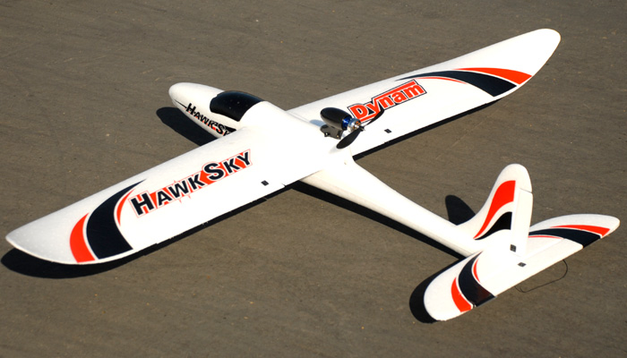
60A-DY8925-HawkSky-1.jpg

After looking at the suggested planes for use as a UAV, I noticed there not all that cheap.The plane considered for a UAV builder "on a budget" was still something like $110.00 without any electronics!I know the Easy Star is a pretty popular model in use with UAV construction, and even that is bumping $200.00 without a brushless motor.I came across the Dynam Hawk Sky and saw for $119.00 you get a plane simular to the body style of the easy star, a brushless and li-poly battery upgrade, and everything needed to fly out of the box.so my question pretty much is,first of all, does anyone own this plane?what is your guy's opinions on this plane?do you think it will get the job done?-Mike
Read more…
3D Robotics
Free video streaming by Ustream Tonight (Sunday) we'll do our fifth podcast, which everyone here is welcome to participate in by listening to the chat live above and commenting and asking questions via the DIY Drones chat function. We'll be starting at 9:00 PM PST and will probably go about 40 minutes. This week we'll by joined by Ryan Beall, talking about his homebrew IMU autopilot Asteryx. Other themes will include --Launch of the DIY Drones Workspace and the teams that are underway --The conclusion of the Outback Challenge contest --The flat-gyro era arrives --Favorite blogs posts of the week --And whatever other cool stuff comes up!
Read more…

Adding Gyro Smooths out Turns

While flight testing my Magpie and ArduPilot, I was having a problem with over-shoot during Way Point Navigation. After hitting the way point, the aircraft would start turning towards the next way point, and then continue turning until way past the bearing to the next way point, requiring the aircraft to make a sweeping s-turn to get back on track towards the next way point.

I suspected a number of things... the directional bearing data the aircraft uses comes from the GPS "Ground Course" data. It has no idea which direction you're actually pointing, it can only tell you the bearing between where you are now, and where you were a little while ago. I'm using the EM406 GPS, and there's a little lag in what it tells you your course is, as it tries to integrate, and smooth the data it's receiving. In addition, while my aircraft is in a high banking turn, it's actually pointing "ahead" of where the direction vector says it is, and, my GPS only puts out new data once per second, so the current course data available to the Nav functions is old, and the aircraft easily gets pointed way ahead of where I want it to.So... I did a couple things. I added code to calculate my own CMG (course made good) that didn't filter or smooth the data so I'd have better data quicker, I added a Gyro to update my current bearing based on rate of rotation during a turn, and I added some code to compensate for high bank turns, that essentially add some offset to the current heading based on how much the aircraft is banking.Works Great. The Gyro is sampled every 20 ms, and updates the variable gyroHeading based on rate of rotation. Every 200 ms I set the update flag so the nav routines think there's new data, and re-evaluate the roll set point based on the updated heading provided by gyroHeading. Every time I get new GPS data (once per second) I re-calc my own version of CMG by calc'ing the bearing BACK to where we were 1 second ago, and setting gyroHeading to this new course. That way, gyro drift is minimized (it only has 1 second to get in trouble) and I really only need the gyro during high bank turns, where the aircraft's course is changing quickly, and I'm only getting GPS data once per second. This gives the nav function 5 updates per second on the "true" nature of the quickly changing course of the aircraft, and the PID functions then do a much better job of calculating the roll set point needed to "round the mark" smoothly.

// --------------------------------------------------------------------------------------------------// adjust the heading if we're banking hardint heading_roll_compensation(){int rollAmt = get_roll();if (abs(rollAmt) < 16) return 0; // don't adjust unless banking hardreturn (rollAmt/2);}// --------------------------------------------------------------------------------------------------// Calc our own Course Made Good - use as Gyro Referencevoid calc_our_CMG(){static float prevLat=0;static float prevLon=0;if (calc_dist(prevLat, prevLon, lat, lon) > 1){ourCMG = calc_bearing(prevLat, prevLon, lat, lon) + heading_roll_compensation();if (ourCMG > 360.0) ourCMG -= 360.0;if (ourCMG < 0) ourCMG += 360.0;prevLat = lat;prevLon = lon;gyroHeading = ourCMG;}}// --------------------------------------------------------------------------------------------------The code is then used within the function navigation():wp_bearing = calc_bearing(lat, lon, wp_current_lat, wp_current_lon);calc_our_CMG();roll_set_point = calc_roll(heading_error(wp_bearing, gyroHeading), dt_t);Note that calc_our_CMG() will NOT update gyroHeading every time thru, only when it gets new GPS data that puts us at least 1 meter away from our previous position (usually every second) In between, the gyro will have been updating gyroHeading 5 times per second so the nav routines can respond quick during the turn.The code below supports the Gyro. Init_Gyro_Bias() is called during init - NO MOTION.The main routine sample_gyro_data() is called each time thru the main loop.// ---------------------------------------------------------------------------------------------------------------------------// Called from Main Loop to sample gyro data & update gyroHeading.// Sample the analog data from the Gyro about 2,000 times per second.// call the Update Heading routine only every 20ms// smooth the over-sampled analog lines.void sample_gyro_data(){static unsigned long gyroTimer=0;static unsigned int gyroCounter = 0;unsigned long dt;analog4 = (analog4 + analogRead(4)) >> 1; // sample Analog inputs every time thruanalog5 = (analog5 + analogRead(5)) >> 1; // analog 4 & 5 are for the Gyrodt = millis() - gyroTimer;if (dt > 50) dt = 50;if (dt > 20) {update_gyro_heading(dt);gyroTimer = millis();gyroCounter++;if (gyroCounter > 10) {data_update_event |= 1; // update rudder info 5 times a secondgyroCounter = 0;}}}// -----------------------------------------------------------------------------------------------------------------------------// rate of gyro at full swing = 150 degrees per second// this should be called every 20ms -> 50 times per second// dt is in milli-secondsvoid update_gyro_heading(int dt){int gData;float gyroDelta;gData = (analog4 - analog5) - gyroBias; // range is now -512 ... 0 ... 512gyroDelta = (float)(gData) / 512.0; // range is now -1.0 ... 0 ... 1.0gyroDelta = gyroDelta * 150.0 * (float)(dt / 1000.0);gyroHeading += gyroDelta;if (gyroHeading > 360.0) gyroHeading -= 360.0;if (gyroHeading < 0.0) gyroHeading += 360.0;}// ---------------------------------------------------------------------------------------------------------------------------// gyroBias = reading of gyro at rest. So we know the zero point.// called at Init time gyroBias = init_gyro_bias();int init_gyro_bias(){int n;int theBias;analog4 = analogRead(4); // sample Analog input for gyro rateanalog5 = analogRead(5); // 2.5v voltage reference = 512theBias = analog4 - analog5;for (n=0; n<50; n++){analog4 = (analog4 + analogRead(4)) >> 1; // range 0..1023analog5 = (analog5 + analogRead(5)) >> 1;theBias = (theBias + (analog4-analog5)) / 2; // signed value -512..0..511}return theBias;}// ---------------------------------------------------------------------------------------------------------------------------
Read more…
Developer

XFPilot with Navigation

I've been working on this the last two weeks and I finally today did a successful walking navigation using the software. It's an extension of the last version I posted which now includes navigation (EM406 only). It's still a work in progress and I'll have it in the air soon, but until then I thought I'd share.The whole reason behind making this was to create something custom fit for my FPV setup. I'm also interested in trying alternate styles of navigation algorithms which I can now do, and test them with my ground station. All the code is custom written except for the GPS parsing algorithm which was only changed slightly to use Longs instead of Floats. (I'm doing a lot more calculations per second than the current Ardupilot, so I wanted to stay away from Floats.)I'm also reading the throttle input instead of using a 'remove before fly' jumper which frees an Arduino pin for other uses such as Lights or my audio based telemetry.The nav algorithm is pretty simple but it will keep the plane on track during high winds and I use simulation to predict when I'll reach a waypoint and how much I'm turning based on the IR readings. I'll be adding an airspeed sensor soon which will greatly add to the accuracy of the sim and give it throttle control.Here is a copy of the progress and a Flash base station. There are a bunch more features and details in the code and more coming soon. Feedback is welcome, and a special thanks to everyone who wrote the Ardupilot code. I've learned an enormous amount from it.JasonSource Files

Read more…

Need help: GPS position hold algorithm?

Hi all,I'm just wondering how can we perform a position hold (within 10-20 cm, just like microdrone MD4-200 did ) with a GPS and IMU because I know that the accuracy of normal GPS is aroung 2m and can not achieve up to few cm level if we dont have DGPS. So I'm thinking of a Kalman fusion between GPS and IMU to give a more accuracy in position ? I'm not so clear about that, it has made me confused for a long timeThat's why I post this entry to get your inputAny idea are appriciated and welcome.I forget to post a link to you guy for easy imagination of GPS position hold.http://microdrones.com/en_mc_videos.phpthen looking for a video name "flight-performance md4-200, part 3", this is what it called "GPS positon hold"
Read more…

Airspeed

Now onto trying to get the differential pressure sensor to do... something. I have the Ardupilot Shield alone with both 3.3v and 5v attached. Analog 3 on the Shield is connected to analog 0 on an Atmega328. Took some trial and error to get the code to read something meaningful (I'm new to this, obviously), and after that was on to road testing. I got the pitot tube from an R/C website, but don't remember which. Here's some redneck engineering at its finest:

/yes, that's masking tape (duct leaves residue) and a stickLiving in the desert, it was windy today. About 25mph with 33mph gusts. Fortunately it was traveling due east, and all the roads are N-S-E-W. So I did a few trials east and west (head and downwind) at the same velocity, then the same thing for north and south (crosswind). I played around with the data for a little bit, and found that the best results came from averaging each run, and then splitting the difference with its opposite. Came up with this graph of results:

Since there was a significant beta with respect to the airflow on the north/south runs, you can see that the pressure difference is less. Makes sense to me at least. So for the fit, I chose the headwind/downwind curve. Something I've noticed about real aircraft (analog and digital birds), you need about 40kts to get a decent airspeed. Same applies to this model. Here's my code:int analogPin = 0;int pressure;float velocity;void setup(){Serial.begin(9600);}void loop(){pressure = analogRead(analogPin);velocity = 2.15314 * (float)pressure - 509.48572;if (velocity < 40){velocity = 0;}Serial.print("Counts: ");Serial.print(pressure);Serial.print(", velocity est: ");Serial.print(velocity);Serial.println("mph");delay (1000);}Now the only thing remaining is to be able to read the GPS data, put it into an algorithm and then I'll be able to calculate the wind speed and direction while the aircraft is flying (one of my primary goals for this system). But considering what I've learned today, higher velocity will equate to more accurate wind speed measurements, so I'll have to account for this when building the airframe. Also, probably going to go out and repeat this test when there's no wind out.
Read more…

Easy to Build Ground Station

I've been tuning the GPS portion of my ArduPilot / Magpie airframe combination, and put together this flight data recorder to save the results of the flights without having to take a laptop out to the field.The data recorder consists of a Spark Fun Data Recorder, an XBee radio modem, and a battery. The Data Recorder takes a serial stream at 9600 baud, and records it to a SD data card as a text file.The Spark Fun card takes un-regulated power in (my 6v battery), regulates it, an provides the regulated 3.2v power required for the XBee. (very simple) Just 3 wires between the XBee and the Data Recorder, V+, Gnd, and DataOut (XBee->Recorder)

I used a 4 cell battery case from Radio Shack for power - it sits on the back of a bread board used to hold everything together. Very easy. Thanks Spark Fun for making such amazing little products.The aircraft has a XBee Pro 900 modem sending out 1 line of flight data every 300 ms. I capture it with my portable download link to an SD data card that I copy to my computer at home after the flight. The Spark Fun Data Recorder saves the data as a simple text file, that I post-process into a KML file for Google Earth.|-- AP Mode:1,GPS:0,Mir:189,CH1:-2,CH2:-1,IMU:321.74,CMG:306,GHD:301.77,CRS:319.61,***|-1 LAT:36956188,LON:-122063904,ASL:34.76,ALT:34,ALH:29,***|-2 WPN:2,BER:257,DST:54,CRS:317.06,SPD:23.57,CRT:0.30,WPa:125,***|-3 ASP:0,RLL:-20,PCH:-5,THH:30,rSv:7,pSv:10,rSp:-31,pSp:5,tSp:85,***|-4 GYRO:4,Rate:428,vRef:513,Bias:-89,***|-- AP Mode:1,GPS:0,Mir:189,CH1:1,CH2:0,IMU:318.86,CMG:305,GHD:300.63,CRS:310.88,***|-1 LAT:36956340,LON:-122064112,ASL:35.76,ALT:35,ALH:29,***|-2 WPN:2,BER:230,DST:45,CRS:305.32,SPD:24.04,CRT:0.00,WPa:125,***|-3 ASP:0,RLL:-44,PCH:-7,THH:30,rSv:10,pSv:11,rSp:-40,pSp:5,tSp:85,***|-4 GYRO:54,Rate:478,vRef:513,Bias:-89,***|-- AP Mode:1,GPS:0,Mir:192,CH1:0,CH2:-1,IMU:310.09,CMG:279,GHD:278.19,CRS:297.76,***|-1 LAT:36956444,LON:-122064368,ASL:36.46,ALT:36,ALH:29,***|-2 WPN:2,BER:196,DST:42,CRS:291.87,SPD:26.01,CRT:0.40,WPa:125,***|-3 ASP:0,RLL:-44,PCH:0,THH:30,rSv:11,pSv:2,rSp:-36,pSp:5,tSp:85,***|-4 GYRO:82,Rate:507,vRef:514,Bias:-89,***|-- AP Mode:1,GPS:0,Mir:192,CH1:0,CH2:0,IMU:297.90,CMG:257,GHD:259.03,CRS:284.54,***|-1 LAT:36956468,LON:-122064512,ASL:36.96,ALT:36,ALH:29,***|-2 WPN:2,BER:164,DST:45,CRS:280.27,SPD:24.76,CRT:0.20,WPa:125,***|-3 ASP:0,RLL:-45,PCH:-10,THH:30,rSv:8,pSv:13,rSp:-45,pSp:5,tSp:85,***|-4 GYRO:9,Rate:433,vRef:513,Bias:-89,***|-- AP Mode:1,GPS:0,Mir:192,CH1:0,CH2:0,IMU:285.74,CMG:239,GHD:238.06,CRS:275.35,***|-1 LAT:36956460,LON:-122064768,ASL:37.16,ALT:37,ALH:29,***|-2 WPN:2,BER:137,DST:46,CRS:264.31,SPD:18.75,CRT:0.70,WPa:125,***|-3 ASP:0,RLL:-37,PCH:-8,THH:30,rSv:10,pSv:12,rSp:-34,pSp:5,tSp:85,***|-4 GYRO:46,Rate:471,vRef:514,Bias:-89,***// ---------------I put what-ever I want in the print_data() function of ArduPilot, and it gets copied to the output stream.After the flight, I post-process the data file into a KML for Google Earth, so I can evaluate the results of the latest code changes.

Read more…

Compass, Baro Alt, and Temp Code

If anyone's interested, here's the code I used, slightly modified and spliced from the internet. This is for the SCP1000-D01, with my temperature running about 35 degrees F hot which for now I'm attributing to the heating from the amperage:// define spi bus pins#define SLAVESELECT 10 //CSB#define SPICLOCK 13 //SCK#define DATAOUT 11 //MOSI#define DATAIN 12 //MISO#define UBLB(a,b) ( ( (a) << 8) | (b) )#define UBLB19(a,b) ( ( (a) << 16 ) | (b) )//Addresses#define REVID 0x00 //ASIC Revision Number#define OPSTATUS 0x04 //Operation Status#define STATUS 0x07 //ASIC Status#define START 0x0A //Constant Readings#define PRESSURE 0x1F //Pressure 3 MSB#define PRESSURE_LSB 0x20 //Pressure 16 LSB#define TEMP 0x21 //16 bit tempchar rev_in_byte;int temp_in;unsigned long pressure_lsb;unsigned long pressure_msb;unsigned long temp_pressure;unsigned long pressure;float altitude;void setup(){byte clr;pinMode(DATAOUT, OUTPUT);pinMode(DATAIN, INPUT);pinMode(SPICLOCK,OUTPUT);pinMode(SLAVESELECT,OUTPUT);digitalWrite(SLAVESELECT,HIGH); //disable deviceSPCR = B01010011; //MPIE=0, SPE=1 (on), DORD=0 (MSB first), MSTR=1 (master), CPOL=0 (clock idle when low), CPHA=0 (samples MOSI on rising edge), SPR1=0 & SPR0=0 (500kHz)clr=SPSR;clr=SPDR;delay(10);Serial.begin(9600);delay(500);Serial.println("Initialize High Speed Constant Reading Mode");write_register(0x03,0x09);}void loop(){rev_in_byte = read_register(REVID);pressure_msb = read_register(PRESSURE);pressure_msb &= B00000111;pressure_lsb = read_register16(PRESSURE_LSB);pressure_lsb &= 0x0000FFFF;pressure = UBLB19(pressure_msb, pressure_lsb);pressure /= 4;altitude = (1 - pow((float)pressure/101325,0.19025515825))*(288.15/0.00199074074);Serial.print("Altitude ft [");Serial.print(altitude);Serial.println("]");temp_in = read_register16(TEMP);temp_in = temp_in / 20;temp_in = 1.8 * temp_in - 3;Serial.print("TEMP F [");Serial.print(temp_in , DEC);Serial.println("]");delay(1500);}char spi_transfer(volatile char data){SPDR = data; // Start the transmissionwhile (!(SPSR & (1<<SPIF))) // Wait for the end of the transmission{};return SPDR; // return the received byte}char read_register(char register_name){char in_byte;register_name <<= 2;register_name &= B11111100; //Read commanddigitalWrite(SLAVESELECT,LOW); //Select SPI Devicespi_transfer(register_name); //Write byte to devicein_byte = spi_transfer(0x00); //Send nothing, but we should get back the register valuedigitalWrite(SLAVESELECT,HIGH);delay(10);return(in_byte);}float read_register16(char register_name){byte in_byte1;byte in_byte2;float in_word;register_name <<= 2;register_name &= B11111100; //Read commanddigitalWrite(SLAVESELECT,LOW); //Select SPI Devicespi_transfer(register_name); //Write byte to devicein_byte1 = spi_transfer(0x00);in_byte2 = spi_transfer(0x00);digitalWrite(SLAVESELECT,HIGH);in_word = UBLB(in_byte1,in_byte2);return(in_word);}void write_register(char register_name, char register_value){register_name <<= 2;register_name |= B00000010; //Write commanddigitalWrite(SLAVESELECT,LOW); //Select SPI devicespi_transfer(register_name); //Send register locationspi_transfer(register_value); //Send value to record into registerdigitalWrite(SLAVESELECT,HIGH);}/-------------------------------------------------------------------------------------------------------------------------------This is the code I used to get a decent compass heading. There's a lot of extra fluff in this code, and its not modified at all:#include#includeint magReading = 0;int XmagValue = 0;int YmagValue = 0;int Azimuth = 0;void setup(){Serial.begin(9600);Wire.begin();}void magRead(int outputMode){// int HMC6352Address = 0x42;// Shift the device's documented slave address (0x42) 1 bit right// This compensates for how the TWI library only wants the// 7 most significant bits (with the high bit padded with 0)// slaveAddress = HMC6352Address >> 1; // This results in 0x21 as the address to pass to TWIint slaveAddress = 0x21; // This is calculated from HMC6352's address, see comments aboveint ramDelay = 100; // us, delay between a RAM write command and its effect, at least 70usint getDelay = 10; // ms, delay between a get data command and its effect, at least 6msbyte magData[2];int i;switch (outputMode){case 0:Wire.beginTransmission(slaveAddress);Wire.send(0x47); // Write to RAM commandWire.send(0x4E); // Output Mode control byte addressWire.send(0x00); // 0x00 for Heading modeWire.endTransmission();break;case 1:Wire.beginTransmission(slaveAddress);Wire.send(0x47); // Write to RAM commandWire.send(0x4E); // Output Mode control byte addressWire.send(0x03); // 0x03 for Magnetometer X modeWire.endTransmission();break;case 2:Wire.beginTransmission(slaveAddress);Wire.send(0x47); // Write to RAM commandWire.send(0x4E); // Output Mode control byte addressWire.send(0x04); // 0x04 for Magnetometer Y modeWire.endTransmission();break;default:Wire.beginTransmission(slaveAddress);Wire.send(0x47); // Write to RAM commandWire.send(0x4E); // Output Mode control byte addressWire.send(0x00); // default to Heading modeWire.endTransmission();}delayMicroseconds(ramDelay); // RAM write needs 70 microseconds to respondWire.beginTransmission(slaveAddress);Wire.send("A"); // The "Get Data" commandWire.endTransmission();delay(getDelay); // Get Data needs 6 milliseconds to respondWire.requestFrom(slaveAddress, 2); // Request the 2 byte data (MSB comes first)i = 0;while(Wire.available() && i < 2){magData[i] = Wire.receive();i++;}magReading = magData[0]*256 + magData[1];}void loop(){magRead(0);Azimuth = magReading;magRead(1);XmagValue = magReading;magRead(2);YmagValue = magReading;Serial.print("Mag X: ");Serial.print(XmagValue);Serial.print(" Mag Y: ");Serial.print(YmagValue);Serial.print(" Azimuth: ");Serial.print(-int(atan2(YmagValue,XmagValue)*57));Serial.print(" degrees ");Serial.print(int(Azimuth/10));Serial.println(" degrees ");delay(500);}
Read more…