All Posts (14054)
Sort by
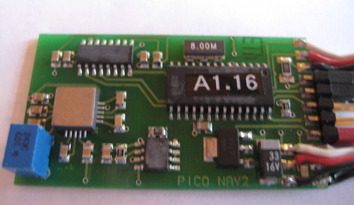 PicoPilot NA bottom:
 ALT3E top:
 ALT3E bottom:
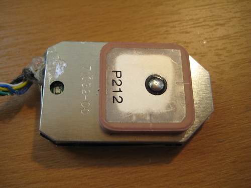
 GPS module outside (this is just a standard Holux GPS module):
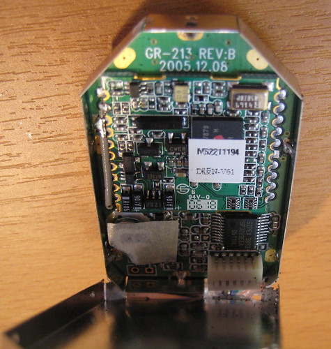
 The Holux GPS module inside:
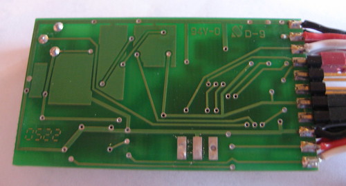
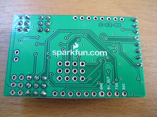
 To give you an idea how basic these PCBs are, here's the PicoPilot bottom and the AttoPilot and ArduPilot bottoms side by side, ranked in increasing sophistication. Again, note the careful effort to maximize the ground planes (big light green areas) for noise reduction in ArduPilot and AttoPilot, and the minimal use in PicoPilot.
PicoPilot PCB bottom:
ArduPilot PCB bottom:
To give you an idea how basic these PCBs are, here's the PicoPilot bottom and the AttoPilot and ArduPilot bottoms side by side, ranked in increasing sophistication. Again, note the careful effort to maximize the ground planes (big light green areas) for noise reduction in ArduPilot and AttoPilot, and the minimal use in PicoPilot.
PicoPilot PCB bottom:
ArduPilot PCB bottom:
 AttoPilot PCB bottom:
FMA CoPilot thermopile sensor
Soldering breakout cable to dismantled FMA CoPilot
CoPilot with breakout cable
Locosys LS20031 GPS board with 4 pin male header
Plugging GPS board into turret
Adding some foam pad between GPS and CoPilot
Plugging CoPilot and inserting into turret
Turret back view with inserted devices
Turret side view
- 1.0: Just navigation and altitude hold (released 1/09)
- 2.0: Adds XY-sensor stabalization, EM406 only (released 3/09)
- 2.0.1: Adds Z sensor, ground station support (released 4/09)
- 2.1: Supports XY sensor in diagonal position, desktop setup utility (does not require Arduino IDE), throttle (if airspeed sensor/shield is connected). Due week of April 20th
- 2.2: Requires ArduPilot 328 board (current board upgraded to the Atmega328 chip; stay tuned for details). Supports any GPS, fully configurable for different airframes, new navigation modes. Due early May
- Shields: We will be releasing expansion boards (called "shields" in the Arduino world) that plug into the top of ArduPilot and add additional features and connectors. This first one just adds a differential pressure (airspeed) sensor, 3.3v power regulator, lots of handy ways to add other sensors and GPS modules, and a circuit that allows you to upload code without unplugging the GPS. The first board will be available in May.
- 3.0: ??? Additional sensors (speed, power). Maybe IMU support?
- ArduPilot Pro: new board based on Arduino Mega. IMU based. Winter 09
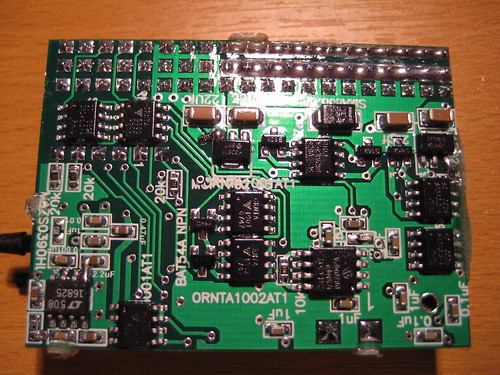
 And here's the bottom of the board. Click on this one, too, to find out what the components are:
