All Posts (11086)

Sort by
MR60

3689563422?profile=original

1 hour 20 minutes - APM 2.5 takes the world record for Multi-Copter Duration of Flight powered by a rechargeable battery. [note: other records exist for hover]

Flight Requirements


To discriminate flight from hover:

o Fly the following land distance -

  - While flying at an elevation greater than 2.5 meters

  - Cover 2.5 kilometers of land or more using 50 or fewer GPS points

  - Where two or more of the way points are more than 250 meters apart

o Gain the following altitude -

  - Accumulate elevations gains of 250 meters

  - Consisting of individual continuous elevation gain runs of 25 meters or more

  - Where every one second period, the elevation gain is positive

o Lands within 50 meters of Launch (to even out the use of wind)

o Without using thermals or wind lift affect to gain lift (flat ground, etc).

o Generation of flight logs (GPS, time, and elevations)

o Certified or scientific method (full disclosure of the ship design)

Actual Flight


- Distance covered 2.551 km

- Min elevation 2.5 meters

- Ended at start (within 6.1 meters)

- A hundred waypoints with two waypoints 283 meters apart

- Two climbs of 126 meters and 112 meters with a total of continuous 25+ meter climbs of 515 meters.

- Flight over ground that was void of thermals and updrafts (level ground +/- 10 meters)

- Wind was none to slight

- Temperature was approximately -2C to 1C from start to end of flight

Record Established:  +1hr and 20 minutes (81.43 minutes)

Date:  November, 26 2013, 10AM

Flight Documentation:

Earth views of the flight:  This is the top view.  It's an important perspective for understanding the video.  The man-cave is the L shaped building at the bottom where the ship was brought up to the 2.5 floor window where the camera was located.  The camera is pointed north from the man-cave to the turn-around point of the second way point (top of earth view).  The third way-point was mid-left on the route back to the man-cave.

3689563453?profile=original

The south-west side profile of the flight.

3689563339?profile=original

Elevation profiles of the flight:  From Mission Planner, showing BarAlt R

3689563435?profile=original

Data imported to Excel and plotted.

3689563466?profile=original

Videos of the flight:  are compiled from 2754 time-stamped Canon stills taken every 2 seconds.  At a video rate of 20Hz, the videos are 40x actual speed.  Sometimes the copter goes outside the FOV of the camera (had to trade between showing detail and scene area).  The white box that is the most visible part of the copter is the thermal blanket on the battery.  If you lose track of the copter, watch where I am and the copter is usually 5 to 120 meters up.

Stage 0:  Shows the flight prep and takeoff location about 1/3rd the way between the mancave and way point 2.

Stage 1:  The octa

- is launched

- brought to the man-cave viewing window

- sent north on it's first slow 120 meter climb reaching the apex about .3km away

- reaches the second way point (near the lone fir tree at the end of the field)

- turn SE over the orchard fan towards way point three

- turns SW back towards the mancave

http://youtu.be/5chgMCEKtfY

Stage 2:  The octa

- shows at the man-cave

- pauses near the launch site

- returns to way point 2

- returns to way point 3

- heads back to the man-cave

http://youtu.be/F7WMr7-1fek

Stage 3: The octa

- shows back at the man-cave

- begins second 100+ meter climb

- returns to launch

- lands

- return copter to mancave

http://youtu.be/fnXL8mOsCW0

Note:  Suggestions would be appreciated on a camera system that:
- works for 2 hours at -5C without needing a battery change
- can take 2 hours of video without needing a card change
- can produce a video that can be condensed and shared
- can be worn on your head

Flight Logs:  See attached or http://www.diydrones.com/forum/topics/world-record-for-duration-of-flight?xg_source=activity&id=705844%3ATopic%3A1484014&page=1#comments

o 2013-11-26 11-41 187.kmz (earth view logs) real-time generated by APM

o 2013-11-26 11-41 187.log (gps and elevations) real-time generated by APM

o 2013-11-26 11-41 187.log.gpx

Certification:  Scientific method chosen where full disclosure of the ship architecture and flight conditions can be replicated. 

Multi-Copter Design

- Octa

- A novel rotor layout to demonstrate the flexibility of APM 2.5 (a regular quad is likely the most efficient for duration)

- A rotor layout that can be adapted for camera use (open front and rear)

- Thus, two connected side-by-side + oriented quads with 6 rotors up + 2 rotors down

3689563510?profile=original

Ship material list and weights were as follows:

3689563535?profile=original

ESCs are stripped of all insulation, painted with silicone, and put in the prop intake to cool.

The battery, 40 Panasonic Li-Ion combined into a 4S10P, had to be wrapped in PVDF foam (made prop clearance a bit fun; PVDF is a nontoxic fire certified foam) since it was -2C out (significant weight gain).  Even with the foam, the battery only produced about 80% of what it should in the summer.

3689563491?profile=original

Spot welded serial connection for the batteries.

3689563656?profile=original

Construction process: followed the blogs on carbon tube construction using braided carbon composite tubes, aerospace adhesive, and zip ties.  See following links.

- http://www.diydrones.com/group/arducopterusergroup/forum/topics/building-copters-with-round-tubes-stronger-lighter-easier-to

- http://www.diydrones.com/forum/topics/build-your-own-copter-part-ii

Modification to APM Code:  APM is easily customize for any multi-copter rotor layout.  Documentation is available to explain the process.  The code below replaced the code for a V ("variant") octa.  The motors were numbered 1 to 8 going from left to right and then fore to aft.

        add_motor_raw(AP_MOTORS_MOT_1,  0.691, 0.522,  1.000, 1);
        add_motor_raw(AP_MOTORS_MOT_2, -0.691, 0.522, -1.000, 2);
        add_motor_raw(AP_MOTORS_MOT_3,  1.000, 0.000, -1.000, 3);
        add_motor_raw(AP_MOTORS_MOT_4,  0.382, 0.000, -1.000, 4);
        add_motor_raw(AP_MOTORS_MOT_5, -0.382, 0.000,  1.000, 5);
        add_motor_raw(AP_MOTORS_MOT_6, -1.000, 0.000,  1.000, 6);
        add_motor_raw(AP_MOTORS_MOT_7,  0.691,-0.522,  1.000, 7);
        add_motor_raw(AP_MOTORS_MOT_8, -0.691,-0.522, -1.000, 8);

Credits


o APM Development team

o Forrest Frantz (integration engineering, test, and pilot)

o James Frantz (electrical consulting and Scottsdale Foamie club)

o Leonard (math model)

o Hugues (motor suggestion)

o 3DR, T-Motor Company, Helibatics, SimonK, HobbyKing, Panasonic

o cptfrazz for setting such a high bar and use of Li-Ion

Purpose of the Record & the Challenge to Others

Please participate in the advancement of multi-copter technology by taking on the challenge of beating this world record. All that some of us ask is full disclosure of the ship so everyone can advance.  Multi-copters can be applied to many fields: inspection, conservation, and rescue to mention a few.  The faster we advance the technology, the more this amazing technology will be used, the more benefit society will accrue, and the more lives that will be saved. 

Read more…
3D Robotics

The train stopped after the driver spotted the drone lying on the tracks.

Drone's-eye view: The train stopped after the driver spotted the drone lying on the tracks.

This guy was lucky to get his quadcopter back. Key sentence: "Mr Prescott, who was in Sydney as part of the support crew for US singer Rihanna's Australia tour, says he was testing new equipment on his drone when he lost control of it. He says he never intended for it to fly into the bridge."

From the Sydney Morning Herald. 

Extraordinary video has emerged of a quadrocopter crashing into the Sydney Harbour Bridge last month.

The drone was launched by British man Edward Prescott. When the vehicle collided with a bridge girder and landed on the train line, it sparked an investigation by police and air safety authorities.

An edited version of the video uploaded to YouTube by Mr Prescott shows that the drone's camera was rolling the entire time it flew through and then into the Harbour Bridge, landed on a railway line, was picked up by Sydney Trains crew, placed in the train and taken back to their office.

The reaction and comments of the rail staff are all recorded.

On-screen text says the flying machine went out of control because the camera mounting failed, but the drone tried to return to its starting point using GPS.

After it crashes on to the rail line on the western side of the bridge a train is seen pulling up.

Two rail workers are captured by the drone's camera.

Two rail workers are captured by the drone's camera.

The driver picks up the quadrocopter and reports on his radio: "It's an odd looking plane, it's got a red light flashing, I don't know whether it's a bomb or not."

Pulling up at a train station, he then hands it to a bemused Sydney Trains worker on the platform.

"That's a first... a model aeroplane that crashed on the bridge," he tells her.

"It was in the road of the train so I jumped down and grabbed it."

After a brief stay on a platform office desk, the drone is given to another Sydney Trains worker who takes it to another office.

"It's got one camera lens. And it's flashing, like it's red now," the worker says, peering straight into the camera's lens.

He's then seen taking photos of the drone while his curious colleagues look on.

Mr Prescott, who was in Sydney as part of the support crew for US singer Rihanna's Australia tour, says he was testing new equipment on his drone when he lost control of it. He says he never intended for it to fly into the bridge.

Thinking his drone was lost to the harbour, it was not until he read about a "mystery drone" in the news that he realised what had happened.

"Imagine my surprise when the results of the internet search came back with a plethora of media sites from around the world carrying a story about a 'mystery drone', counter-terrorism investigation and a police hunt for the owner.

"Needless to say I contacted the aviation authorities and Sydney police immediately," he says.

A spokesman for NSW Police said the matter was investigated and deemed not suspicious.

He said that the police team managing the International Fleet Review, which started the next day and which included counter terrorism officers, were notified but that it was handled by police transport command.

The Civil Aviation Safety Authority completed a review of the incident but has yet to decide what action, if any, to take.

At the video's end, Mr Prescott writes in the credits:

"Special thanks to a level-headed NSW Police for returning my property.

"Peculiar how things turn out..."


Read more…
MR60

3689560310?profile=original

Some of you might remember a previous blog post last summer about my trainer 3DR quad going into the trees.

As a result I broke the 433Mhz telemetry module and antenna, as you can see on the picture above (SMA connector was ripped off the board).

This module was in my drawer since then. At the price of such a module I really did not want to throw it away.

On the other hand I wanted to try using bluetooth to connect my Nexus 7 tablet (with Droidplanner, thx Arthur!) to my X8 Octo. I use it for AP and I want to have my tablet and my TX radio together (not possible to frame a picture with a laptop and control the drone at the same time).

So here was an idea : Build a new antenna for the broken 3DR module, then connecting a bluetooth module to this 3DR module.

1-Let's start with the antenna built :

Due to the damage of the 3DR module, it was not possible to solder a new SMA connector. Plus I do not like very much the standard 433Mhz duck antennas. In these duck antennas we have a quarter wave antenna.

I decided to build a half-wave dipole antenna. Here are the parts to build it:

-A a regular servo lead (>200 mm long). Any other wire will do. it must be thin enough to be inserted in a plastic antenna protective tubing

-A 300 mm long (or longer) antenna plastic tubing like these:

3689560092?profile=original-Solder & iron

-Hot glue

-a Ruler (>30 cm)

Start cutting a 300mm long plastic tube. Mark its middle. Use a hot solder iron to melt a hole in the middle. This hole will be used to pass the servo wires through each half of the tube.

As it is diffciult to pass soft servo wires in such a tube, you can use a small rigid iron wire (take the one your wife uses to attach the roses in the garden...) on which end you solder the tip of the servo lead. Then pull the servo wire through the tube.

It should look like this afterwars:

3689560321?profile=originalAt this stage the two servo wires are extending out the tube.

We now need to cut each servo wire to measure exactly a quarter of a wavelength (i.e. total dipole length is a half wavelength):

Based on this relation between the speed of light (c), the radio wave frequency (v) , the wavelength is:

3689560281?profile=originalSo for a radio wave of 433Mhz, the lambda calculation gives (in MKSA standard units, sorry for inchies):

3689560342?profile=originalSo we have theoritically to cut the servo wires to have a total length of 34,62 cm.

HOWEVER, there is a bit of wire length extending outside the tube (to the 3DR module) AND

the plastic tubing contains carbon. Carbon is an electricity conductor. Therefore carbon based plastics have an impact on radio wave frequency tuning. A rule of thumb : the more plastic (carbon), the more the theoritical length should be shortened. I went for an horizontal length of 30 cm (+ about 1cm of wire outside of the tube, so a total length of 31 cm). 

Thus, take your ruler and measure 15 cm on each side of the hole (300 mm total length) and trim both ends.

Final step : solder the two wires on the 3DR module. At this stage we have to solder one servo lead (half of the antenna) to the ground, and the other servo lead (the other antenna half) to the antenna port of the module.

Be careful when soldering that the wires should never touch!

3689560286?profile=originalOn the picture, the red servo lead is soldered on the ground port of the 3DR module. The white servo lead is soldered on the antenna port.

Now it is time to check is this home made antenna is worth something. I compared two configurations as follows:

1-the 3DR module with its default duck (quarter wavelength) antenna (and a FTDI cable to the computer on which I'm running mission planner).

2-the 3DR module with this home made dipole (and a FTDI cable to the computer on which I'm running mission planner)

Of course the physical setup/relative positionning between the telemetry modules & antennas remains identical in both cases.

1-Chart with standard duck antenna: RSSI measured between [170-190]

3689560350?profile=original

2-Chart with home made dipole (half-wavelength) : RSSI measured  >=200

3689560358?profile=original The home made dipole wins !

(The second part on the bluetooth connection follows below)

Read more…

MAVProxy Workshop and Documentation

3689560069?profile=originalIn Canberra (Australia) we recently ran a "How to use MAVProxy" workshop at the MHV workspace. We had a dozen or so people turn up and we spent the afternoon going through the software and it's numerous modules.

For those who don't know about MAVProxy, it is a UAV ground control station (much like Mission Planner). The emphasis is on portability, stability and low use of system resources. It was the ground station software used by the CanberraUAV team in the 2012 Outback UAV Challenge.

By itself it runs on the console, but can be extended via modules which provide a (basic) GUI. It works on any Windows or Linux machine (via Python) and is compatible with any UAV using the MAVLink protocol, such as the APM and PX4/PIXHAWK.

The documentation for MAVProxy has recently been updated and can be found at http://tridge.github.io/MAVProxy/

Read more…
3D Robotics

New York Times on "drone journalism"

3689560257?profile=original

Good New York Times round-up of recent examples and some of the policy issues presented by "drone journalism". Excerpt:

The best way to film the destruction wrought by Typhoon Haiyan in Tacloban, the Philippines, said Lewis Whyld, a British photographer, was from the air.
But Mr. Whyld did not want to beg for a ride on a military helicopter, taking the space of much-needed aid. So he launched a drone into the skies above the city. In addition to shots that showed the scale of the damage, broadcast by CNN recently, his drone discovered two bodies that were later recovered by the authorities, he said in an interview.
“The newspaper was for still images,” said Mr. Whyld, who builds his own drones, “but the Internet is for this.”
Mr. Whyld, and CNN, are not alone in exploring the potential of drones. The Associated Press and News Corporation have used them to show the scale of large disasters. News Corporation has also used them to shoot sports in Australia. Sophisticated nature documentaries use them to get intimate shots of wildlife. Paparazzi use them to chase celebrities in Europe, and reports suggest they have been used to pursue celebrities in the United States, too.

...

Journalism programs, including those at the University of Missouri and the University of Nebraska, and the Tow Center for Digital Journalism at Columbia University, have started drone journalism courses. Columbia does not teach hands-on skills, but students at Missouri have used drones over the Missouri River for a report about hydraulic fracturing and over the prairie for a story about controlled burns. But in August, the F.A.A. ordered journalism schools to stop flights unless they obtained permission from the agency.

Read more…
100KM

The Techwing maiden flight

cpwing.jpg?w=900&width=300

Hello everyone!

A few months ago I recieved an email from Lorenz, main developer of the Pixhawk research project and  the PX4 autopilot. He urged me to create a small flying wing platform. Around 35 inch wing span and around 500 grams. capable of carrying a small camera like a gopro or canon s100.camera and an autopilot. I thought it sounded like an excellent idea. I could make it very portable and it could operate out of much more confined spaces then the techpod. 

So I got to work. After about 4 weeks of analyzing airfoils and reiterating designs I finally came up with this wing set up.

surfaceswing.jpg?w=900&width=300

pnael-forces-wing.jpg?w=900&width=300


20131114_133314.jpg?w=600&width=300


20131117_213055.jpg?w=600&width=300


20131120_150731.jpg?w=600&width=300


I cut the wings out of EPP with a 4 axis hotwire CNC machine. I glued the sections together with goop and covered it with laminate material. I made some balsa elevons and vertical stabs. It came out to be 20 oz which is a little over the target weight but this is a prototype and a fully molded EPO version will be much lighter. I put a couple small holes in the bottom so it could be easily launched two finger style. hear is the video from the flight.

other than the roll trim being out a bit with it pulling to the left, the launch went very well. a little bit of left trim and it was flying flat and level. there are a couple obvious changes i need to make. one is I need to move the motor down to center with the wing. The other is to turn down the throws. It was pretty twitchy but I usually set up the first flight with a lot of throw. I put it into a few stalls and it takes a good two revolutions to recover from a spin but I think that is to be expected from a wing. I had a blast flying it and it can take a hard landing. I will be putting an apm in it and I should have much more flight performance data.

20131123_144002.jpg?w=600

you can read more about the techwing and the techpod at hobbyuav.com

Read more…

WizeArtz RiotQuad prototype ready for testing

3689560196?profile=original

After spending hundreds of hours building and testing the WizeArtz Hero, foldable quadcopter, I decided to take some time out and sink some R&D into something lean, mean, and a lot simpler.

The RiotQuad is born.

Motor to motor 380mm, and boasting an immensely strong main sandwich of 1.5mm plates clamping onto 6mm G10 arms and spacers, this 275gram (naked) aircraft can take up to 10" props.

Built around the excellent CC3D, and the roadmap to also include the APM and the Revo flight controllers, initial flight tests show it to have stable flight characteristics, and be very agile and fast!

Frame kit is about to be handed over to another local pilot for parallel testing and a build log, before hopefully releasing it for sale in the Oceania region.

Test flight video will come, once I've shoe-horned the GoPro on :)

Read more…
3D Robotics

3689560123?profile=originalWe've posted on The Register's cool APM-powered spaceplane project before, but here's a great update on the latest progress from the DIY 3D printing blog:


Low Orbit Helium Assisted Navigator's (LOHAN) Vulture 2 rocket powered spaceplane is near space aircraft lifted by helium balloon into high atmosphere. After release this 3d printed GPS guided spaceplane flies and lands powered by rocket engine to predesignated spot. Now, how cool is that?

Project and spaceplane  presentation:


Prototype test flight:


LOHAN Vulture 2 coverage: http://www.theregister.co.uk/Wrap/lohan/

LOHAN Flickr photo stream: http://www.flickr.com/photos/registerparis/

LOHAN Vulture 2 mission summary:

LOHANspaceplane+mission+1.jpg


They explored SLS 3d printing as production method and they made a video with SULSA from Suothampton University:


Here is first post on Southampton Uni 3d printed SULSA airplane:

http://diy3dprinting.blogspot.com/2011/11/3d-printed-aircraft-from-university-of.html


Also, do keep in mind students who developed and successfully tested 3d printed metal rocket engine:

http://diy3dprinting.blogspot.com/2013/10/students-developed-and-successfully.html

Future of space exploration is DIY and 3d printed.


Read more…

3689559921?profile=original

How have the Mission Planner Developers managed to get around the Restrictions laid down by Google Earth regarding the use of Google Earth/Maps imagery and geo data for the Mission Planner software?


It appears that the use of any bulk downloaded , offline stored tiles, tiles stitched together, etc is illegal?

It also appears that the use of these maps to provide navigation and guidance for any autonomous vehicle is illegal. 

It also appears the use of cached maps data is illegal other than 'to improve the user experience while having not internet connection' but for short term only. Storing cached maps for more than 30 days is also illegal.

It seems they have done everything to make it illegal and impossible to use the content in our type of applications!

Has Google provided special dispensation to permit its use by Mission Planner , and this community, for this Open Source application?

I have dug deep on the DIY-d forums and have not been able to find any guidance on this issue. I am not sure if Google would litigate in these issues, but they have the might to pull it off....

Some excerpts from from Google terms and conditions:

http://www.google.com/help/terms_maps.html

2. Restrictions on Use. Unless you have received prior written authorization from Google (or, as applicable, from the provider of particular Content), you must not: (a) copy, translate, modify, or make derivative works of the Content or any part thereof; (b) redistribute, sublicense, rent, publish, sell, assign, lease, market, transfer, or otherwise make the Products or Content available to third parties; (c) reverse engineer, decompile or otherwise attempt to extract the source code of the Service or any part thereof, unless this is expressly permitted or required by applicable law; (d) use the Products in a manner that gives you or any other person access to mass downloads or bulk feeds of any Content, including but not limited to numerical latitude or longitude coordinates, imagery, and visible map data; (e) delete, obscure, or in any manner alter any warning or link that appears in the Products or the Content; or (f) use the Service or Content with any products, systems, or applications for or in connection with (i) real time navigation or route guidance, including but not limited to turn-by-turn route guidance that is synchronized to the position of a user's sensor-enabled device; or (ii) any systems or functions for automatic or autonomous control of vehicle behavior; (g) use the Products to create a database of places or other local listings information.

AND:

https://developers.google.com/maps/terms

(c) No Navigation, Autonomous Vehicle Control, or Enterprise Applications. You must not use the Service or Content with any products, systems, or applications for or in connection with any of the following:

(i) real time navigation or route guidance, including but not limited to turn-by-turn route guidance that is synchronized to the position of a user's sensor-enabled device.

(ii) any systems or functions for automatic or autonomous control of vehicle behavior; or

(iii) enterprise dispatch, fleet management, business asset tracking or similar applications. If you want to engage in enterprise dispatch, fleet management, business asset tracking, or similar applications, please contact the Google Maps API for Business sales team to obtain a Google enterprise license. (If you are offering a non-enterprise implementation, you may use the Google Maps API(s) to track assets such as cars, buses or other vehicles, as long as your tracking application is made available to the public without charge. For example, you may offer a free, public Maps API Implementation that displays real-time public transit or other transportation status information.)

Can anyone throw some light on this please? How are the MP users protected, if at all?

The Nampilot..

Read more…
MR60

Review of the APM 2.x anti-vibration 3D printed :Omnimac

3689559893?profile=original3689559849?profile=originalHello,

AMAZING and THX GUYMCCALDIN ! Guy is the guy, a member of this community, who built a 3D printable APM suspension system. As you see on the hover graph above, for my large X8 octo, I get vibrations between -0.03g and +0.03g (to compare with the vibrations I got just using zeal tape +0.15g and -0.15g ).

So this is a factor x5 improvement on vibrations reduction !

Here attached a picture to show the details on how I mounted APM on this suspension system. You can get it at shapeways; I have no personal interest in shapeways, nor in the business of Guy but I think we should encourage people like him who build such perfect tools for our hobby:

here : http://www.shapeways.com/model/1388904/omnimac-apm-mount-v1-5.html?li=search-results&materialId=6

Read more…
Moderator

No roads? There's a drone for that

A billion people in the world lack access to all-season roads. Could the structure of the internet provide a model for how to reach them? Andreas Raptopoulos of Matternet thinks so. He introduces a new type of transportation system that uses electric autonomous flying machines to deliver medicine, food, goods and supplies wherever they are needed.

source: https://www.youtube.com/watch?v=9yEl0-bCA9M

Read more…
Moderator

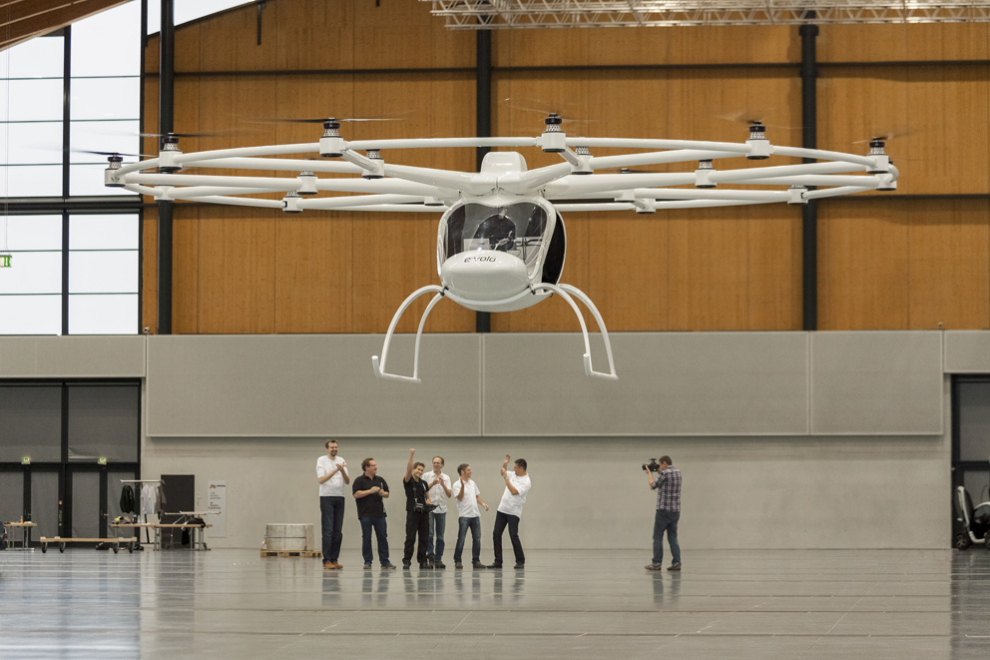
AscTec and E-volo VC 200 takes flight.

vc200_first-flight_01.jpg?width=550

E-volo’s Volocopter is a revolution in aviation Made in Germany. Safer, simpler, and cleaner than normal helicopters, it has a unique way of moving – a groundbreaking innovation. The Volocopter is an environmentally friendly and emission-free private helicopter. Instead of one combustion engine, eighteen electrically driven rotors propel it

http://www.suasnews.com/2013/11/26112/successful-maiden-flight-of-the-worlds-first-green-helicopter/

Read more…
Distributor

Iris with FY-G3 brushless gimbal

Just wanted to share a quick video I took testing out the Iris quadcopter and the FY-G3 gimbal.  If anyone is interested they can find out more details of how I went about attaching it here, otherwise a short summary below :-)

I just made a quick mount for the longer arducopter legs, and a mount for the FY-G3 gimbal that uses the existing gopro 3 mount that comes with the Iris, so that it can be attached/removed without needed to do any modifications.

Read more…

Give The FAA Preemptive NPRM Feedback

3689512329?profile=original


Be sure to tell them you are ready to get to work legally and share your ideas for progress etc. Tell them that regular access to the NAS in 2020 is unacceptable. SHare your thoughts on pilot and observer certification, aircraft certification and limitations on autonomous aids.


https://www.faa.gov/about/office_org/headquarters_offices/avs/stakeholder_feedback/arm/

Read more…

3689559700?profile=original

Hello All,

It is time for yet another diydrones vodcast on google hangouts (diydronestv@gmail.com) and in this episode I am glad to have the leadership team of the UAV challenge that took the world by storm on my next vodcast episode today.

Over 50 teams (http://www.wcuavc.com/teams.html ) has already signed up for this challenge and I believe it is going to be a stiff one.

The hangout will open 15:00 pm UTC Time (11:00 pm New York, 16:00 pm UK time, 17:00 pm Swiss/S. Africa time) where I will start sending out all of the invites and will start at 16:00 pm UTC Time.

The interview will be on our YouTube channel for you to watch over and over.

Hope to see all there.

3689559724?profile=original

LEADERSHIP TEAM

3689559733?profile=original

3689559813?profile=original

Read more…

Introducing the Albatross UAV project

3689559673?profile=original

3689559704?profile=original

3689559688?profile=original

3689559601?profile=original

Hello all,

Where to start... Well, My name is Justin, and aviation is my life. I grew up in a family with aviation in our heart and blood. Everyone in my family has been in some sort of aviation, whether it is Full scale helis, prop jobs, jets/airliners, hang gliders, or even home built aircraft. I solo'd at 18 yrs old with only 9 instructor hours, and continue to enjoy every aspect of aviation. I am currently serving in the USAF as an aircraft electrician, in order to finish my Aerospace engineering degree. (Which is not far from being complete!)

Onto the project! 

The albatross UAV project came to me one night while laying in bed (so original isn't it?!). My goal was to provide a high grade, inexpensive UAV platform with unrivaled performance.

My goals?

A standard 4-6kg+ MTOW

Plenty of room for sensors, batteries, and equipment

Easy 1 hour flight times, and up to 4 hours (which is the goal... of course we can't be sure to initial flight tests)

Breakdown, and transportation ease!

Wide flight envelope

Sexy and appealing looks

Last but certainly not least, EFFICIENCY!

Airframe introduction.

The wing: The wing will have a wingspan of 3000mm, and wing area of 68.38dm^2 (in other words, 118" span, and 1060in^2). It consist of an optimized foil, and a forward swept planform. The foil is designed to ensure low stall speed, while maintaining a high max efficiency, and large cruise window. The wing planform Utilizes this foil nicely. It is a relatively high aspect wing with a ratio of 13.2. I have found that this moderate aspect ratio is preferred at RC Reynolds numbers for numerous reasons. an Aspect ratio of 12-15 allows for easier, and stronger wing structure, it allows for slightly higher Reynolds numbers, allowing airfoil's to work properly, over a wider speed range, and allows for easier built in retract, and or component bays. Obviously, we want to achieve all of the above, with minimal impact on performance. Of course a Higher AR wing would be more efficient, but at a significant cost (both in actual price, and giving up benefits.) The wing will be built with built in component bays, allowing for RC rx install in one wing, and Vtx install in the other. Not only does this allow for more room in the aircraft, but it allows for proper separation between Vtx and RC rx. The wing is forward swept, which helps minimize the chance of tip stalling while on approach with your UAV, which may as we all know, be overloaded. (there is nothing as horrible as losing your beloved UAV platform and equipment!). The downturned style tips aren't just for sex appeal, they actually reduce drag and tip vorticites, as well as decrease stall, while improving stability!

The Fuselage: The fuselage is designed around the user. It is designed to have plenty of usable storage space. Whats this mean? Well why would you have a tall narrow fuse? This not only makes is a huge PITA to work in, yet it limits how YOU want to lay out your components! The fuselage is approximately 740mm long, 150mm deep and 200mm wide. To avoid excessive fuselage/wing intersection drag and interference the fuselage is built in a slight trapezoidal shape, only to an extent that wouldn't hinder storage capacity to much. This translates into a fuselage with more usable space than the popular SkyHunter. I haven't mentioned efficiency yet. Lets not forget about that! The fuselage is actually a very efficient shape, minimizing the drag left behind. (even though it will only get chewed up by a prop...). It is also efficient in cooling. It will be designed with a NACA duct in the nose, which is a high pressure region. It will consist of an exhaust right above the motor, which is the lowest pressure region. think suck and blow. While creating a pressure differential it actually pulls air through the airframe keeping necessary components nice and cool.

Tail/s: The tail is an Inverted V design. Why? Simple really, an Inverted V improves efficiency while decreasing drag. It is also naturally more stable in a banked, and coordinated turn. The Inverted V allows for twin tail boom design, allowing for a large diameter prop. It also raises the ground clearance of the tail on landing and takeoff.

Breakdown and transportation: The number 1 reason for keeping airframes small is due to transportation and storage. The Albatross is designed to fit into a box no larger than .35m X .5m X 1m. In reality the case could be much smaller. How does it do this? The fuselage is 740mm X 200mm X 150mm, needless to say, it was designed within the required specifications. The wing is 3m long! However, it simply breaks into 3 1m long sections. The twin carbon-fiber tailbooms are 700mm each. The tail will be hinged at the center, and consist of two 440mm halves, allowing it to fold into one 440mm piece. Not only does this make it easy for the end user, but it reduce's shipping costs to your door. No more paying as much as 50% of your aircraft on shipping alone!

Goals:

My Short Term goal is to finish analysis and development. I am planning on starting a kickstarter to fund the initial molds and production costs. The current Design consists of a fiberglass fuselage, twin carbon fiber booms, and either a foam core/obeche covered wing, or an all built up wood wing. It will come with optional fuselage formers/inserts. These will be laser cut, allowing the builder the option of using them or not. These peices will consist of a retract mount (offset similar to an A-10c aircraft nose wheel, to allow for minimal effect on usable space) as well as numerous mounts and shalves for components and or batteries. Of course, as mentioned this will be up to the customer whether or not he/she will choose to install them. It also allows for some open source design in case anyone wants to improved upon, or create their own after market laser cut parts. This airframe would be available at a goal price of around $500 usd. This may or may not be achieved, but it is my GOAL. I consider this a reasonable goal considering similar aircraft such as Hobbykings UAV-3000 are capable of being produced around $300. I hope that my few added features are not enough to out-reach my goal.

Specs:

Albatross:
Wingspan; 3000mm
Wing Area; 68.38 dm^2
Root Chord; 300mm
Tip Chord; 160mm
Fuse Length; 740mm
Fuse (max) Width; 190mm

My Long Term Goal is a Albatross Pro version. The Albatross Pro will have a slightly enlarged fuselage,  more wing area, higher MTOW, change in airfoil, fully molded wings and tail, and more precise construction. These changes would increase MTOW, and cruise speed/efficiency to a more specified range. It would also consist of a few ease of operation features such as built in Cannon-plug style connections for easy quick-disconnect assembly. This means that when you take off the wing, there is no servo connection to fumble with. It would also consist of some ease of assembly mods such as quick disconnect wings, booms, and tail, requiring no tools to use. (Think, Crutch/cane style push button. This would be located under the flaps.)

Specs:

Albatross Pro:
Wingspan; 3000mm
Wing Area; 75.216 dm^2
Root Chord; 330mm
Tip Chord; 185mm
Fuse Length; 890mm
Fuse (max) Width; 230mm

Here is a more in-depth design log on my RCG account. The wing planform, and laminar foil research was originally from a previous project, before I realized its potential in FPV/UAV. Although the introduction of my UAV/FPV platform is fairly new, a lot (many years worth) of prior personally research has been incorporated.

I am currently in communication with a few different OEM manufacturers for an initial Hobby version, and a long term Pro Version. If you know of, or you are another OEM manufacturer feel free to contact me! It would be much appreciated!

Please, feel free to comment, discuss, and provide constructive criticism! After all, this is my first post on DIY Drones, so please be nice!

Read more…