All Posts (11086)

Sort by

Camera triggering using transistors (APM 2.5)

3689517713?profile=originalI Just found a quick way to hook up APM2.5 to take photos using transistors .

What we need

2 x npn transistors 

2 x 10K resistors (Rc)

2 x 6.8K resistors (Rb) ( this was sufficient for me to saturate the transistor )
And a small pcb and some wires .

I had a nikon coolpix lying around so I opened it up to access the switches.Carefully remove the
upper cover which covers the switches within .You can just google how you can open it (Be carefull about
the Capacitor which is used by flash , you may get a sting if u touch its leads ).

Find the switch which is just below the trigger of your camera . Check its leads (normally its a
small push switch ) . Check which of its terminals are connected to the ground using a multimeter .
And do check the voltages on the other leads when powered on ( They are normally pulled up and may show you
voltage little less than battery ) .Normally there will be 2 such leads which are not grounded and other two grounded.Connect wires ( blue and purple ) to the 2 leads which are not grounded.One will be for focusing and the other one for clicking . Connect 2 wires to battery +ve and -ve terminal (Red and Brown ) .

So just to check whether all is going well and connections are made proper . You can try connecting one
of these wire to battery ground . If nothing happens try grounding other wire . One of them will
let you focus the camera ( you can see it on lcd ). Just when u get the green square on lcd connect the
other wire to ground while still holding the previous wire grounded . If all connections are proper
,the camera should take a picture.

Now we will have to achieve this with a digital signal from APM .For which we are using transistors as switches to
connect those wires to ground .
Just check the circuit diagram( very simple ).3689517549?profile=original

3689517775?profile=originalIn the above image the wires i hold go to APM ( brown - gnd ; red (AN2) and yellow(AN3) focus and trigger pins ) .

While soldering make sure you connect both the grounds together the APMs and camera battery's .


Now for the code ( I have attached it with this post ). I took a simple bypass . I used ch6 input to trigger camera overriding the normal ch6 function .So if you plan to use my code you better be sure you are not using ch6 input .You 
can see it in mission planner config screen . Just make sure ch6 function is set to none .
The code that i have added is in the CONTROL MODES tab in function read_trim_switch ( 10 Hz)

/* This part is to trigger camera transistor pins */
static bool trigger_flag_my = false; //flag to keep track once the ch6 switch is pressed
static char trigger_count_my = 0; // to count the number of times it comes to the function to keep track of time . each count represents 0.1 sec .

if( trigger_flag_my ) // if triggered
{

digitalWrite(AN2, HIGH); // focus pin
trigger_count_my++;
if( trigger_count_my > 10 ) // wait till its 1sec
{
digitalWrite(AN3, HIGH); // capture pin
}
if( trigger_count_my > 12 ) // wait till capture input taken
{
trigger_count_my= 0 ; //Reset all variables
trigger_flag_my = false ;
digitalWrite(AN2, LOW);
digitalWrite(AN3, LOW);
}

}
else
{
digitalWrite(AN2, LOW);
digitalWrite(AN3, LOW);

if( g.rc_6.radio_in > 1500 )
{
trigger_flag_my = true ;
trigger_count_my = 0 ;
}
else
trigger_flag_my = false;
}

/// END OF CAMERA TRIGGER

Add this at the start of the function .

And add this to initialise the pins in SYSTEM tab in the function init_ardupilot just below led pin definitions ( just to make it easy to locate in case u want to remove it later )

// setup IO pins
pinMode(A_LED_PIN, OUTPUT); // GPS status LED
digitalWrite(A_LED_PIN, LED_OFF);

pinMode(B_LED_PIN, OUTPUT); // GPS status LED
digitalWrite(B_LED_PIN, LED_OFF);

pinMode(C_LED_PIN, OUTPUT); // GPS status LED
digitalWrite(C_LED_PIN, LED_OFF);


//---------------------------------
pinMode(AN2, OUTPUT); // Cam focus
digitalWrite(AN2, LOW);

pinMode(AN3, OUTPUT); // Cam trig
digitalWrite(AN3, LOW);
//--------------------------------


Once done with the code the last thing to do is hook the ch6 of your Tx to APM
and go to radio calibration tab and check the ch6 value . Make sure you set it up such that when u
switch the value goes above 1500 and when normal its value is less than 1500 .If not you can change
it in Transmitter setup .

Hope it works for you ! Thank you !

3689517740?profile=original

Read more…
100KM

Techpod review

 T5PDC7L39wrLBQ4UStVFZMkFpcUYD62eYC73YplnXTtRkJfy1PhryxrZAySTNobVvtRpTvOG7ixdSgRfuJrrYmxOP8iQizebAMR6AOMvkuwdTKjCERE9ii-uTS-AqK3WCVCxHR8olvpGYlMdHIWTyWfOnelE5bXiFCzaOTDX6bi09yxJqWmtxH9DPeRU3N27O8KyUMcfYMFALVSPyxjLkCQu_2jxYYLE3EMUgyeR7yx2Ir6X0c-G2Qtks2V245Ha8oUV2Ch6yOpKE1JaXpjFGKWabitT765IEwgNclRNGZyVw1yj-FSsAM3KS6xgAFMbrfBtTVGyz9avyAeALSwFLzryyYK7MLHT1x2fWTtsE1PnXjIeZ4EAAqginoJTq4TI-OCBPMw59sa9nI0JG-sMI48THJKEhUcyQlV0A7JGkWQkZt-M9nfQB46hTTsFsfWOGqRKuhLZTnvsTs7oKh5nzWeAng8Vbt8L


Techpod is a special design FPV with hundred of hours of computer calculation and simulation went through during the design stage. With a high aspect ratio glider like wings, it is capable of long flying time. The designer claim for more than 4 hours of flight time with 2 pieces 6S 5000 mah battery in parallel.

I build this plane for aerial photo purpose. I’m looking for a flight time of about 90 minutes. Longer flight time means more battery, thus weight to carry which may affect the quality of flight control.  My current camera ( Canon S100GPS ) battery life may not last more than 70 minutes of continuous shooting at 3 seconds interval.

The build

Kit arrived in double box protection, upon unboxing, I found all the components are neatly pack with plastic bag and no damage. The furnishing of the EPO parts is above average with smooth wings top surface. The fuselage side surface also smooth make this kit looks good.

HobbyUAV web site provide a very detail building video tutorial so I’m not going to repeat here. This is certainly not a beginner kit. Your may face some difficulty if this is your first time building a radio control airplane. If you have some experience under your belt, you’ll good to go.

I highly recommend you watch a few time of the video, lay out all the components and dry fit it to see if you need to sand some parts to get a proper fit. This will also prevent you from fitting the wrong parts at wrong place which is difficult to reverse.

My kit go together well with some sanding here and there. Pay special attention to the T tail structure and make sure the stabilizer is perpendicular to the tail fin.

I don’t like the motor to be permanently mounted to the firewall. I use a motor extension so I can remove the motor easily if needed.

Radio and power set up

Because most of the servo need long extension, It will be a good idea to use heavy gauge (26#) twisted servo wire as your extension wire. If you can do some soldering job, it is good that you make your custom extension wire for neat installation.

You’ll need 6 pieces, preferably digital 9 gram micro servo for all the control surface. You can use a 15 gram mini servo for elevator control if you like it or feel not so comfortable with a micro servo controlling the elevator. I’m using Savox SH 0257 MG with good result.

The recommended motor is Turnigy G10 Brushless Outrunner 810kv but since I have a Turnigy C 4250 700KV motor on hand, may be a little overkill for this plane. I just used it for the initial test flight. I’ll change to some dish type motor like T Motor 4008 340KV in the future. Speed control is 50 A Turnigy ESC. I’m using a external BEC ( CC 10 A BEC ) to supply current for the electronic. The build in BEC from the ESC may not able to handle those long servo wire. An APC 12x6 propeller and 4S 5000mah battery finish the power package.

Wings hold down modification

The default wings hold down method is by clamping the center section with two pieces thick plywood and a long screw. I don’t have much confident with it so I do a simple modification as shown in the picture. Now I’m sure the wings will not give way in any flying condition. The modification is quite simple. I cut two lengths of plastic tube, cut off some foam and glue them into the wings as shown in the picture. Next I insert a 3 mm music wire into one end of the tube, tap and use a 3 mm screw to secure it permanently. The opposite site also use a 3 mm screw but it will be removable  After I plug in the wings, I can secure the wings with the screw from outside.  I have to stretch that the default method should work well as per design, this is just my personal opinion to make it feel more secure.

Test flight

After about two week on and off building, now the moment has come to test flight the plane. As a radio control airplane hobbyist, we always get excited whenever we fly a new plane for the first time.

Double check all the control surface, CG and all wiring connection, a fellow RC buddy lightly toss it into the winds while I have about 70 % throttle and a little up elevator. The plane climb up with authority at this throttle setting. Once reach about 100 meter altitude, I bring it to the end of the runway, make a procedure turn and do a straight and level flight to trim the aileron and elevator.  I just need “some” trim and I am able to let it flying straight and level hands off. The elevator control feel solid and very responsive but the aileron control  feel a little sluggish. I think this is due to the fact that it had a long wingspan. The response of the aileron input is a little slow especially when I want to level out the wing from turning. At time I had to apply full counter input to bring the wing back to level. On subsequent flight I increase the ATV of the aileron and it responds better.

Landing the Techpod is very easy, it has a very good glide ratio and also very graceful low speed handling. Just set up the final approach about 150 meter away and into some head wind with altitude about 50 meter, the plane will glide down gracefully , you may control the descent rate with small throttle input.

For those of you who never fly a sail plane, you may not comfortable to see the wings “ flap “ during flight. The designer had assured us that the wings is plenty strong and the flapping action of the wings is by design. He had a video to show just how strong and flexible the carbon wings tube is.  

One must remember that this is a FPV plane, not a pylon racer. It will NOT handle high speed, high G maneuver well and may cause flutter. Don’t ask me how I discover this.... : ) but I can tell you my plane is still flying.

Overall, I am very satisfy with the performance of the plane in full manual mode. No significant bad habit show up in the test flight. I am also confident that with a proper size motor, the plane will fly equally well in auto mode.

Read more…

3689517613?profile=original

Most of photo mapping online services and several softwares as Photoscan use Self-Calibration method for modelling internal geometry of cameras. While this approach is simple and practical, don´t provides the best results because the low convergence and redundancy of a tipical aerial survey.

Atachhed to this blog there is an example of a full field calibration of a Sony Nex 7 with a Sigma 30mm F2.8 (tipical setup in Bramor UAV). Thanks to the large calibration field, sharp pictures were taken with the same focus setup that used when flying (The focussing ring is blocked in Bramor).  If you are lucky enough of own this camera/lens maybe you can try this calibration certificate. All right, for sure, your camera will be slightly different to this, but I dare say that this modelling will be more accurate than that obtained by self-calibration.

Sony%20Nex7%20Calibration.pdf

Read more…

X5 wing equipped with APM 2.5

Hi all, following the project of making specific instructions for each type of aircraft equipped with APM 2.5. Today I present the tests in auto mode executing a mission, this wing x5 has much potential as drones, for video and photogrammetry. the development of these applications www.makedrones.com blog we will develop in the next 30 days

Read more…

I have been working on improving the TradHeli slowly but surely over the past few months.  One major aspect I've been working on is the ability to use full Pitch and Roll I-term.  Currently in 2.9.1 these are "Leaky" which limits their build-up to avoid tip-overs on the ground.  I have created a robust Take-off detection scheme that allows us to switch over to full I-term (as the multirotors use) for much better dynamic flight.  However, the system must switch back over to "Leaky" I-term once it touches the ground again to avoid tipping over.

I have managed to accomplish this, based largely on the work of Leonard and Randy who provided such a great Alt_Hold controller that if can also quite accurately detect a touch-down.

Another minor part of this is that while the heli is on the ground, I limit the negative collective pitch to less than full negative, so that we do not push the heli hard into the ground.

Here is the video from today using my 450 testbed.  I'm not working on this with my large 600.  Back to the field!

This code exists only in my branch which is based on 2.9.1.  I have not pushed these latest changes yet but will later tonight.

Read more…
MR60

3689517552?profile=original

Hello,

In a search to film with a HD camera I made different tentatives with all kinds of materials and devices to avoid the famous "Jello" effect. I tried moongel, I tried elastics with foam, I tried rubber grommets...everything lead to Jello!

I though I would be unable to get rid of it until I got the following idea, inspired from military strategy: not to try to block an ennemy wave at first defence. Rather, build successive defences in cascade : a bit of the attacking wave goes through the first line of defence to the second line; a bit of the bit of the wave goes through the third line, a bit of the bit of the bit of the wave dies on the third line, etc. These cascding lines of defence will utimately get rid of most of the vibrations to the camera. That was the idea, so how to apply this on a quadcopter ?

First decision was to attach the camera gimbal on the bottom plate because I think intuitively that is the best place to start with less vibrations (alternative was to use the sonar mount between two arms, but then I am way to close to the vibrations sources).


First line of defence, the bottom plate


Thus the bottom plate had to be the first anti-vibe line of defence. As shown in the picture below I decoupled this bottom plate from the rest of the frame with 8 M3x20 rubber dampeners (instead of screws):

3689517438?profile=original


Second line of defence, transversal booms to hold the camera gimbal:

I purchased a one meter U shape aluminium boom (10mm x 10mm) that I cut in two pieces of the length of the bottom plate plus a few extra inches to hold a camera plate (will be shown in next picture). These two booms are attached in parallel to each other and screwed on the bottom plate with two M3x10 rubber dampeners.

3689517505?profile=original


Third line of defence, the camera plate:


The camera gimbal is suspended on a aluminium plate using the two parallel booms. This aluminium plate is attached to the booms with four M3x15 rubber dampeners as shown below,

3689517566?profile=original

The extra trick is to keep an extra rigid link between the camera gimbal and the frame. For that I reused an idea that was posted previously on this forum and bought at servocity the famous servo blocks. This is not ideal to avoid jitter of servos in mouvement but this is the best I found until now. Because now the best would be brushless gimbal and that shall be my next project (waiting to do the investment, it is not cheap).

So with all that I did a quick test flight that you can see in this youtube video. This video was not corrected nor transformed. You will see that except mouvements of the gimbal (i flew in stabilize with lots of pitch/roll corrections), the video is absolutely without any Jello.

Mission accomplished.

By the way, the music of the video is a credit for Jake Wells who inspired me.


CU,

Hugues


Read more…

Cheap flippin' quad (and...go big, or go home)

Part one of the title..at under $70 my V959 is cheap, and in this video, it flips. Anyway, I just thought I would share a new adventure!

Alright, part two of the title...I am wanting to make the move up to a bigger quad, and want some advice on what route to take...? There are so many options it seems, and I don't want to make a decision I regret. I have been reading, and pondering, and reading some more, but want to hear some opinions. I am not above building my own, but, I have never built a quad before. Also, I have considered something like the DJI Phantom, but wonder if they are the best bang for the buck. Thanks in advance for any help you may have to offer.

Read more…
Moderator

3689517455?profile=original


After an hard work  VR Lab team finish the porting of AP_HAL library to VRBRAIN.

Now we start doing first test on Arducopter rev 3.0 and Arduplane 2.71 . 

Emile yet start to do first test on Arducopter rev 3.0 the great news is  that in the next week we start to doing the first test of Arduplane on VRBrain . Our beta tester is Daniele Avagadri . He is member of Virtual Robotix Italia team and have a 12 years of experience on RC airplane.


here info about VR Brain the price start from 150 euro.

http://www.virtualrobotix.com/page/vr-brain-v4-0


3689517390?profile=original 


3689517417?profile=original


Last video doing by Marco Robustini


Here you can find the firmware repository :

http://code.google.com/p/vrbrain

ap_hal project is available in ap_hal_newdir branch.

This is mini site for ready to fly firmware :

http://vrbrain.wordpress.com/


for more info send a mail to : info@virtualrobotix.com


original blog post : http://www.virtualrobotix.com/profiles/blogs/arducopter-arduplane-and-ardurover-firmware-based-on-ap-hal-libra


Thanks to Emile , Andrew , Pat and the other member of the team for the support to our work and for the ap_hal multi platform code revision.

Best

Roberto Navoni


Read more…
Moderator

T3 Qube results

3689515735?profile=original

This T3 round was really quite the thing. As such everybody gets a prize! Chris assures me that the 3DR T shirts are very cool. So far he has failed to produce an image of a bumpy jumper person wearing one to prove that is so.

As ever the trying was not without drama and has moved the code and thinking forward a little for all. That's what makes competitions so good for this community. Its why a hat needs to be tipped to all those brave enough to try.

The winning flight really was stunning from many angles. A great looking cube, very long flight time and all hands off to boot.

Top three prizes goto:-

1   Steve Westerfield,  AutoQuad,   longest loiter in each corner  42 minutes between 3 and 5 minutes at the corners
2   Aerhead,                AutoQuad,   a really great looking cube
3   Richard Boyhan     APM, for trying so hard.

For his efforts Steve receives an APM 2.5, Aerhead and Richard uBlox GPS modules. Many thanks to 3DR for supplying these prizes.

Also entering and receiving a T Shirt for their flights

Rob Lefebvre
Randy
Ted Van Slyck
Bruno Guerreiro
Scott Berfield

The community should raise a glass to these multirotor adventurers!

3DR will reach out to everyone with coupon codes to arrange delivery of their prizes.

From me, thank you all for entering it has restored my faith in the T3 again!

Bruno you legend, three months of RC experience and you submitted this flight.

3689517366?profile=original

Scott, sorry we made you crash.

We will announce the next one shortly.

Read all the stories about this round here http://diydrones.com/profiles/blogs/t3-season-two-the-multirotor-one?id=705844%3ABlogPost%3A1136977&page=1#comments

Read more…
Moderator

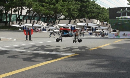
Hyundai Flying Car

hexadecagoninflight.jpg

Not sure I have picked the right named  rotor number for this one. I called it a hexadecagon. 

A chap said of an ultralight pilot that I knew after flying over a large body of water (Irish Sea) in a very very dodgy aircraft. "Balls the size of melons and a brain the size of a pea" 

I don't think I would have sat in this, especially as the chap in the cape in the video is driving it!

http://www.suasnews.com/2013/04/22397/hyundais-flying-car-manned-hexadecagon/

Read more…


Hello everyone,

Today I want to share a new initiative that I have, is the creation of a blog where I colacare the instructions step by step how to build drones. instructions will be specific for each type of aircraft, that have ensured that many frustrations with generic information that sometimes requires previous conocimeinto to build a drone. My goal is that if I place specific instructions for each type of drone (eg x5, raptor, skywalker, etc..) this ensures that the learner's curve is reduced, and errors are reduced.

This initiative came about many questions I get from the post that I publish diydrones forum.

Blogs will be in English and Spanish, I apologize if there are mistakes in English, I am using a translator. Will do my best efforts to create this is my blog

http://www.makedrones.com

Any suggestion is welcome.


Read more…

Flip and spiral death from 100m, solved

3689517144?profile=original

I recently had my 4th in-flight motor shutdown on my old 3DR Quad - I think I've finally figured it out so I thought I'd share the story so others can check for the same problem as well as show some logfile diagnosis.


My earlier flip deaths were from quite low so I didn't have a chance to see what was going on, and I didn't have the motor logging on to see which one shut down. I also suspected I could have been having brownouts in the past as I was powering my gimbal servos from the signal pins for a while until I discovered that was *BAD*.


This one was from high enough that I could observe and try a couple of things on the way down. It definitely still had power to the APM and some of the motors as you could hear it trying to correct itself, I switched out of auto mode into stabilize, pulled the throttle back to idle then up again in the hope it would restart the 4th motor, but it didn't. I heard the other three spin up again and whine dramatically but it never corrected. It thumped into the ground, broke all the props, bent the arms, but all the electronics survived (even the S100 camera). Reinforcing the message: NEVER FLY OVER PEOPLE! For sure that would have caused more than a bruise if someone was below it.

From the logs it looks like it was the #4 engine that quit (rear-right on a quad), as you can see it suddenly pitches up and rolls right, commanding more power for the #4 and less power to the opposing #3 engine (to no avail, as there's no RPM feedback in our current hardware so it doesn't know the motor is out).

3689517252?profile=original

3689517154?profile=original

The frustrating thing was that after this crash when I tested the motors they all ran fine, just like the previous flip crashes, so I was at a bit of a loss to diagnose the problem. I thought it could be low power and bad ESC programming that would cause the #4 ESC to cut out early, so I ran an old pack right down and all 4 motors slowed down in sync together as the voltage dropped off.


So I knew it was something with the #4 motor and it was unlikely to be the ESC as I'd replaced that before after one of the crashes. I removed the props, ran the motors and pulled and jiggled all the wires around to check the connections and...

BINGO!

The motor glitched then restarted. I pulled the cable some more and it stopped altogether. Here's a vid showing the problem:

https://www.youtube.com/watch?v=_iB5r6-AE-o

Turns out a bad wire connection to this motor had caused me 4 crashes and lots of headscratching. One more for the 3DR Quality Assurance department I think (well, 4 more...)

3689517215?profile=original

So a lesson for all: when you're finished a new build and periodically thereafter, remove your props, run your motors and jiggle all the wires around to check you have solid connections!


AC.

Read more…
T3

FPV Camera Mount

3689516892?profile=originalI can't be the only one who has had some trouble coming up with a good way to mount an FPV camera on their quad. So I designed a simple snap together mount that I would like to share! This thing presses together and glues to your frame with some hot glue. It weighs 5 grams. I designed it with universal (should be anyways) slots for mounting screws. Just lift the camera off the board a bit with spacers and screw it on with servo mount screws. Below is the CAD file. I am glad to share with anyone who has the ability to make this themselves. If you don't, but want one: go to my site openrcdesign.com (still a work in progress), click on FPV CAM Mount and buy one for $15.  Ill have a post about the frame its mounted on in a few days. The APM mount is of particular interest. 

3689516973?profile=original

3689517005?profile=original3689516987?profile=originalLink to CAD file

Read more…

The New 3DR Store Has Landed!

3689516797?profile=original

You've likely already received a message in your inbox to set up your new store account at http://store.3drobotics.com

We're moving to a new, open source, more flexible platform called Spree.

All of the old DIY Drones store customer data has been migrated to the new site.  For security, we just need you to set a new password using the link in the e-mail sent to you.

Both old and new stores will be open and accepting orders for the next 2 weeks.  We'll then shut down the old DIY Drones store to new orders, and leave it open for reference only for another 2-4 weeks.  We'll then turn the old store off, and have the data backed up for historical purposes.

We've spent a lot of time reviewing and testing the new store, but there will inevitably be issues.  We'll do our best to monitor this thread, but feedback is best received at feedback@3drobotics.com.  Additional enhancements to the ordering experience will be rolling out as well in the next few weeks.

We appreciate your business here at 3D Robotics, and look forward to providing you with the most innovative and affordable open source UAV products for a long time to come.

Keep on flying!

John C.

Read more…

3689516743?profile=original

Published April 18, 2013 - Associated Press

The Florida Legislature has passed a bill limiting law enforcement agencies' use of the remotely controlled aircraft known as drones.

The House unanimously approved the Senate's bill (SB 92) 117-0 on Wednesday with no debate.

It now goes to Gov. Rick Scott. The governor has previously said he would sign it into law.

The measure restricts the use of drones to the prevention of imminent danger to life -- a kidnapping or a missing child -- or serious damage to property.

It also makes police get search warrants before using drones to collect evidence. An exception would be a credible threat of a terrorist attack.

Only three law enforcement agencies in Florida are currently licensed by the federal government to fly drones. None are yet using them.


Read more: http://www.foxnews.com/politics/2013/04/18/florida-lawmakers-pass-drone-control-bill/#ixzz2QqwS5Maf

Read more…

Going up?

Going up? This is about as daring as I would get with my little v959, especially considering there were pretty significant wind gusts. This video does demonstrate a couple things. First, I can get a fairly good birds eye view of a neighborhood with a camera equipped quad. A better quad than my glorified toy could be a useful tool in post-disaster scene surveillance. Second, it is slightly difficult to see, but there is actually a visible squall line in the background at one point. Again, a higher quality quad could possibly be used to research weather. Things I think about while playing with my toy, and imagining my first "big boy" quad.

Read more…
Moderator

drone_4-1024x577.jpg?width=350

Patrick spoke with with Bryan Galusha at the recent Robotics block party and he had something to share with sUAS News.

We are excited to announce the Fighting Walrus fully-integrated RTF airframe!  This ready-to-fly airframe incorporates the features what our customers wanted most:

1.  Streaming 1080p video

2.Manual control with the iOS device

3.  Low cost Ready-To-Fly kits

The RTF Airframe will integrate with the Fighting Walrus Radio to enable an unparalleled ground station experience.  Video streams from the drone are geo-encoded and embedded into the iOS application, allowing users to monitor drone orientation and position while watching the video stream.

Full story http://www.suasnews.com/2013/04/22339/fighting-walrus-fully-integrated-rtf-airframe

Read more…

3689516544?profile=original

I have been working on a fork of the Arduino IDE for use with the Pinocc.io project. With all the improvements I have made, it became my default go to for any Arduino code uploading, so it was inevitable that I would bake in ArduPilot HAL as well!

My current focus is on the OSX build, but I am fairly sure it will build alright on windows, probably wont look too great until I focus on that.  I wanted to remove the ugliness from the IDE and improve the UX.

The main big thing that I added was the concept of "Workspaces", this allows you to maintain completely separate sketchbooks for each of the platforms. Right now I have them hardcoded, but I intend to make it configurable via a new preferences window I am about to start on.  The workspaces currently are Arduino, Ardupilot and Pinoccio.  These default to ~/Documents/{workspace name} such as ~/Document/Ardupilot.  

I integrated the HAL classes that Pat Hickey worked on with the community fork of Arduino, and adapted them to work within the new 1.5.x setup. 1.5.x introduced platforms.txt, which makes the whole thing a lot simpler.  The ArduPilot HAL menu is enabled if you select an ardupilot board from the boards menu. This allows you to build standard, or coreless for the HAL codebase. (just like the community fork does).

This is very much alpha quality code, I am no java developer, but apparently I am more of one than the original authors of the Arduino IDE ;)

The project source is located here: https://github.com/dchote/pinoccio-ide

Latest binary for OSX is located here: http://cloud.chote.me/2I3z2g2S0u3i

I would love feedback on this, also if there are any feature requests, please let me know (preferably via ticket on github!)

Read more…

3689516628?profile=original


Researchers at the University of Illinois at Urbana-Champaign developed new microbatteries out-powering even the best supercapacitors. These could drive new applications in radio communications and compact electronics, such as drones - the batteries are rechargeable and can charge 1,000 times faster than competing technologies!


"Any kind of electronic device is limited by the size of the battery – until now. We can reduce by a factor of 30 today's required size. Now we can think outside of the box. It's a new enabling technology. It's not a progressive improvement over previous technologies; it breaks the normal paradigms of energy sources. It's allowing us to do different, new things."

Read more here .

Exciting for us: in a near future, we could have 30 times the range for our drones in the same package, with ultra fast recharging times.

The National Science Foundation and the Air Force Office of Scientific Research supported this work.

Read more…