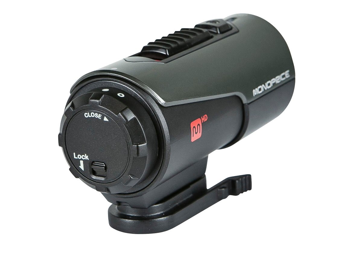
Capture all the action with the new MHD Action Camera from Monoprice!
The MHD boasts a full, high-definition 1920x1080p display with 24-bit color depth at 30 frames per second. It can also be set to capture at the lower 1280x720p, 24-bit resolution with 30 fps. It features an ultra-wide 120° field of view, so you can really get up close and personal with your shots.
The camera is waterproof to depths up to 10 meters without a separate outer enclosure. It is also shock, dust, and freeze proof, all features that are necessary in an extreme sports action camera. A waterproof microphone allows you to capture the entire audio/video experience. A two-axis gyroscopic sensor ensures that the video maintains the proper orientation.
The MHD weighs only 3.9 ounces and measures 3 3/4" long, 1 7/8" high, and 1 1/2" wide. It comes with a mounting bracket and can also be mounted onto a standard 1/4"x20 threaded mount, giving you maximum flexibility in how you use it.
A one-touch slide switch is used to start and stop recordings. The switch is about 1" long by 3/8" wide, so you can easily start and stop a recording without having to remove your gloves.
A locking and removable cap on the rear of the unit gives access to the resolution selection switch (FHD or HD), the hardware reset button, the micro-SD card slot, which can accomodate a card up to 32GB size, the mini-B USB port for charging and data sync, and a Micro HDMI port for direct video output to an HDTV. The internal battery has sufficient charge to allow up to 3 hours of continuous recording and up to 6 hours of standby mode.
In addition to being used as a video camera, the MHD Action Camera is also a 5 megapixel still camera. A large button on the top of the unit is used to snap pictures in Single Photo, Burst, and Time Lapse modes with 24-bit color depth.
The camera has plug and play operation and is automatically recognized as a storage device by Windows and Mac computers. Integrated software can be installed to a Mac or Windows PC to allow access to the internal settings. The software is compatible with Windows XP SP3 or later or Mac OS X 10.5 or later.
Additional Mounting Accessories: Helmet Mount, Board Mount, Suction Cup Mount
I'm back from a 3 week holiday in Namibia, I took my small Swift II FPV ship with!
What fun, I flew over Walvis Bay's lagoon, game farms, dunes, beaches, chasing quad bikes, kite surfers, fantastic landscapes and mountains.
I decided to compile the best few seconds of all videos into one and posted it. It's long (15 minutes) but there are some great moments. Youtube does not agree with my music selection, so please let me know if you're unable to view it.
Please excuse the video quality, I successfully destroyed my Horyzon HD just before the trip and was left with an iffy HK Wing Cam.
I'm now building the ultimate Swift II complete with expanded mid section (blunt nose), APM 2.5+ and MinimOSD.
I'm loving this setup, it's really a grab-and-go FPV dream.
There is open-source library implementing the CANaerospace protocol, targeted for microcontrollers and Linux. It is compact and easy to use in embedded systems with few amount of memory and limited processing power (such as most drone autopilots).
It is released under MIT license, so there is no problem if you want to link and distribute it along with your closed-source project.
The time of randomly mixed I2C, PPM and UARTs should be over.
1. Reliability
The first reason is reliability.
CANaerospace allows the use of redundant CAN buses as well as redundant units. I.e. you can connect each device to the two CAN buses simultaneously, and if one bus fails other will keep going (so there is no single point of failure). In case of unit redundancy you can use two identical mission-critical devices, and if one device fails you'll simply switch to another and save the world.
Note that this library supports CAN bus redundancy in fully transparent way, i.e. your application simply will not care about how many buses are currently in use, and how many of them are dead.
To know a bit more about unit redundancy you can read the corresponding chapter in the CANaerospace specification.
2. Common standard
The second reason is the ability to come to the common standard to get a better interoperability between devices from different vendors. Consider the great ESC32 project (I'm not affiliated) - it has nice CAN interface, but lacks any software to work with it. Consider the discussions on OpenPilot forum for instance, where people are looking for a way to build a reliable bus for their system.
Yes, CAN bus will be a bit more expensive than usual interfaces, but it's worth it in most cases.
Supported hardware
Currently just two platforms are supported out of the box, they are Linux (with SocketCAN) and STM32 (with embedded dual CAN controller). Since STM32 is so wildly popular in UAV systems, support for it does worth a lot I believe. If there is a demand I'm feeling ready to provide even AVR/Arduino support, despite the fact that using CAN on AVR is not a best idea I've had.
Anyway, if you lack support for your very own hardware, it is not a difficult task to write your own driver for it. Just refer to the examples.
UAV-specific features
If there are guys who are familiar with CANaerospace, they may be aware that standard NOD identifier distribution lacks support for some messages which may be extremely useful in UAV applications, such as:
Camera control messages
Messages to transfer the covariance data from IMU
Messages for magnetometer readings
Whatever else
Thus, I'm going to extend the standard ID distribution with these messages, to make this protocol more UAV-friendly. Feature requests are highly welcome.
Conclusion
Feel free to publish feature requests or whatever on the project page, and good luck with your work. :)
Sorry everyone but I have to announce the shipping date for techpod has been pushed back to march 15th
I received this in an email from my factory contact at world models
” The production would be completed and ready to ship by early March. It is longer than expected as our factory will be closed for three weeks starting from early February for the Chinese New Year holidays. Also, the carbon tubes (fuselage) will take about 20 days to order from our supplier and we need some time to work on the tubes when we get them. “
Well it looks like more time in the salt mines for me and my poor supporters are going to have to wait another month to get their techpods. Well the bright side is the production unit the factory sent me is awesome and going together nicely. I am waiting for some new lipos to come in so i can fit them in the fuselage.
The US Air Force has awarded Canberra-based firm Locata a “sole source” contract to install a ground-based version of GPS over 2,500 square miles (6,475 sq/km) of the White Sands Missile Range in New Mexico as part of a program to develop a practical supplement to GPS.
Called LocataNet, the navigation system completed its latest phase of testing at White Sands last December. It uses technology very similar to satellite-based GPS and provides navigational fixes as accurate as GPS in areas where GPS is not available or may be degraded. In fact, to the user it is almost identical to GPS. It’s a receive-only system where the user only needs to receive a signal from the ground-based transmitters, it can serve an unlimited number of receivers, and has an accuracy of 2.5 inches (6 cm) horizontally and 6 inches (15 cm) vertically at a height of 25,000 feet (7,620 m) while travelling 350 mph (304 knots, 563 km/h).
That will be the headline all of us will cringe at, when the Media goes manic over the first commercial drone crashes of any significance. The same way they do anytime something new takes a stumble (or two).
The thought of my craft hitting somebody really haunts my mind. I'm sorry to be a downer, this topic is definitely a buzz-kill from the heady intoxication of being in the midst of the next great economic boom, but I can't let it go.
So the topic is failure. Despite what your high school sports coach told you, failure is not just an option, it's a guarantee. Yes- our thrust makers, power systems, flight controls, and firmware will get better quickly. However, even if we could magically achieve 100% reliability with all of our flight critical components, failure will still be there. The most random shit is always going to happen.
The project-
I'm focusing on multicopters in particular with this project, but I feel that a similar strategy would be effective with fixed wing craft as well, in fact it's used all the time.
The specific type of failure scenario I want to tackle here is a total loss of thrust and/or control. Deployable parachutes are being developed, and seem to be working well. I would like to pursue a more passive system, an aerodynamic design built into the airframe itself. Inspired by watching Marcy fly around and wingsuit pilots, I hope to achieve a passive "auto-rotation" or glide of the entire airframe. If the the craft looses thrust, the actual act of falling makes the conversion into an alternate flight mode. A slow spiraling glide to the ground, with a gear down orientation maintained. Energy absorbing landing gear, maybe even a supplemental air bag would compliment the design. The key in my opinion is making the recovery mode completely non-dependent on any system other than gravity and wind resistance. Time is so critical in a recovery scheme for these types of failures at the altitude multis usually work. No sensors, servos, or firmware required, just a thoughtful arm and frame design. The challenge will be to prevent undesired flight characteristics while in normal powered flight, in fast controlled descents we don't want to be induced into a flat spin! Can the free fall decent rate be slowed enough to usefully lower the risk of damage on the ground and airframe itself?
Step one- Get to the sewing machine and build a Bat suit for one of my quads
At Gary Mortimer's suggestion, we last week started a DIY Drones community on Google Plus, which has grown nicely and is now at more than 500 members. If you use Google Plus, you'll find this an easy to way to integrate drone news and discussion into your stream. We'll be posting highlights from DIYD, as well as others on Google Plus can share and post their own drone news and discussion.
Here's an update on the USAV project I started some months back. This post is mostly about the architecture and features of the current version as well as a video of a static test.
The USAV is a UAV with an integration to some of the social networks like twitter and Google talk. It is also an android powered guidance system currently implemented in a standard 450 flame wheel quad copter.
So it's been a while since the last post about the USAV - although slowly, things has progressed mostly on the software side although the quad itself has been upgraded with a new frame and the KK2.0 from Hobby King (and downgraded again - longer story).
Denmark is a cold and wet kind of place especially during winter and is certainly not ideal for anything that's electric, (a bit) fragile and is preferred to be operated outside. So my last flight with the USAV was in September where the craft suffered a near death experience (one engine and IOIO board did experience the real thing). From then till now, I've spent my time on rebuilding and adding features to the software.....oh, and I also became a father :)
Today I would like to give some insight in the project as well as a little video of how you interact with the craft.
The software
As mentioned, the brains of the craft is implemented on the on-board Android based cell phone. The software is written as a java based app. The main building stones of the app is as shown above.
As you can see, the typical smart phones features such as internet connection, GPS, compass, accelerometers and camera are all being utilized giving the "brain" a lot of interesting possibilities during flight.
The system allows you to manually control flight by chatting with the craft during flight, as well as set a route through waypoints and let the auto pilot, in turn, guide the craft to the individual waypoints. Each waypoint can have some extra characteristic, such as;
pause
loiter
follow (A special type of way-point that moves ie. another smartphone broadcasting it's GPS coordinates)
Way-points can be created either by specifying GPS-coordinates or by address. A return point is automatically added to the flight manifest to ensure that the craft returns to the starting point.
The auto pilot part is as of now very simple - utilizing the GPS and compass to determine where the craft is in relation to the current waypoint, and executing commands to get closer.
Sometimes, when you develop software, you tend to model the real world as much as possible. Sometimes this makes perfect sense, but in the terms of the auto pilot, I choose a different approach.
A real world pilot is very specialized in his knowledge of the craft has is piloting, i.e. an aircraft pilot may not now how to pilot a helicopter or in principle a car for that matter.
This software pilot is created (like many other auto pilots) so that it doesn't know any specifics about the craft it pilots and can therefore be used with all kinds of crafts (cars, boats, planes and helicopters). The autopilot relies on a stack of modules that can translate the pilots direction commands to something specific for the particular craft as shown below.
The clever thing about this being that new crafts and control boards can be implemented quickly through java interfaces.
Current features highlight
Okay so where are we right now in all this - to put it short, I have a lot of code and very few flying hours (minutes actually), so there are a lot of untested features. So far tests has been mostly focused about communicating with the craft and doing some basic maneuvers. Since I am new to the wonderful drone world, this has been a slow and very google/diydrone driven development cycle and I'm sure there are a lot of obstacles yet to be solved.
A selection of the current features I have implemented are;
Setup
* Speech Synthesis feedback
* Way-points are added using gtalk
* Street address to GPS coordinates
Autopilot
* Range safety (abort mission if flight path becomes too long)
* Timer safety (mission abort after xx seconds)
* Auto return to starting point
Flight
* Soft throttle (changes throttle gradually - saves on props and motors)
* Calculate distance traveled / remaining in real time
* Auto land using accelerometers
* Logging of flight data
* Kind of accurate altitude calculation using GPS
Social
* A large set of gtalk commands
* Twitter integration (text and camera pictures)
Command set
Using gTalk, these are the current commands implemented
Below is a video demonstrating some basic features in a static test. A bit dull I'm afraid, but at least you'll get an idea on how you interface with the USAV.
When the weather allows I will take the craft for a flight and will surely need your advice on tuning the controller for the most stable and efficient flight.Currently i'm using xcopter firmware 1.1 - Should I change to KapteinKuk 4.7?
Here's where I am so far on the H I started before the holidays. Ended up trimming the arms and drilling out some of the plates to lessen the weight. Will likely add some CF rods as prop protection during the tuning process.
Using 10x4.7 props for now, though the motors could handle larger. Testing has it hover at just under 50% throttle, so I think I am in a good place. Not tuned yet - that's next when the rain lets up.
The APM is enclosed in a very stylish $0.99 plastic box from Office Depot. The stack sits on a fiberglass plate attached to the body plate with 3M double sided foam squares. The lid of the box is velcroed to the FG plate and the APM is velcroed to the lid. The bottom of the box forms the cover for the stack and clips on.
Still need to rig up battery straps, the external LEDs for GPS and arming indicators, some running lights, a GPS enclosure, and general cleanup.
LAS VEGAS — Parrot's popular AR. Drone quadcopter will be getting some major improvements this year with the rollout of GPS tracking, longer battery life, better steering and revamped video recording capabilities.
That seems like a lot to cram into a new reiteration of the AR. Drone 2.0 prototype that is on display at the 2013 International Consumer Electronics Show, but a demo conducted for Mashable on Sunday revealed the update is really something for fans to get excited about.
With promises for a launch "sometime this year," Parrot said the new battery will allow the quadcopter to fly for 18 straight minutes — six minutes longer than its current flight time. The battery will be available as an upgrade purchase (price to be determined), and it will come with the new model as well.
"We extended the battery because it's something a lot of people asked for," a Parrot spokesperson said.
It will also tout a GPS "Flight Recorder," which is a GPS receiver with 4GB flash memory that records flying perimeters. This means you can visualize your flight route on the map flights in 3D. It's also shareable with others.
The accompanying app, which is used to steer the device, will also get an update. A new feature called "director mode" will give more control to steering with the help of pre-registered and automatic movements. This is a huge improvement over the current model, where movement and turns are often bumpy and hard to control. Instead of moving your mobile device from one side to another, you will be able to hit a button to make it move forward, stop abruptly, turn around and pan. It also makes shooting videos easier to stabilize, and editing tools allow you to clean up shaky shots and colors.
The app games AR.Race 2.0 and AR.Rescue 2.0 — which allow you to race with others — will also be revamped to reflect the latest updates.
The Robot Japan events get better and better every time. Last weekend the 5th semi-annual competition was staged drawing a large audience, numerous participants, and an impressive contingent of Korean robot builders including Robot Factory. One of the most crowd pleasing demonstrations at Robot Japan was a hexcopter equipped with a fully functional Tiny Wave humanoid robot. Although there are no official plans, it was easy to imagine this evolving into a ROBO-ONE in the Clouds battle sometime in the near future.
Nice design by BarneyJ! Download and 3D-print it here. From the description:
Printed on a printrbot with .35 mm nozzle with 50% infill and .15 mm layers. I had to do a little bit of post-print cleanup before the halves snapped together. The Open Hardware logo serves as a window for the Tx/Rx LEDs.
the mechanism is very reliable for heavy winged lanzameinto. unfortunately my x8 fell into a bad spin maneuver and crashed, and I could not keep doing pruenbas with APM.
Hello everyone, having not been into RC since I was a young lad, with a little persuasion from a friend I decided that I would begin a quadcopter project. Due to being married my project spend will be over the course of 4-5 months. I have broken my build down into several phases. This also gives me time to do some reading, watch youtube vids on setups and performance, create blog posts and keep a build log. So far its been an interesting learning experience with a few mistakes and purchase regrets along the way. Based on the below setup should get approx 20-30 min max flight time with hover time around 150min. Possibly after a while I may save up and buy some lower rpm tiger motors to increase flight time sacrificing manoeuvrability.
Phase One
Assemble Turnigy Talon V2 frame
T-Motors MT2216 900kv Motors
10*4.5 carbon reinforced nylon props
xbee telemetry kit
Phase Two
T-Motors 30/40A ESC
T-Motors ESC programming card
Bullet and XT60 connectors
Turnigy Power Distribution Board
Phase Three
Arduino Pilot Flight Computer
GPS, Airspeed, sonar, barometer and optical flow meter
Phase Four
Lipo battery charger
two turnigy nano tech 8400mah 3s2p lipo
turnigy 9x 9channel 2.4hz RC controller
Phase Five
Programme Xbee telemetry speed Solder connecitons to power distribution Programme ESC Program board latest firmware Set limits and write to board Write up pre-flight checklist Final Assembly Calibrate RC controller Prop setup test Arm-disarm test First test flight Fine tuning APM Auto-trim setup APM Mode setup
Other interim tasks
Build Log
Build Custom Gimble using carbon fibre (salvaged from carbon fibre golf umbrella)
Any advice, comments welcome. Links to sites and youtube vids to follow.
Check out today's awesome demo by Tridge. An ArduRover launches an ArduPlane! (Also note that the ArduPlane is flying beta ArduPlane software on the PX4 board. We're getting close to a dev release on that. Very exciting...)
[UPDATE] Tridge adds some details in the comments:
The SkyFun was in FBWA mode, with throttle off until after it lifted off the rover (the prop was resting on the APM on the rover, so zero throttle was important!). Both the rover and skyfun were running current APM git master. The SkyFun was using a PX4FMU board running the NuttX port of ArduPlane. Today was our first test flights of ArduPlane on the PX4, and it flew very well. Flight logs from today are here
The camera was being operated by our youngest club member Marias, who just got his MAAA gold wings today.
The reason we were doing this was to test the concept for possible use for launching our X8. We've found that hand launching the X8 with a heavy load on board is quite dubious, so we've mostly been using a bungee, but we thought a rover launch would be fun. Today was a test run with the SkyFun.
We've also built a catapult system for the X8 which we have yet to test.
This project currently is in draft status. I will update the article on my homepage, as it progresses.
Normal R/C transmitters are not the best way to control a UxV. For instance, they usually require additional components like ArduStation for the ArduPilot project, which means, the operator has to start juggling already with 2 components. Depending on mission and payload, there easily might be 1 or 2 more systems added. Based on this idea, I started thinking about a UxV controller which at least inconporates the R/C transmitter and the mission control component.
The R/C TX component is based on modules. I am planning to use the FrSky DHT module which is especially for integration in user projects. Another possible option would be to cut a matching rectangular hole into the UxV-CS' enclosure e.g. for JR compatible modules. The main board could be taken from a cheap chinese radio, e.g. the Turnigy 9x, but I am planning for the ERSKY9x board. The ERSKY9x board is a third party board which was developed as an improved replacement board for the 9x radios. It features a much more powerful CPU and runs Open9x firmware.
Instead of the usual R/C-joysticks, the UxV-CS will have 3-axis joysticks which pushbuttons. Additionally, a linear slide potentiometer and several switches are planned on the TX side.
The mission control component will be based on an Arduino Mega 2560 with a 40x4 character LC-display. The Arduino will feature "softbuttons" with changing functions as well as a 4x4 matrix keyboard for data entry. Those will be complemented by mission-related switches and an external joystick module for camera operations. Also, a mini thermal printer will be integrated e.g. for adhoc printing of GPS coordinates in SAR missions. For communications, the 3DR 433MHz modules are planned.
Update 07JAN13, 1610UTC: - Corrected some typos - Updated link to project page - Added reference to 3DR radio modules
The FLIR is the clear winner in terms of picture resolution and thermal sensitivity. But the FLIR HS-324 is also much heavier and costly (~600 g, ~US$ 7,000) than the NEC (~300 g, US$ 4,000).
Based on these tests, we believe the ideal solution might be the more compact FLIR MS-324 (320 x 240 res) (link), which has the same resolution as the FLIR HS-324, but weighs much less (340 g) and is also more affordable (~US$ 3,000).
(*Note: We are not sponsored by the companies hyper-linked to in this post. The cameras we tested were either rented or on loan from colleagues.)