All Posts (11086)

Sort by
3D Robotics

Gesture control system for drones

From the MIT news report:

Aircraft-carrier crew use a set of standard hand gestures to guide planes on the carrier deck. But as robot planes are increasingly used for routine air missions, researchers at MIT are working on a system that would enable them to follow the same types of gestures.

The problem of interpreting hand signals has two distinct parts. The first is simply inferring the body pose of the signaler from a digital image: Are the hands up or down, the elbows in or out? The second is determining which specific gesture is depicted in a series of images. The MIT researchers are chiefly concerned with the second problem; they present their solution in the March issue of the journal ACM Transactions on Interactive Intelligent Systems. But to test their approach, they also had to address the first problem, which they did in work presented at last year’s IEEE International Conference on Automatic Face and Gesture Recognition.

Yale Song, a PhD student in MIT’s Department of Electrical Engineering and Computer Science, his advisor, computer science professor Randall Davis, and David Demirdjian, a research scientist at MIT’s Computer Science and Artificial Intelligence Laboratory (CSAIL), recorded a series of videos in which several different people performed a set of 24 gestures commonly used by aircraft-carrier deck personnel. In order to test their gesture-identification system, they first had to determine the body pose of each subject in each frame of video. “These days you can just easily use off-the-shelf Kinect or many other drivers,” Song says, referring to the popular Microsoft Xbox device that allows players to control video games using gestures. But that wasn’t true when the MIT researchers began their project; to make things even more complicated, their algorithms had to infer not only body position but also the shapes of the subjects’ hands.

The MIT researchers’ software represented the contents of each frame of video using only a few variables: three-dimensional data about the positions of the elbows and wrists, and whether the hands were open or closed, the thumbs up or down. The database in which the researchers stored sequences of such abstract representations was the subject of last year’s paper. For the new paper, they used that database to train their gesture-classification algorithm.

The main challenge in classifying the signals, Song explains, is that the input — the sequence of body positions — is continuous: Crewmembers on the aircraft carrier’s deck are in constant motion. The algorithm that classifies their gestures, however, can’t wait until they stop moving to begin its analysis. “We cannot just give it thousands of [video] frames, because it will take forever,” Song says.

The researchers’ algorithm thus works on a series of short body-pose sequences; each is about 60 frames long, or the equivalent of roughly three seconds of video. The sequences overlap: The second sequence might start at, say, frame 10 of the first sequence, the third sequence at frame 10 of the second, and so on. The problem is that no one sequence may contain enough information to conclusively identify a gesture, and a new gesture could begin halfway through a frame.

For each frame in a sequence, the algorithm calculates the probability that it belongs to each of the 24 gestures. Then it calculates a weighted average of the probabilities for the whole sequence. Gesture identification is based on the weighted averages of several successive sequences, which improves accuracy, since the averages preserve information about how each frame relates to those before and after it. In evaluating the collective probabilities of successive sequences, the algorithm also assumes that gestures don’t change too rapidly or too erratically. 

In tests, the researchers’ algorithm correctly identified the gestures collected in the training database with 76 percent accuracy. Obviously, that’s not a high enough percentage for an application that deck crews — and multimillion-dollar pieces of equipment — rely on for their safety. But Song believes he knows how to increase the system’s accuracy. Part of the difficulty in training the classification algorithm is that it has to consider so many possibilities for every pose it’s presented with: For every arm position there are four possible hand positions, and for every hand position there are six possible arm positions. In ongoing work, the researchers are retooling the algorithm so that it considers arm position and hand position separately, which drastically cuts down on the computational complexity of its task. As a consequence, it should learn to identify gestures from the training data much more efficiently.


(via BoingBoing)
Read more…

What a feeling... Finally

I joined this community over 2 years ago and have watch it grow both in technology and users.  I bought the first AP then the mega, GPS, XBee, etc. but either time or technology was moving too fast.  After 2 years of on and off tinkering, I've finally completed a project and guess what, it works as advertised!


Thanks to all of the super smart people in this community that have supported us less fortunate types that just want to fly something and for making it possible to do so.  Here is a video from today's first successful flight.


Read more…
Moderator

A new white paper at sUAS News by Leonard Ligon and Tim Adelman, Attorney at Law might be of interest to all here.

http://www.suasnews.com/2012/03/13397/the-law-and-operating-unmanned-aircraft-in-the-u-s-national-airspace-system/

This article addresses aviation law as applied to Unmanned Aircraft (UA) operating within the United States (US) National Airspace System (NAS). It further presents a review of the Federal Aviation Administration’s (FAA) authority to regulate UA flight operations by a government user (tribal, local, State or Federal). In addition, it touches on the liability of conducting UA flight operations in the NAS.


The FAA obtains its authority to regulate the NAS through statutes enacted by Congress. Therefore, any analysis of the FAA’s authority should begin with a review of the United States Code (USC). Based on statutory authority, the FAA’s responsibility is to implement regulations which carry out Congress’s intent.
Title 49 of the USC relates to Transportation. Subtitle VII relates to “Aviation Programs” and Part A of Subtitle VII relates to “Commerce and Safety.” It is in this section wherein the FAA obtains its authority to regulate the NAS.
49 USC §40103(b) states that “The Administrator shall prescribe air traffic regulations regarding the flight of aircraft for:
(A) Navigating, protecting, and identifying aircraft;
(B) Protecting individuals and property on the ground;
(C) Using the navigable airspace efficiently; and
(D) Preventing collision between aircraft, between aircraft and land or water vehicles, and between aircraft and airborne objects.”

Read more…

Foamaroo Spin Tests

We're continuing to fly the Foamaroo and are constantly amazed by what it will do.  I wanted to try using a flat spin as a failsafe/abort system for the plane and actually tested by spinning it until it impacted the ground.  My suspicions were correct - I was able to pick up and relaunch the plane after every flat spin and impact.  Only damage was a slightly loose wingtip at the end of the day.

This method of recovery in the event of loss of control will not only protect the plane and its systems but would also protect anyone/thing on the ground in the unlikely event that it came down in a populated area.

Jimmy

https://www.youtube.com/watch?v=MRo-pf0KGfY

Read more…

stallsw.jpg

One of the features of extreme high altitude flight is the high true airspeeds that are needed to generate the dynamic pressure required for airborne flight.  To minimise these extreme speeds for my high altitude glider project, I wanted to increase the flyable operation envelope closer to the airframe's stall speed, helping the reign-in the stratospheric true airspeeds!

As I was playing about tuning the roll and pitch control PID loops using my airframe model in an X-plane HIL simulation, I discovered that a relatively large amount of derivative could yield some dramatic improvements to roll control when on the edge of the stall condition.  The D term could be wound up at least an order of magnitude higher than could be tolerated at higher speeds.

To make use of this feature, I forensic'd my way through the codebase and the APM libraries to add a non-linearity to the PID speed scalar as it is applied to the derivative term.  I did this by tweaking the PID.css file in the PID Arduino library folder (not the AP_PID, as it took me a while to discover..!)  The mods are:

PID::get_pid(int32_t error, uint16_t dt, float scalar)
{
 float output  = 0;
  float delta_time = (float)dt / 1000.0;
 float deriv_scalar = (scalar - 0.5);

 // Compute proportional component
 output += error * _kp;

 // Compute derivative component if time has elapsed
 if ((fabs(_kd) > 0) && (dt > 0)) {
  float derivative = (error - _last_error) / delta_time;

  // discrete low pass filter, cuts out the
  // high frequency noise that can drive the controller crazy
  float RC = 1/(2*M_PI*_fCut);
  derivative = _last_derivative +
          (delta_time / (RC + delta_time)) * (derivative - _last_derivative);

  // update state
  _last_error   = error;
  _last_derivative    = derivative;

  // add in derivative component
  deriv_scalar *= deriv_scalar;
  deriv_scalar = max(0,deriv_scalar);
  output     += _kd * derivative * deriv_scalar;
 }

 // scale the P and D components
 output *= scalar;

(Oh, and I corrected the spelling of scalar too!)

I have also expanded the clipping of the speed scalar delivered to the PID controller from the normal 0.5-2.0 in the standard APM codebase, to 0.01-5.0  I also chose to tune the controller with the reference speed to be the stall speed of the aircraft (7m/s) instead of the default cruise speed (25m/s).

The funny (scalar-0.5) term I have used to increase the decay of the term away from the stall speed without getting into complicated and CPU intensive maths.  This allows a higher derivative gain to be used without unduly influencing normal flight. 

So, having got this compiled and working in APM and X-plane, here are the results:

When I glide towards the stall speed in stabilise mode, holding as best I can, a level flight path, but with the roll control derivative term zeroed, which is more or less how I have tuned the controller till now, the airframe slows to approximately 16-17kts before a divergent roll instability develops.  This instability can develop at slightly higher speeds too, but the main characteristic is once it develops, it is properly divergent.  There is no saving it, except for a rapid pitch down and acceleration.

3689448046?profile=original

With the non-linear D term applied, I can now achieve relatively reliable roll control very close to the stall speed.  The divergent instability is still there, but it is at a higher frequency and a much lower speed, clearing the way for operation much closer to the stall break than was possible before.

3689448059?profile=original

This work was done in X-plane 9, using an airframe model of my own forward-swept flying wing concept.  The APM code was modified from Arduplane 2.28, using Michael Oborne's AP Mission Planner 1.1.42


Read more…
Moderator

3689447845?profile=original

My original blog post offering a bounty on software for the ArduIMU v3 to make it into a very good standalone camera gimbal stabilizer attracted alot of criticism and at the same time alot more support.  There are many people who have joined my cause, and pledged to either match my bounty or contribute towards the bounty.  So many pledges that it has become hard to track.  One member suggested using Kickstarter. However as a non-US resident I was not able to create a project on Kickstarter so one has been created on IndieGoGo.

http://www.indiegogo.com/ArduIMU-Camera-Gimbal-Stabilizer?a=489994

Don't forget that whilst the $10 contribution is appreciated, and you contribute as much as you like, matching my $100 bounty is even more appreciated.  And for $225 I'll get a ArduIMU and solder the connectors and flash the firmware for you.

[EDIT: The 30 March deadline has now been extended until 11 May or until the bounty is claimed, which ever comes first.

It looks like this is getting pretty big with a number of contenders and backers, ie. more than just my $100 reward.  Whilst my offer for a $100 reward plus bonus still stands for the FIRST person to deliver code that meets the specification;  I would like to propose that the contributions/backers/funders on IndieGoGo vote at the end of the project (11 May) who should receive the funds raise on IndieGoGo (less the 9% fee that IndieGoGo charge).

So essentially there will be the $100 plus bonuses from me for the FIRST app, and the IndieGoGo pool for the BEST app.

]

Read more…
100KM

First aerial photography

3689447971?profile=original

I'm experimenting with a downward-facing point and shoot camera for aerial photography & mapping.


I had a (very turbulent) flight with APM and called an early abort because of high wind. After looking at the footage, it seemed not bad, so I ran it through hypr3d:

http://www.hypr3d.com/models/4f5e4436219bac000100003f

Some awesome software they have there. My stitching effort using Microsoft ICE was also quite succesful:

Thumbnail:

3689447829?profile=originalFull Size: (Warning huge) http://cde03.cde.co.za/share/set1.jpg

Very encouraging. I just need to get the exposure improved and fly when there's less wind.

Read more…
3D Robotics

3689447739?profile=original

From Smithsonian Magazine:

Water management researchers have been experimenting with unmanned drones that can fly over an orchard and record heat levels across vast swathes of land using aerial imagery. Thermal infrared cameras take thousands of images at regular intervals on a voyage across hundreds of acres. Computer software stitches the images together to create a super high-res image, in which each pixel can be read for temperature—cooler areas show up in cool tones, while warmer areas appear orange, red and yellow. In the aerial image here, powerlines, asphalt roads, metal towers cut across the picture in yellow. The scientists were experimenting with different levels of irrigation, which are visible in the patterns of blue and red across the tree canopy.

3689448014?profile=originalA thermal infrared image of orchard water levels


BTW, that's a very expensive-looking UAV called the mX-SIGHT from Autopilot Services and Systems in Germany. 


Lots more in the original Smithsonian article here. 


[Via The Verge]

Read more…

40mm retractable camera turret

I think that we need to restart the blog on this. 

This guy built a 40 mm ball turret that would work great in small UAS's. He said that he would not sell it but i think having him post details of how he built would be nice.

Here is a video of tit working.

If anyone has other turret systems to share of Pan and tilt systems please post... I am looking for a good design to integrate into my UAS...

Read more…

Initiating Micro Quad Copter Build

22607-6.jpgHaving had my curiosity peaked by a recent DIY Drones post, I decided I would go ahead and purchase the Turnigy Integrated PCB Micro-Quad from HobbyKing, along with all the accessories necessary to complete the unit.  As seems to be quite often the case with HK, when I finally put in the order, the Turnigy motors were backordered, as were the motor mounting bolts and nuts.  I decided to order what parts were available, and seek to source the deficiencies elsewhere.  Shipping for two kits (my nephew and I are each going to build one) was $29 CAD, which seems a little steep, in my opinion.

I found a supplier for what appears to be a compatible motor (Suppo A1504) and I exchanged emails with Garret at Altitude Hobbies.  I have put my name on the four he had in stock, and asked him to hold another four when it gets them in.  If others are considering building the Micro-Quad, you might consider getting in touch with Garret regarding the Suppos if you don't want to wait for HK to get their Turnigy units in.

The objective of this build is to get a little practical experience with a multi-rotor with a modest investment.  Undoubtedly, the initial payload will include the HK HD Wing Camera, which is the same one used in the Yachats video posted a while back.  For the price and weight, you just can't beat the quality of video it produces.

Read more…
3D Robotics

DIY Drones at 23,000 members!

3689447937?profile=originalAs is customary and traditional, we celebrate every new 1,000 members here and share the traffic stats. This time it's 23,000!

There were more than 1.41 million page views this month, which is a record. It just took us four weeks to get this latest 1,000 members--we're averaging about one new member every 43 minutes.

Thanks as always to all the community members who make this growth possible, and especially the moderators who approve membership applications and blog posts and otherwise answer questions and keep things ticking here. We've got about 50 moderators now, but if anyone would like to join this group, please PM me. If you've been here for a while and have been participating, you'll fit in great.

Read more…

DIY UAS Project Design and Development

3689447720?profile=original

For the past 4 months I have been designing and developing a UAS system mainly for entertainment purposes but the future could hold potential business opportunities.  My research has led me to several potential paths and products to experiment with in order to accomplish my goal.

Goal:  To build a semi-professional grade UAS and ground station capable of long range flight, camera/payload stabilization, autonomous flight (takeoff->landing), waypoint navigation, stabilized flight, real-time telemetry feedback and video, being controlled by joystick/throttle, and long endurance; all being under a DIY budget.

I have chosen several products to meet these requirements and I will give a detailed description of both my airframe and ground station plans and will accept any comments/suggestions from more experienced persons.

3689447903?profile=originalTo start off, I will give you a little background on me.  I am a newly separated Special Operations veteran with UAV experience (RQ-11B, Scan Eagle).  I have a great deal of computer knowledge but could use a refresher on programming.  I have an outstanding command of RF propagation and theory.

Airframe: Skywalker 1.9m wingspan version.  I chose this for its durability, modification ability, low-cost, payload weight, and great reviews.  The aircraft will be coated with Styroplast, primed and painted, and equipped with landing gear.  Servo doors/covers will be installed.  High quality linkage will be used.

Motor: Scorpion SII-3014-1040

ESC: Scorpion V3 60A

Prop: APC 9x7.5E

Battery: 4S 8000mAh LiPo

Servos: 6x HS-65MG (2x ailerons, 1x rudder, 1x elevator, 2x flaps)

Primary R/C Control: Joystick control interfaced with ArduPlane over 900MHz

Secondary R/C Control: Dragon Link LRS 435MHz with JR 7-Channel Radio

Video Link: Lawmate 2.4GHz 1W Tx; ImmersionRC Duo2400v2 diversity Rx

Video Antennas: 1x 2.4GHz 18dBi Yagi; 1x 5dBi Omni; 1x 3dBi Omni (Tx)

Cameras: 690TVL U-WDR Pixim Seawolf CCD for Pilot Cam; GoPro Hero 2 HD for Aerial Video/Surveillance

The Pilot cam will be mounted in the tip of the nose; The GoPro will be mounted on a custom P/T under the fuselage.

Autopilot: APM 2.0 + Digi Xtend 900MHz

Xtend Antennas: 1x 14dBi Patch; 1x 3dBi Omni

OSD: MinimOSD

Electronics Battery: 3S 2200mAh w/ UBEC

Ground Control Station: Will be embedded in case with professional aluminum panel mounting, switches, and wiring. 

Case: Pelican 1650

PC: MiniTX Automotive PC

Monitors: 2x 12.1" LCD

Joystick: DIY with CH industrial joysticks and POT to USB board

GCS Battery: 12v 20Ah Lead Acid

Antenna Tracking: ArduStation II GCS

This is a project I am currently working alone, so if anyone is in the Valdosta, GA area and is interested in partnering, please let me know.

I apologize for not having more photos, but as I start my build I will be posting many videos and photos!

Happy Flying!

Read more…

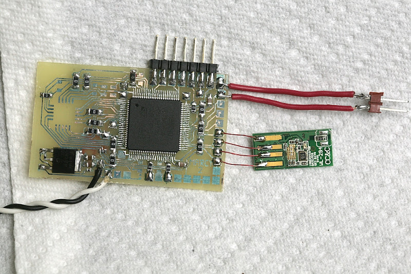
The truth about the STM32 USB core

wifi04.jpg

Manely conrolling a USB device from a microcontroller, something we hated when it was our day job, but now suddenly need.

Also in this issue, home made JTAG is now flashing 3.7kbytes/sec.  The latency is so bad when changing data direction in a USB device, bitbanging the reads in the JTAG protocol is killing us.

Got the ARM up to 168Mhz.   Pretty fast for a home made board & it won't need a crystal to drive the camera.  The GPIOs go to 15Mhz even in software bitbanging.

Because we don't have an external oscillator & the example firmware was written for the Discovery board, which has an external oscillator, it took quite a bit of fussing.  The examples have no settings for the internal oscillator.

Should be noted the STM32 can be bricked if the PLL is misconfigured for over 168Mhz.  JTAG will start timing out in the halt requests & you'll never be able to reflash it.

marcy2_14.jpg


Fortunately, we have some oscillator chips for the camera to drive the ARM at a lower frequency & get it reflashed.  It automatically switches to an external oscillator if one exists.  Those are real tiny oscillators.


Next on our list was the reality of not having a C library.  It's a shame to run such a powerful chip with no C library or math library, but getting those to work requires a lot of trickery & we don't need them yet.

The C library does a neat thing during initialization: copy the compile time initialized data tables to SRAM.  Since we don't have enough SRAM to store data tables, it was easier to just hack around it. 


Do nm arm/copter.elf|sort|less

find everything starting in a d in the source code & change it from static __I to const to get the compiler to store it in flash.


The serial port printf stream has begun.

Welcome to Marcy 2
 HCLK_Frequency=168000000 PCLK2_Frequency=84000000 PCLK1_Frequency=42000000 SYSCLK_Frequency=168000000

The claim of high speed USB on the product matrixes was wishful thinking.  In reality, the high speed mode requires an external PHY.

There are 2 USB cores.  It could theoretically be 2 USB hosts, simultaneously.  1 core does full speed & low speed.  The other core does high speed & full speed, but getting the high speed requires an external PHY.

They're bonded to different pins. The core that does only full speed uses the OTG_FS_DM, OTG_FS_DP pins in the datasheet. The core that does high speed uses the OTG_HS_DM, OTG_HS_DP pins, but since it requires an external PHY to do high speed, those pins can never actually be HS.  They're really full speed, using the core capable of high speed.

Since the Discovery board only uses the FS pins, many #defines & switches have to be hacked in the source code to use the HS pins in full speed mode.  Some of them are labelled FS, some are HS, & some are HS_FS.  Then you need to rename the interrupt handler HS instead of FS, everywhere.

2 more days of hitting a brick wall revealed the USB host had never been successfully used with GCC.  It was getting URB_STALL errors, which caused it to return all 0 for the config return packets & never enumerate.   1 other guy had the same problem & managed to fix it by replacing all the uint16_t_uint8_t unions with uint16_t in the USB_Setup_TypeDef.


GCC aligns structs & unions on 32 bit boundaries.  Don't know how he found that, unless he compared the traffic with a functioning host.  Would be nice if all microcontroller makers just made their stuff work the same way instead of requiring a ground up debug operation for every new chip.

For all the effort we put into using a tried & true, heavily supported code base, it's still more of the same.  Can't remember doing anything that had a tried & true code base.

 
Onward & upward with this operation.


There are some notes about getting the RTL8192 to work as an access point on

http://home.comcast.net/~tomhorsley/hardware/rtl8192cu/rtl8192cu.html


You can be sure the AR drone uses hostapd.


The great debate is whether to port the minimum required sections of the rtl8188 driver to Marcy 2 or create a fake kernel layer to interface the stock driver.  Either solution is bad.  1 way involves porting every new driver that's ever going to be made.  1 way involves emulating a huge amount of software which changes in every kernel release.

Read more…

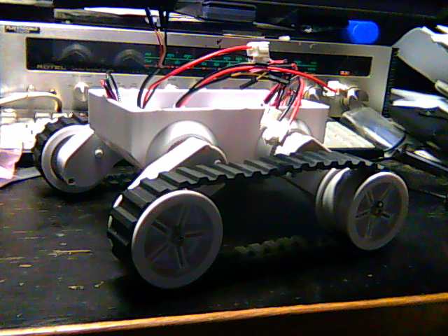
My new UGV in alpha

This is what I've done to my Dagu Rover 5!

As it comes out of the box.

snapshot.pngI was shipped the 4 motor version.

I live out here in the "boonies", so I get to talk to guys that use and maintain earth moving equipment.

There is even a guy that restores old tractors, stationary engines and such.

Talking with them was great, they all said powering a track at BOTH ends was a total waste of time and power.

Most people who get one of these say the tracks are a pain.

The 'dozer mechanic, who is ex-army and worked on tanks, told me that I could expect the thing to "throw" tracks due to

- no road wheels

- being powered at both ends of the track

So I went with the Dagu Wild Thumper wheels, 120mm in diameter.

Straight up it draws less current, that might be due to more mechanical advantage of a larger diameter wheel.

One thing that I don't get is most guys just wedge an Arduino etc and a few batteries in the chassis and call it "done".

Well that's just not good enough!!

I want mine to be a lot more robust.

The other thing is if you have off road wheels, the damn thing should be able to cope with dirt, dust and a bit of water!

So I set about building some chassis mods.

IMG_6119.jpgIMG_6124.jpgIMG_6127.jpgIMG_6131.jpgIMG_6134.jpg

The Controller is a genuine Arduino Mega, with Sparkfun XBee, GPS and Monster Motor Shields.

I have a DFRobot prototyping shield with an LSM303 tilt compensated compass sitting on top of the stack.

The XBee is a Series 1, 60mW XBee Pro with the U.FL to RPSMA conector.

My controller is either another genuine Mega with Sparkfun GPS and Joystick shield or you can use an XBee USB Explorer on a computer.

The steering either way looks like a numeric keypad for steering, with "z","x","c","v" setting the throttle level.

My video link is a digital 2.4Ghz security camera, which has a low-ish frame rate, but plays nice with the 2.4Ghz Xbee.

I have a pair of 900Mhz XBee Pro's for when I go to an analogue video link.

Here is some video showing the onboard equipment and some "on patrol" video.

https://www.youtube.com/watch?v=43zqBtQyBF0

https://www.youtube.com/watch?v=iUs2frHb6qk

https://www.youtube.com/watch?v=JIyQP_YWDto

Read more…
Developer

Aircraft saved by MinimOSD

I just got this video from André Kjellstrup.
It shows the importance of an OSD with instruments in hard FPV flight conditions.

From his own words: "lost visual far out over water when a sudden and passing snow shower with wet, heavy snow clogged lens". Fortunately his craft was equiped with ArduPilot Mega and MinimOSD. ;)

Here is an earlier video from André who is always giving us his feedback.

Thank's by your nice videos André!

Read more…
3D Robotics

FPV with the AR.Drone with head-up display

The Epson Movereo BT-100 is an Android-powered transparent video goggle, with interesting hacking potential. This 16-year old kid decided to show what they can do by flying an AR.Drone in FPV mode.


From Engaget

These shades have dual transparent lenses with 960 × 540 qHD resolution bringing you video in three dee, while audio is doled out by built-in earbuds with Dolby Mobile technology. Content is accessed via a Froyo-powered control unit equipped with 802.11b/g/n WiFi and 1GB of internal memory, plus there's an SD card slot (4GB card included) for storing media. Navigation and control comes courtesy of the controller's touch-sensitive trackpad and dedicated Android buttons, a 2D/3D toggle switch, and d-pad. The BT-100 will be available in Japan come November 25th for ¥59,980 ($771 US), but those interested in importing one can get all the device's juicy details at the Source links below.


The Verge explains the hack:

16-year old hacker and programmer Thomas Sohmers is working on a project that lets you control a Parrot AR Drone quadrocopterusing the head-mounted display and its handheld controller. Sohmers' app connects to the Parrot through Wi-Fi, letting you both control its movement and see through its cameras. This means that you can look through the drone's front-facing camera while flying, and then the bottom-facing one while landing, while still being able to view the copter itself. There's still some work to do on the controls — right now you can only control the rotation and vertical movement — but cool applications like this at least provide an extra excuse to don the bulky BT-100.

Read more…