All Posts (14049)

Sort by

QUADROTOR CHIPKIT MAX32

3689496170?profile=original

The project is to develop a PID controller for a quadrotor, using the fabulous machine max32 board  the Company DIGILENT    with 32-bit resolution, to implement not only linear control strategies such as PID control strategies as well as RREE nonlinear (feedback state space ) and SMC (sliding mode control).

Using as the fabulous imu sensor 9 DF Sparkfun Razor Company.

IMU

3689496295?profile=original


https://www.sparkfun.com/products/9623

3689496318?profile=original

MAX32
http://www.digilentinc.com/Products/Detail.cfm?Prod=CHIPKIT-MAX32

proyect max32

https://github.com/elkintomen/Fivacopter_MAX32

videos

https://www.youtube.com/watch?v=VxjcwZDZQ4o

https://www.youtube.com/watch?v=-NV9T4hCmtc

Read more…

My first time off the ground.

8248903811_8e91fe7e91_z.jpg

I saw another post this morning from someone in NC with a hex, so I figured I'd post a little about my first quadcopter build as I'm in NC too.  I started off building the frame inspired by the 3DR design but made my own arms and legs.  I made taller legs in order to mount an old iPhone 4 I had laying around under it for video recording. 

Here's a couple of pictures from the build and then some video of the first time getting it in the air.  I have had no prior RC aircraft experience.

8315142440_c7c91e22d6_z.jpg

So after a couple of months of reading, collecting parts, purchasing an APM 1.4 and 2.5 (don't ask, wanted to play with both old and new I guess), I made the first couple of test flights using the 1.4

And after adding the iPhone to the mount I built, the second flight had onboard video

It's been amazingly fun so far, I think I like making the parts I made to substitute the kit parts the best and have already gotten into redesigning my legs and camera mount, more to come...

Read more…

USAV - An architectural update + video

3689493597?profile=original

Here's an update on the USAV project I started some months back. This post is mostly about the architecture and features of the current version as well as a video of a static test.

The USAV is a UAV with an integration to some of the social networks like twitter and Google talk. It is also an android powered guidance system currently implemented in a standard 450 flame wheel quad copter.

So it's been a while since the last post about the USAV - although slowly, things has progressed mostly on the software side although the quad itself has been upgraded with a new frame and the KK2.0 from Hobby King (and downgraded again - longer story).

Denmark is a cold and wet kind of place especially during winter and is certainly not ideal for anything that's electric, (a bit) fragile and is preferred to be operated outside. So my last flight with the USAV was in September where the craft suffered a near death experience (one engine and IOIO board did experience the real thing). From then till now, I've spent my time on rebuilding and adding features to the software.....oh, and I also became a father :)

Today I would like to give some insight in the project as well as a little video of how you interact with the craft.

The software

As mentioned, the brains of the craft is implemented on the on-board Android based cell phone. The software is written as a java based app. The main building stones of the app is as shown above.

As you can see, the typical smart phones features such as internet connection, GPS, compass, accelerometers and camera are all being utilized giving the "brain" a lot of interesting possibilities during flight.

The system allows you to manually control flight by chatting with the craft during flight, as well as set a route through waypoints and let the auto pilot, in turn, guide the craft to the individual waypoints. Each waypoint can have some extra characteristic, such as;

pause

loiter

follow (A special type of way-point that moves ie. another smartphone broadcasting it's GPS coordinates)

Way-points can be created either by specifying GPS-coordinates or by address. A return point is automatically added to the flight manifest to ensure that the craft returns to the starting point.

The auto pilot part is as of now very simple - utilizing the GPS and compass to determine where the craft is in relation to the current waypoint, and executing commands to get closer.

3689493766?profile=original  

Sometimes, when you develop software, you tend to model the real world as much as possible. Sometimes this makes perfect sense, but in the terms of the auto pilot, I choose a different approach.

A real world pilot is very specialized in his knowledge of the craft has is piloting, i.e. an aircraft pilot may not now how to pilot a helicopter or in principle a car for that matter.

This software pilot is created (like many other auto pilots) so that it doesn't know any specifics about the craft it pilots and can therefore be used with all kinds of crafts (cars, boats, planes and helicopters). The autopilot relies on a stack of modules that can translate the pilots direction commands to something specific for the particular craft as shown below.

3689493853?profile=original

The clever thing about this being that new crafts and control boards can be implemented quickly through java interfaces.

Current features highlight

Okay so where are we right now in all this - to put it short, I have a lot of code and very few flying hours (minutes actually), so there are a lot of untested features. So far tests has been mostly focused about communicating with the craft and doing some basic maneuvers. Since I am new to the wonderful drone world, this has been a slow and very google/diydrone driven development cycle and I'm sure there are a lot of obstacles yet to be solved.

A selection of the current features I have implemented are;

Setup

* Speech Synthesis feedback

* Way-points are added using gtalk

* Street address to GPS coordinates

Autopilot

* Range safety (abort mission if flight path becomes too long)

* Timer safety (mission abort after xx seconds)

* Auto return to starting point

Flight

* Soft throttle (changes throttle gradually - saves on props and motors)

* Calculate distance traveled / remaining in real time

* Auto land using accelerometers

* Logging of flight data

* Kind of accurate altitude calculation using GPS 

Social

* A large set of gtalk commands

* Twitter integration (text and camera pictures)

Command set

Using gTalk, these are the current commands implemented

3689493810?profile=original

Below is a video demonstrating some basic features in a static test. A bit dull I'm afraid, but at least you'll get an idea on how you interface with the USAV.

When the weather allows I will take the craft for a flight and will surely need your advice on tuning the controller for the most stable and efficient flight.Currently i'm using xcopter firmware 1.1 - Should I change to KapteinKuk 4.7?

Best regards

-Jesper A

Read more…

H-Quad Part 2

3689496234?profile=original

Here's where I am so far on the H I started before the holidays. Ended up trimming the arms and drilling out some of the plates to lessen the weight. Will likely add some CF rods as prop protection during the tuning process.


Using 10x4.7 props for now, though the motors could handle larger. Testing has it hover at just under 50% throttle, so I think I am in a good place. Not tuned yet - that's next when the rain lets up.


The APM is enclosed in a very stylish $0.99 plastic box from Office Depot. The stack sits on a fiberglass plate attached to the body plate with 3M double sided foam squares. The lid of the box is velcroed to the FG plate and the APM is velcroed to the lid. The bottom of the box forms the cover for the stack and clips on.

3689496280?profile=original


Still need to rig up battery straps, the external LEDs for GPS and arming indicators, some running lights, a GPS enclosure, and general cleanup.


Read more…

Homemade Steadycam Hexacopter

3689496203?profile=original

This is my project, I have been working on it for a couple of months. Is not ready yet and certainly it's not good looking, need more work but here is a video of some features.

Note this is a Steadycam design based on ECILOP ideas. But with a Multiwii board instead of gyros. Multiwii is fixed to the steadycam arm and acts as stab controller. I did a couple of changes in multiwii firmware to add a new mode "STEADYCAM" couse "GIMBAL" mode is just delta angle stab, and I need a PID loop stab + delta angle.

I use high speed servos and rubber bands as actuators couse direct drive is a mess.

The inner frame is connected to main frame by rubber band, so vibration cant pass trough to the FC and Steadycam system.

Here are the arms and main frame:

3689496151?profile=original

 3689496154?profile=original

Fully assembled, note that no camera is attached bellow, instead a use a dead lipo battery as ballast and my bike back light which has a laser similar to a laser level.

3689496203?profile=original

https://www.youtube.com/watch?v=Y77qXdy_l1E

Read more…
3D Robotics

3689496075?profile=originalI was hoping for GPS navigation, to make it a real drone, but we're going to have to settle for GPS logging for now.

From Mashable:

LAS VEGAS — Parrot's popular AR. Drone quadcopter will be getting some major improvements this year with the rollout of GPS tracking, longer battery life, better steering and revamped video recording capabilities.

That seems like a lot to cram into a new reiteration of the AR. Drone 2.0 prototype that is on display at the 2013 International Consumer Electronics Show, but a demo conducted for Mashable on Sunday revealed the update is really something for fans to get excited about.

With promises for a launch "sometime this year," Parrot said the new battery will allow the quadcopter to fly for 18 straight minutes — six minutes longer than its current flight time. The battery will be available as an upgrade purchase (price to be determined), and it will come with the new model as well.

"We extended the battery because it's something a lot of people asked for," a Parrot spokesperson said.

It will also tout a GPS "Flight Recorder," which is a GPS receiver with 4GB flash memory that records flying perimeters. This means you can visualize your flight route on the map flights in 3D. It's also shareable with others.

The accompanying app, which is used to steer the device, will also get an update. A new feature called "director mode" will give more control to steering with the help of pre-registered and automatic movements. This is a huge improvement over the current model, where movement and turns are often bumpy and hard to control. Instead of moving your mobile device from one side to another, you will be able to hit a button to make it move forward, stop abruptly, turn around and pan. It also makes shooting videos easier to stabilize, and editing tools allow you to clean up shaky shots and colors.

The app games AR.Race 2.0 and AR.Rescue 2.0 — which allow you to race with others — will also be revamped to reflect the latest updates.

Read more…

New ArduCopter Hex flying in NC

This is the second flight of the Diydrones Hexcopter. I`m using two 3S-2250mah batties ganged together untill the new 3S-5000mah packs show up in the mail. Using a JR 11X and a Spektrum 9 channel receiver. I had to link up the mission planner on the desk top because the two older laptops would not work. I still have to figure it out.   I found that the hex is not too hard to fly, maybe because I have some experience with RC helis. I still have to add the different flight modes.    http://youtu.be/7TAIk5SqdAA  http://youtu.be/uiPbJueQ-Jk

Read more…
3D Robotics

Humanoid Hexacopter

Love the arm and leg animations!

From Robot Dreams:

The Robot Japan events get better and better every time. Last weekend the 5th semi-annual competition was staged drawing a large audience, numerous participants, and an impressive contingent of Korean robot builders including Robot Factory. One of the most crowd pleasing demonstrations at Robot Japan was a hexcopter equipped with a fully functional Tiny Wave humanoid robot. Although there are no official plans, it was easy to imagine this evolving into a ROBO-ONE in the Clouds battle sometime in the near future.

Read more…

My first Quadcopter Build

3689496005?profile=original

Hello everyone, having not been into RC since I was a young lad, with a little persuasion from a friend I decided that I would begin a quadcopter project. Due to being married my project spend will be over the course of 4-5 months. I have broken my build down into several phases. This also gives me time to do some reading, watch youtube vids on setups and performance, create blog posts and keep a build log. So far its been an interesting learning experience with a few mistakes and purchase regrets along the way. Based on the below setup should get approx 20-30 min max flight time with hover time around 150min. Possibly after a while I may save up and buy some lower rpm tiger motors to increase flight time sacrificing manoeuvrability.

Phase One

Assemble Turnigy Talon V2 frame

T-Motors MT2216 900kv Motors

10*4.5 carbon reinforced nylon props

xbee telemetry kit

Phase Two

T-Motors 30/40A ESC

T-Motors ESC programming card

Bullet and XT60 connectors

Turnigy Power Distribution Board

Phase Three

Arduino Pilot Flight Computer

GPS, Airspeed, sonar, barometer and optical flow meter

Phase Four

Lipo battery charger

two turnigy nano tech 8400mah 3s2p lipo

turnigy 9x 9channel 2.4hz RC controller

Phase Five

Programme Xbee telemetry speed
Solder connecitons to power distribution
Programme ESC
Program board latest firmware
Set limits and write to board
Write up pre-flight checklist
Final Assembly
Calibrate RC controller
Prop setup test
Arm-disarm test
First test flight
Fine tuning
APM Auto-trim setup
APM Mode setup

Other interim tasks

Build Log

Build Custom Gimble using carbon fibre (salvaged from carbon fibre golf umbrella)

Any advice, comments welcome. Links to sites and youtube vids to follow.

Read more…
3D Robotics

ArduRover launches ArduPlane!

Check out today's awesome demo by Tridge. An ArduRover launches an ArduPlane! (Also note that the ArduPlane is flying beta ArduPlane software on the PX4 board. We're getting close to a dev release on that. Very exciting...)

[UPDATE] Tridge adds some details in the comments:

The SkyFun was in FBWA mode, with throttle off until after it lifted off the rover (the prop was resting on the APM on the rover, so zero throttle was important!). Both the rover and skyfun were running current APM git master. The SkyFun was using a PX4FMU board running the NuttX port of ArduPlane. Today was our first test flights of ArduPlane on the PX4, and it flew very well. Flight logs from today are here

The camera was being operated by our youngest club member Marias, who just got his MAAA gold wings today.

The reason we were doing this was to test the concept for possible use for launching our X8. We've found that hand launching the X8 with a heavy load on board is quite dubious, so we've mostly been using a bungee, but we thought a rover launch would be fun. Today was a test run with the SkyFun.

We've also built a catapult system for the X8 which we have yet to test.

Read more…

DIY UxV control station - DRAFT

newtx.png

This project currently is in draft status. I will update the article on my homepage, as it progresses.

Normal R/C transmitters are not the best way to control a UxV. For instance, they usually require additional components like ArduStation for the ArduPilot project, which means, the operator has to start juggling already with 2 components. Depending on mission and payload, there easily might be 1 or 2 more systems added. Based on this idea, I started thinking about a UxV controller which at least inconporates the R/C transmitter and the mission control component.

The R/C TX component is based on modules. I am planning to use the FrSky DHT module which is especially for integration in user projects. Another possible option would be to cut a matching rectangular hole into the UxV-CS' enclosure e.g. for JR compatible modules. The main board could be taken from a cheap chinese radio, e.g. the Turnigy 9x, but I am planning for the ERSKY9x board. The ERSKY9x board is a third party board which was developed as an improved replacement board for the 9x radios. It features a much more powerful CPU and runs Open9x firmware.

Instead of the usual R/C-joysticks, the UxV-CS will have 3-axis joysticks which pushbuttons. Additionally, a linear slide potentiometer and several switches are planned on the TX side.

The mission control component will be based on an Arduino Mega 2560 with a 40x4 character LC-display. The Arduino will feature  "softbuttons" with changing functions as well as a 4x4 matrix keyboard for data entry. Those will be complemented by mission-related switches and an external joystick module for camera operations. Also, a mini thermal printer will be integrated e.g. for adhoc printing of GPS coordinates in SAR missions. For communications, the 3DR 433MHz modules are planned.

Update 07JAN13, 1610UTC:
- Corrected some typos
- Updated link to project page
- Added reference to 3DR radio modules

Read more…

Kalman Filter Code for Yellow Plane 2

Kalman Filter Code for Yellow Plane 2 Special thanks to Kristian Lauszus, TKJ Electronics 

IMG_2221.JPG

This is the code in the main loop UpdateServos()

<code>

unsigned long msDelta = LastMicros - micros();
LastMicros = micros();

//Measure time since last cycle
double dt = (double)msDelta / 1000000.0;


// The angle should be in degrees and the rate should be in degrees per second and the delta time in seconds
double X_Angle = (double)AnIn[0];
double X_Rate = (double)AnIn[4];
double Kalman_X = kalman[0].getAngle(X_Angle, X_Rate, dt);

double Y_Angle = (double)AnIn[1];
double Y_Rate = (double)AnIn[5];
double Kalman_Y = kalman[1].getAngle(Y_Angle, Y_Rate, dt);

double Z_Angle = (double)AnIn[2];
double Z_Rate = (double)AnIn[6];
double Kalman_Z = kalman[2].getAngle(Z_Angle, Z_Rate, dt);

</code>

kalman.h can be downloaded here

<code>

/* Copyright (C) 2012 Kristian Lauszus, TKJ Electronics. All rights reserved.

This software may be distributed and modified under the terms of the GNU
General Public License version 2 (GPL2) as published by the Free Software
Foundation and appearing in the file GPL2.TXT included in the packaging of
this file. Please note that GPL2 Section 2[b] requires that all works based
on this software must also be made publicly available under the terms of
the GPL2 ("Copyleft").

Contact information
-------------------

Kristian Lauszus, TKJ Electronics
Web : http://www.tkjelectronics.com
e-mail : kristianl@tkjelectronics.com
*/

#ifndef _Kalman_h
#define _Kalman_h

class Kalman {
public:
Kalman() {
/* We will set the varibles like so, these can also be tuned by the user */
Q_angle = 0.001;
Q_bias = 0.003;
R_measure = 0.03;

bias = 0; // Reset bias
P[0][0] = 0; // Since we assume tha the bias is 0 and we know the starting angle (use setAngle), the error covariance matrix is set like so - see: http://en.wikipedia.org/wiki/Kalman_filter#Example_application.2C_technical
P[0][1] = 0;
P[1][0] = 0;
P[1][1] = 0;
};
// The angle should be in degrees and the rate should be in degrees per second and the delta time in seconds
double getAngle(double newAngle, double newRate, double dt) {
// KasBot V2 - Kalman filter module - http://www.x-firm.com/?page_id=145
// Modified by Kristian Lauszus
// See my blog post for more information: http://blog.tkjelectronics.dk/2012/09/a-practical-approach-to-kalman-filter-and-how-to-implement-it

// Discrete Kalman filter time update equations - Time Update ("Predict")
// Update xhat - Project the state ahead
/* Step 1 */
rate = newRate - bias;
angle += dt * rate;

// Update estimation error covariance - Project the error covariance ahead
/* Step 2 */
P[0][0] += dt * (dt*P[1][1] - P[0][1] - P[1][0] + Q_angle);
P[0][1] -= dt * P[1][1];
P[1][0] -= dt * P[1][1];
P[1][1] += Q_bias * dt;

// Discrete Kalman filter measurement update equations - Measurement Update ("Correct")
// Calculate Kalman gain - Compute the Kalman gain
/* Step 4 */
S = P[0][0] + R_measure;
/* Step 5 */
K[0] = P[0][0] / S;
K[1] = P[1][0] / S;

// Calculate angle and bias - Update estimate with measurement zk (newAngle)
/* Step 3 */
y = newAngle - angle;
/* Step 6 */
angle += K[0] * y;
bias += K[1] * y;

// Calculate estimation error covariance - Update the error covariance
/* Step 7 */
P[0][0] -= K[0] * P[0][0];
P[0][1] -= K[0] * P[0][1];
P[1][0] -= K[1] * P[0][0];
P[1][1] -= K[1] * P[0][1];

return angle;
};
void setAngle(double newAngle) { angle = newAngle; }; // Used to set angle, this should be set as the starting angle
double getRate() { return rate; }; // Return the unbiased rate

/* These are used to tune the Kalman filter */
void setQangle(double newQ_angle) { Q_angle = newQ_angle; };
void setQbias(double newQ_bias) { Q_bias = newQ_bias; };
void setRmeasure(double newR_measure) { R_measure = newR_measure; };

private:
/* variables */
double Q_angle; // Process noise variance for the accelerometer
double Q_bias; // Process noise variance for the gyro bias
double R_measure; // Measurement noise variance - this is actually the variance of the measurement noise

double angle; // The angle calculated by the Kalman filter - part of the 2x1 state matrix
double bias; // The gyro bias calculated by the Kalman filter - part of the 2x1 state matrix
double rate; // Unbiased rate calculated from the rate and the calculated bias - you have to call getAngle to update the rate

double P[2][2]; // Error covariance matrix - This is a 2x2 matrix
double K[2]; // Kalman gain - This is a 2x1 matrix
double y; // Angle difference - 1x1 matrix
double S; // Estimate error - 1x1 matrix
};

#endif

</code>

The Arduino code originally written by Kristian Lauszus, TKJ Electronics can be
downloaded here

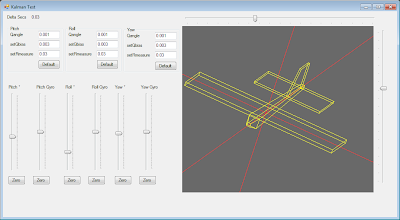
I have a test harness written in C# there is a C# version of the Kalman Filter class which could very easyly be addapted for use with Fex Panda or Netduino Tiny CLR projects

The C# code for the test harness shown below can be downloaded here 

kalman+test.png?width=640

The above could be modified to accept input from a IMU or Accelerometers and Gyros

3689495868?profile=original

3689495969?profile=original

Read more…

Thermal Imaging Tests on Conservation Drones

Over the last week, ResearchDrones.com and ConservationDrones.org conducted a series of tests of low cost thermal imaging cameras.

Models tested:
1. FLIR HS-324 Patrol 19mm Thermal camera (320 x 240 res) (link)
2. NEC F30 Thermal Shot Infrared Thermal Imager (160 x 120 res) (link)

Above: Flight tests (cloudy daylight, ~3 pm winter afternoon)

FLIR image taken by conservation drone from ~100 m above ground. FLIR camera tilted ~40 degrees downwards.

FLIR image at 100 m above ground.


NEC image taken by conservation drone from ~100 m above ground. NEC camera was downward facing.

NEC image at 100 m above ground.


Ground tests (complete darkness, ~9 pm winter night):

Conclusion:

The FLIR is the clear winner in terms of picture resolution and thermal sensitivity. But the FLIR HS-324 is also much heavier and costly (~600 g, ~US$ 7,000) than the NEC (~300 g, US$ 4,000).

Based on these tests, we believe the ideal solution might be the more compact FLIR MS-324 (320 x 240 res) (link), which has the same resolution as the FLIR HS-324, but weighs much less (340 g) and is also more affordable (~US$ 3,000).

(*Note: We are not sponsored by the companies hyper-linked to in this post. The cameras we tested were either rented or on loan from colleagues.)

Read more…


3689495698?profile=original


I came across this while researching wireless solutions and seems very possible to create a long range WiFi connection between the GCS and aircraft using an onboard micro computer.

These are the specs that the company boasts:

--------------------------------------------------------------------------------

Processor Specs: Atheros, 6th Generation, AR5414

Radio Operation:  Proprietary 900MHz

Interface:  32-bit mini-PCI Type IIIA

Operation Voltage:  3.3VDC

Antenna Ports:  Dual MMCX

Temperature Range:  -45C to +90C (extended temp version up to +95C)

Security:  802.11i, AES-CCM & TKIP Encryption, 802.1x, 64/128/152bit WEP

Data Rates:  6Mbps, 9Mbps, 12Mbps, 24Mbps, 36Mbps, 48Mbps, 54Mbps

TX Channel Width Support:  5MHz / 10MHz / 20MHz / 40MHz

RoHS Compliance:  YES

Avg. TX Power:  28dBm, +/-1dB

Max Current Consumption:  1.10A, +/-100mA

Indoor Range (Antenna Dependent):  over 400m

Outdoor Range (Antenna Dependent):  over 50km

Operating System Support:  Linux MADWIFI, WindowsXP, Windows2000

Advanced Mobility / Quick Handoff:  WindowsXP/2000 Utility with Enhanced Mobility Driver from Ubiquiti

Cisco Support:  CCX 4.0 Supported Driver/Utility also available from Ubiquiti

------------------------------------------------------------------------------------------------------------------

They also carry ones for the 5GHz and 700MHz frequency range.  If anyone has ever used these or could see a possible usage in a UAV, please comment!


Hunter

Read more…

Configuring Turnigy 9x with arducopter

3689495931?profile=originalManual

There had been two blogs regarding configuration of Turnigy 9x with APM but i had experienced difficulties in them. So here i am, writing my own experience.

I am using the Turnigy 9x Mode 2 with RF 9X v2 2.4GHz module and 8 channel receiver but the same applies to Mode 1 as well.

About Turnigy 9x: I think they are good for their price. They provide almost all the functionality needed for APM.

The package contains a controller with the transmitter module installed, a 8 channel receiver and a binding wire which can be used for paring other receivers or transmitters ( i haven't tried that.)

Following is the connection list between turnigy receiver and APM.

Receiver       APM

1                    1

2                    2

3                    3

4                    4

5                   Not connected

6                   5

7                   6

8                   7

PWR            PWR

GND            GND

Goto menu->System settings and Type Select. Select Acro

                                                      Stick Select  Mode 2 ( Mode 1 users select mode 1)

Goto menu-> Function settings, goto second page and select Aux Channel

Assign CH5 to Gear and Channel 8 to THRO HOLD.

DON'T ASSIGN CHANNEL 6 TO ANYTHING. IT MUST BE LEFT NULL.

Open Mission Planner after connecting APM (connected to receiver as mentioned above) via USB. Goto Configuration and then Flight Modes. Configuring the F Mod switch will require us to read the PWM. We don't need anything other than the mission planner. The PWM reading can be taken on the Current PWM.

The PWM ranges for different flight modes are also shown on the same APM window. We need 1165 for Flight mode 1, 1295 for flight mode 2, 1425 for flight mode 3, 1555 for flight mode 4, 1685 for flight mode 5 and 1295 for flight mode 6. It is not required to get these exact values. The values for flight mode 2-5 are the mean of the range values. You might not get the exact values, select a value closer to these.

Set the F Mode (AUX 3) Switch at N (top position) and Gear to rear on the controller.

On page 2 of the controller menu, select Prog Mix

Goto Mix 1, change status to ACTIVE, Master to GYR and Slave to FLP, SW to NOR

Change  the DNRate parameter until you get 1165. (mine was 075)

Now change the Gear switch to front.

Change the UPRate parameter until you get 1295. (mine was -044)

Press menu to save changes.

Change the F Mode switch to 1 and Gear switch to rear.

Goto Mix 2, change status to ACTIVE, Master to GYR and Slave to FLP, SW to ID1

Change  the DNRate parameter until you get 1425. (mine was 013)

Now change the Gear switch to front.

Change the UPRate parameter until you get 1555. (mine was 019)

Press menu to save changes.

Change the F Mode switch to 2 and Gear switch to rear.

Goto Mix 3, change status to ACTIVE, Master to GYR and Slave to FLP, SW TO ID2

Change  the DNRate parameter until you get 1685. (mine was -049)

Now change the Gear switch to front.

Change the UPRate parameter until you get 1795. (mine was 076)

Press menu to save changes.

Exit the menu and toggle the switches to see the flight modes change in the same APM page.

Flight Mode 1: F Mode switch at N and Gear switch to Rear

Flight Mode 2: F Mode switch at N and Gear switch to Front

Flight Mode 3: F Mode switch at 1 and Gear switch to Rear

Flight Mode 4: F Mode switch at 1 and Gear switch to Front

Flight Mode 5: F Mode switch at 2 and Gear switch to Rear

Flight Mode 6: F Mode switch at 2 and Gear switch to Front

We have sacrificed channel 6 for getting six flight modes. Channel 6 is usually used for tuning. Once tuned, i don't think we need channel 6 then. In order to use channel six for tuning, disable MIX 1, 2 and 3 by changing their status to INH. You don't need to vary any other parameters. Goto CH_AUX and assign

CH5 => Gear

CH6 => PIT_Trim

CH7 => Throttle Hold

You can tune on channel 6 then using the PIT TRIM potentiometer on the controller. Once tuned, change back the CH_AUX as mentioned before and enable the MIX 1,2 and 3.

Adjusting controller inputs sensitivity ( Limiting the controls)

There are three toggle switches with labels Rud D/R, ELE D/R and AIL D/R.

these switches have two positions, 0 and 1.

They can be used to vary the range of the inputs during the flight. By default they are -100% to 100%. You can change them to e.g. -50% to 50% and can be changed during the flight with the D/R switches if desired to have a sensitive control.

D/R switch at 0 => Limited control

D/R switch at 1 => Full control

By default these switches are disabled, in order to enable them, goto menu on the controller, func settings and select D/R EXP. Change between the channels by changing the CH to RUD0, ELEV and AILE.

Change the D/R limit to whatever you want to be the limited control input ( control channel output is limited from the controller even if fully deployed. Can be changed to full by changing the D/R switch to 1 on the controller)

You can see the response on the D/R Expo page on the controller by setting the limit D/R and toggling between corresponding D/R switch on the controller.

Press Menu to save changes.

Reversing the pitch stick. You also have to reverse the pitch stick to get pitch down with pitch stick forward and pitch up with pitch stick back.

Arming/Disarming Issue with the D/R at RUD0. Arming and disarming requires full rudder to the left and right i.e. 100% (not limited). So it won't arm/disarm if the RUD0 is limited and the D/R RUD is at 0. Either don't use this D/R limit on RUD0 or remember to put the D/R Rud at 1 while arming / disarming.

The controller has a timer functionality which can be used to start the timer at the start of the mission, and the timer will start beeping with each second in the last minute to warn about the end of timer. This timer must be set considering the endurance of the arducopter. The timer can be set in the TIMER in the Func Setting in the controller menu. Once set, the timer can be triggered with the TRN switch at the back of the Gear switch. The timer can be paused by the same switch. In order to reset the timer, you will have to restart the controller. (Make sure APM is disarmed in case it is configured for throttle failsafe)
Read more…
3D Robotics

3689495911?profile=originalThis used a car, not a drone, but it's a nice example of datalogging and data merging. With a drone you wouldn't be limited to plotting cell sites along roads. 

From the Google Earth blog:

Franz Graf knew he had a shaky mobile connection on his daily commute, but wanted to see just how bad it was. To find out, he wrote an Android app that recorded the GPS position and signal strength along his journey and then plotted all of the data in Google Earth. The result is a great Google Earth KML that shows cell tower strength in his area:

The image above was created with approximately 9,000 data points from his commute. He plans to release the app to Google Play so that others can use it, which I would love to download to drive around my area and see how it does. I have some idea of where the dead zones are, but this would give me a more concrete look at it.

He's released a sample KML filegelogoicon.gif so you can see first-hand how the output looks.

You can read more in his original post on Google+, and then the follow-up post where he plotted it in Google Earth. If he releases the app for others to download, we'll certainly let you know about it.

Read more…