Down from original model's price of $399.
Added:
- waterproof housing
Removed:
- Removable battery
- GPS
- Bluetooth
- HDMI
Down from original model's price of $399.
Added:
Removed:
MAKE Magazine founder Dale Dougherty just posted on his visit to the 3D Robotics/uDrones factory in Tijuana. He also spoke at the Tijuana Innovadora conference that I'll be speaking at tomorrow. Other speaker today included Jason Short, one of the core ArduCopter devlopers, and Mark Hatch, CEO of TechShop.
Hit the link above for the whole post, but here are some pictures from it. Above: ArduCopter quads (top) and hexa (bottom) ready for shipping.
TJ operations direction Guillermo ("Gigio") Romero (center) and some of the production team
Jason Short checks out his new black APM 2.5 board!
Special black APM2.5 boards (signifies that it was made on the new 3DR pick-and-place line in TJ)
The PX4Flow smart camera board will be released in a few weeks (designed by ETH, manufactured by 3D Robotics). There will be a ROS library to drive it, along with the PX4 libraries, Lionel Heng from the ETH Computer Vision and Geometry site announced on the ROS news site:
I would like to submit a new repository for indexing: https://github.com/cvg/px-ros-pkg
This repository currently contains a ROS package for interfacing to the soon-to-be-released PX4Flow optical flow board (coming soon from 3D Robotics). We have plans to add a ROS interface to the PX4FMU autopilot, and software for MAV autonomy as showcased in our recent IROS paper (http://www.cvg.ethz.ch/MAV ) in the coming weeks ahead.
Best Regards, Lionel Heng
http://www.ros.org/news/2012/10/from-lionel-heng-of-the.html
Why we wanted HeX at the first place?
1. We wanted it to be able to tackle the contradiction between small aircraft’s size and carriage capacity
2. we wanted it to be omnipotent to accomplish various advanced tasks as human’s replacement in circumstances where human being is incapable.
That resulted in 3 features in HeX : modular design, flexible to peripherals and an open platform of robotic aircraft for hackers.
We thought HeX with the 3 prominent features would be able to cover a wide range of demands in market.
To well demonstrate its potential to wow people in various fields, we decided to make it an air filming kit for outdoor activity fans which can track and film the target automatically and can be used as simply as clicking some buttons
A Change of Strategy
But almost 1 month ago, we had a meeting and made some strategic changes after that. During the meeting, we broke down the logic order of why we want HeX and reviewed the technological and engineering complexity. After rounds of passionate and inspiring discussion, we found what made us really go nuts about HeX was not other features but the very first one: its portability and capacity adaptability given by a modular design, and the use as an air filming kit which might bring revolution to personal and family entertainment.
Before we made a change to our market and development strategy, we went through some technological possibilities:
1. whether ARM can be fast enough to run an tracking algorithm as an airborne computer
2. whether existing tracking algorithm is sophisticated enough to give HeX a stable performance when it is tracking and filming the target in the air
Finally, we decided to temporarily abandon the idea of making HeX an open platform of robotic aircraft. We temporarily don’t want it to be able to carry various different peripherals.
We just want it to be an all-time awesome and portable air-filming kit because personal and family entertainment is already a huge enough business and the market of it is massive.
Now the new born HeX is going to be an portable air-filming kit. It’s going to be revolutionary to both robot-making world and personal-entertaining world.
We took our FPV equipment, put it on a balloon, and sent it up in tandem with Felix Baumgartner. I'm low on sleep and I'm dealing with News on running the story now but here are some cool pics and basics. I'll post more as I can tomorrow, but there's a lot more info on our QuestForStars Facebook page.
1. ServoCity: Using the pt785/985 hybrid to move 1.2ghz 13db yagi and 23cm/33cm 14.5dbc Antenna
2. EagleTree: OSD Pro and Elogger, and Eagleeyes
3. GPS: dual Venus 10hz and Byonics GPS4
4. Numerous cameras and a student X-ray experiment for a NASA rocket contest
>> I think we have quite possible set the distance record for FPV video TX/RX. We flew to 98K feet and a slant range of 85miles before losing video. Basic home wire Dipole hanging under the payload.
>>You can see the liftoff and a good portion on youtube. We now realize that venus is high affected by a 1.2ghz xmitter and we'll need a filter on it the VTX to keep Venus happy. Oddly enough it finally locked but with no GGA.
Pics and more info here.
Time for some sleep--adrenaline from less than 2hrs of sleep a night since friday starting to take a toll. I'll be back tomorrow. Enjoy
This WallChart.pdf is a first draft of an idea to provide diagrams of the relationships between the different modules of any Arduino drone project that new users can stick on the wall.
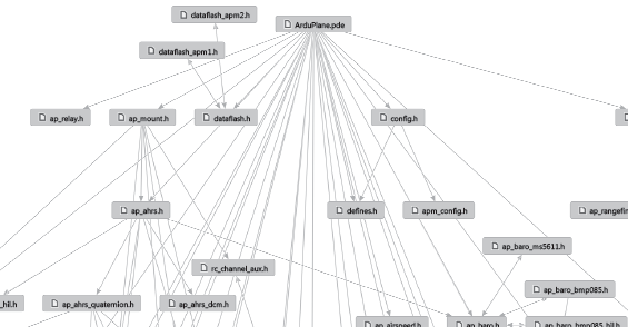
The pdf shows a map of how the various parts of the ArduPilot program interlink. You will see that currently the code diagram is very busy. How could all this information be presented in a more structured manner in a single snap-shot?
How to Create Your Own Code Diagrams - ArduPilot Example
If you have Window XP or Windows 7 then you can easily create your own code diagrams using the Arduino plugin for Microsoft Visual Studio Professional .
The plugin is free, you can read how to get a free legal copy of Visual Studio Professional from here.
1. Open ArduPilot.pde or (.ino) in Visual Studio and right click anywhere in the code.
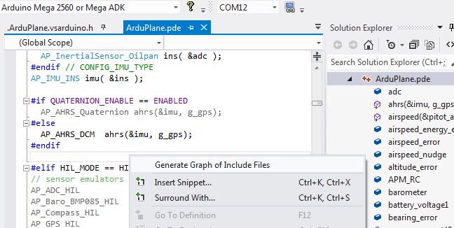
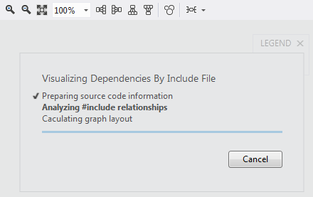
2. Visual Studio will open a new code window containing the diagram explorer tool. Progress will display while the code diagram is being automatically created.
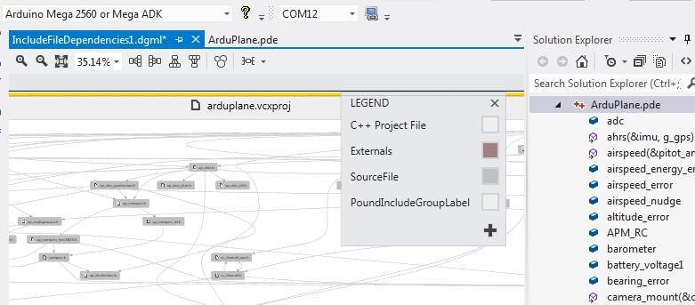
3. The code diagram will automatically appear when the visualization is complete. If required, you can edit the diagram, change the layout and remove items by using the mouse or diagram toolbar controls
About Arduino Compatibility in Visual Studio
Visual Studio is a simple installation and provides 100% Arduino compatible compile and upload combined with intellisense and code explorer tools.
If you are unsure how easy the plugin is to use then you can read what users have to say in the What do you think section of our forum. If you have been using the plugin for a while then please then please support the product by joining the forum.

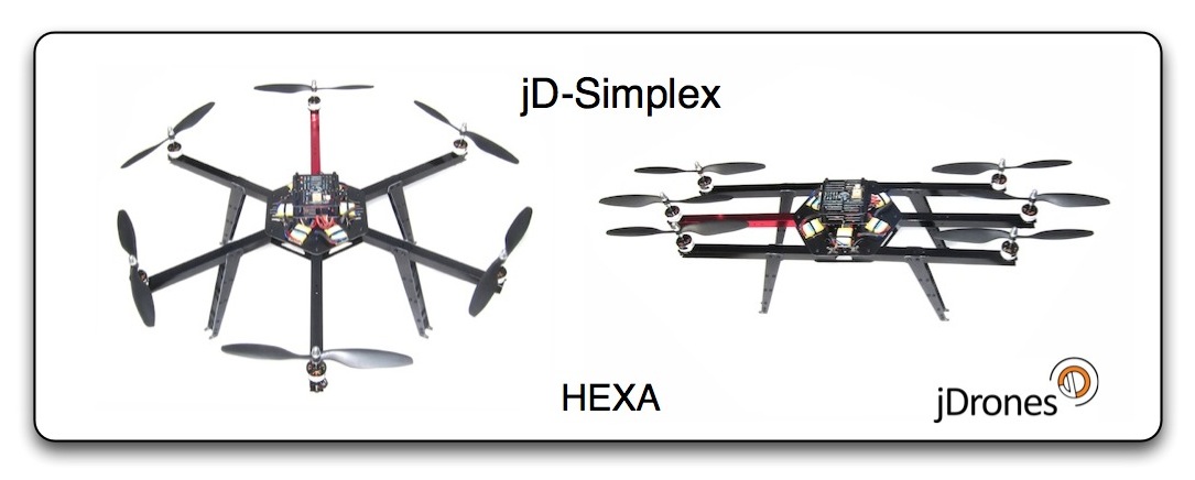
jDrones: jD-Simplex frame series are available now
Another line of ArduCopter frames from jDrones is now available.Frames uses many of the parts that are already widely used on current ArduCopter frames.
All frames are fully foldable for easy transportation. Currently there are Quad and Hexa frames ready and more is coming shortly.
You can fold frames open and arms will lock to their open position and secure them with easy to use lock nuts.
Frames can be directly used with following flight controllers: APM 1.4, APM2, APM2.5, KK-MultiCopter, MultiWii and AutoQuad.
While new revisions are coming, we will keep parts for old revision in stock. Shipping has already started.
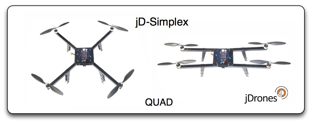
jD-Simplex Quad Rev.A, Empty Frame KIT 68.90 USD
jD-Simples Quad Rev.A, No flight controller KIT, 223.90 USD
jD-Simplex Quad Rev.A, With flight controller KIT (APM) 439.90 USD
jD-Simplex Hexa Rev.A, Empty frame KIT 99.90 USD
jD-Simplex Hexa Rev.A, No flight controller KIT 329.90 USD
jD-Simplex Hexa Rev.A, With flight controller KIT (APM) 539.90 USD
The DC Area Drone User Group had a very successful first fly-in yesterday with 8 members attending and a variety of fixed and rotary wing drones. For many of us who have been learning to build and fly mostly from this blog and message boards it was great to have an opportunity to trade tips and experiences in person with other practitioners of the drone arts. We are now at 52 members and are always looking to expand our community. Please check out the group at http://www.meetup.com/DC-Area-Drone-User-Group/ and consider joining if you are in the area.
we're working on two basic systems: flight control and autopilot
As to the system of flight control, we adopted the software from an open source project called MultiWii (http://multiwii.com). We made our IMU by soldering an accelerometer and a gyro, both of which can be cheaply available by tearing apart a Wii remote controller, onto an Arduino chip and used the IMU to build a quadrotor test bed for flight control software.
The above video shows how the flight control software was working on the test bed when we were debugging it.As you can see, we failed at the beginning where the test bed could barely take off. However, finally it was able to take off smoothly.
As to the system of autopilot, for our tracking system, we decided to adopt the algorithm from TLD which's inventive feature is the ability of real-time learning on the locked target so that it can update the latest samples for its detecting and recognizing. The following video shows its performance in tracking

utility DigitalRadio configure chanel to range1000-2000 ms. /*s1 - s5 & LEDS connected to analog pins 1-5its numbers from 14 to 18 */ #define AnalogOut 10 // PWM out int SelBtn = 14; // default int BtnLevels[19]; void setup(){ Serial.begin(9600);//5 of 6 modesBtnLevels[14] = 0; // 1 buttonBtnLevels[15] = 84;BtnLevels[16] = 127;BtnLevels[17] = 169;BtnLevels[18] = 255; // 5 button //force pwmTCCR1B = 0x01;delay(100); pinMode(SelBtn, OUTPUT);digitalWrite(SelBtn,0);analogWrite (AnalogOut, BtnLevels[SelBtn]); }void loop(){ScanBtns();delay(10);} void ScanBtns(){for (int i=14; i <= 18; i++) ScanBtn(i);} void ScanBtn(int ScanPin){if (SelBtn != ScanPin) {pinMode(ScanPin, INPUT); if (digitalRead(ScanPin)==0) { SelBtn = ScanPin; unsetOther(ScanPin); while (digitalRead(ScanPin)==0); // hold scaning until relise button pinMode(ScanPin, OUTPUT); digitalWrite(ScanPin,LOW); }}} void unsetOther(int excludePin){for (int i=14; i <= 18; i++) { if (i != excludePin) pinMode(i, INPUT); digitalWrite(i,HIGH); } analogWrite (AnalogOut, BtnLevels[excludePin]);Serial.println(BtnLevels[excludePin]); }TX Hobby King 2.4Ghz 6Ch :   
|
Hi Folks, I've been working on sonar for a few weeks and I made 6 landings yesterday as shown in the Video above.
The detailed specification of the Maxbotix MB1230 is here.
The processing of the Sonar information to do some simple filterering is done here.
The Logo Flight plan is shown here.
Best wishes, Pete

As Chris mentioned a few posts previously, we went to the East Bay Mini Maker Faire. I really enjoyed myself and wrote up a trip report here.
http://eastbay-rc.blogspot.com/2012/10/east-bay-maker-faire-demo.html
Congratulations to OJørgen, who was the 30,000th member of DIY Drones! This is a big milestone for us, so I wanted to celebrate with a prize for the lucky user, a $100 gift certificate at the DIY Drones store. (OJorgen, check your inbox!)
There were at 1.4 million page views this month, tied for our record. It took us 33 days to get this latest 1,000 members--we're averaging about one new member every 45 minutes.
Thanks as always to all the community members who make this growth possible, and especially the moderators who approve membership applications and blog posts and otherwise answer questions and keep things ticking here. We've got about 60 moderators now, but if anyone would like to join this group, please PM me. If you've been here for a while and have been participating, you'll fit in great.
I've been thinking a lot lately about how cool it would be to implement inertial dead reckoning on ArduCopter for a gps-free loiter mode of sorts. I just wanted to get some discussion going from people who have studied this or have tried implementing it, as I know it is difficult.
To begin with, this is a good read about getting position from accelerometer data: http://perso-etis.ensea.fr/~pierandr/cours/M1_SIC/AN3397.pdf
So my thoughts are that we could integrate the acceleration reading from the accel, subtracting out the acceleration due to tilt angle (we can do this since we have a nice filtered angle reference, or gyro integration). This, once filtered nicely, should give us a pretty good reading of lateral velocity. Once that was accomplished, we do one more integration, and obtain lateral position. Since all we really need for position hold is a relative position, we could experiement with resetting the position integration at some time interval (or every time the sticks are released) to keep our drift error down. How cool would this be if it actually worked?!!
I am thinking to buy an ArduIMU v3 just to play around with this to see if I can get a robust measurement.
Please chime in on this! If this worked even remotely well, there may no longer be a need for optical flow, or even sonar (as we could get relative Z position too)!
-Jamie
Introducing the Issue and the solution:
We've talked about FRSky's CPPM signal on this other post that compares it with a standard PPM signal. The issue is that originally FRSky's CPPM runs at 18 milliseconds. That short period has no space enough for 8 channels plus a proper sync pulse.
After carrying that issue to FRSKY, Jani came up with two FRSky's beta firmwares running CPPM at a 27 milliseconds period. We did test it at the DIYDrones Dev Team and it seems to work pretty fine.
Some guys at that old post were expressing their worries about the 37Hz update speed from the new custom firmware. However, keep in mind that probably you will not see any difference. Mainly if you aren't a crazily fast acrobatic pilot. Furthermore, our focus here is on drones. A good example is the Mission Planner that uses only 20Hz for joystick control.
Well, now those beta firmwares became official: There are custom firmwares for the receivers D8R-XP and D4R-II on their BetaTestSection. The links are now on FRSKY's download area. (Thanks Vladmir for the heads up).
About the Updating process:
Inside of each update zip file there is a PDF explaining how to update your receiver. I'll not describe it here because it's pointless.
Reading their manual you'll see that an FRSky USB cable is necessary. That adapter is a TTL level "USB to RS232" one.
But what's the difference from that adapter and a common "USB to Serial TTL" one? There is just a single difference: the signal is inverted. FRSky's adapter uses the RS232 logic but not an usual RS232 high voltage level that would vary from -25V to +25V. Though the receiver's serial input has internally not just an inverter but also has a RS232-to-TTL voltage level shifter as shown on the diagram bellow (from FRSky's Two Way System Manual):
How to use an FTDI cable:
When I received the first beta firmware some improvisation was needed because I had no the required FRSky's adapter.
I've used my FTDI 3.3V cable with a little trick and it did work perfectly! All I did was configuring the cable to work with inverted input and output signals. ;)
Here goes how you can make that too (at your own risk):
First you need this powerful tool who did the magic: The "FT_PROG" from FTDI Utilities. It runs from a folder and doesn't need to be installed.
The first thing you'll gonna do is attach your FTDI cable and select "Scan and Parse" from "Devices" menu.
After finding the adapter the screen will be like this:
Now you'll navigate at the "Device Tree" selecting the "Hardware Specific" node for checking the proper options that will invert TXD and RXD (output and input of FTDI cable).
Now click on the "flash icon" as shown below:
On the programming screen click on the button "Program" and watch the status bar until it finish.
That's it! After the steps above you have a TTL inverted FTDI cable.
It's reversible, of course. You just need to follow the same steps but this time deselecting the inverting check-boxes.
You'll just need to use some jumper cables. The receiver can be powered by the 5V output from the FTDI cable.
Remember of crossing the connection between your FTDI cable and the receiver input:
FTDI_TXD (orange) goes on the Receiver_RXD.
FTDI_RXD (yellow) goes on the Receiver_TXD.
If you'll flash your receiver... good look! =)
Please, add comments telling us about your experience on it.
Good news!
The beauty of this community is on the collaboration. This new firmware proves it.
I have the pleasure of announcing that "ArduCAM OSD" and "MinimOSD-Extra" teams are now working together to make MinimOSD better and better.
I've been planning this fusion with Gábor Zóltan and Pedro Santos and we've started a nice friendship.
We spend the latest days merging and retouching everything to improve your experience with the new firmware. The Wiki was also updated for matching the new resources.
What's up?
You'll se all those awesome improvements from MinimOSD-Extra as well as improvements we made together.
The latest one is the new auto detection and updating of the EEPROM mapping .
From now on both OSD Firmware and ArduCAM OSD Config Tool will share the same internal signature.
So, both will detect the need for an EEPROM remapping preventing from loading or saving truncated data.
After a firmware upgrading the OSD Config Tool will detect an outdated mapping updating it automatically.
If you update your firmware by other way, the new firmware will alert you on screen and the Config Tool will repair automatically before you load anything from the EEPROM.
Update your MinimOSD right now. The most important: Have fun!
Important NOTES:
Download it from here:
If you're in the Bay Area and looking for a great place to take the kids this week, the East Bay Mini Maker Faire is a delight. For the second year in a row, we're going to be doing a drones presentation at 11:00am, and Mark Harrison will be doing ArduCopter demos at the front grass area of the school afterwards. Details here.
NodeCopter.js was a full day event where 60 developers got together into 20 teams of 3.
Each team received one Parrot AR Drone 2.0 and spend the day programming (JavaScript) and playing with it. At the end of the day, each team got to present their work to the other attendees.
As we (well, most of us probably) already know the AR Drone is an affordable, yet surprisingly capable quadcopter. The drone itself runs a proprietary firmware that can be controlled via WiFi using the official FreeFlight mobile app (available for iOS and Android).
Unlike the firmware, the client protocol is open, and Parrot publishes an SDK (signup required to download) including a good amount of documentation and C code. Their target audience seems to be mobile developers who can use this SDK to create games and other apps for people to have more fun with their drones.
However, the protocol can also be used to receive video and sensor data, enabling developers to write autonomous programs for the upcoming robot revolution.
This module is still under heavy development, so please don't be suprised if you find some functionality missing or undocumented.
However, the documented parts are tested and should work well for most parts.
For more information, I suggest you to go to http://nodecopter.com/ as a starting point.
Short video of my Tricopter with APM2.5 setup for FPV.


