Atlas is getting a lot smarter. He doesn't fly, yet this is still impressive.
All Posts (14049)
Sort by
We've just returned from a very exciting 4 day tradeshow at the Photo&Film Expo up in Johannesburg, South Africa, the largest Photographic and film show in Africa. SteadiDrone booked a stand and we had our whole range of aerial photo and filming drones there and over the 4 days chatted and shared with thousands of people.
SteadiDrone has been using ArduCopter since the very beginning on all our rigs and ultra big heavy lift octos (Red Epic drones) and have loved the system, it's features, reliability and this forum of developers and people.
Here are a few images from the show, and many more on our SteadiDrone Facebook page (go like it! https://www.facebook.com/SteadiDrone)
https://www.facebook.com/media/set/?set=a.365910503492109.87007.234711133278714&type=3http://
Thanks again to all the devs here that make this amazing flight controller possible. For any tips, advice and tech support on bigger octos using APM, please get in touch.
Regards
Duran + SteadiDrone team
Hi All,
I have been thinking about the way we have implemented our throttle and the performance issues that we have observed. First of all I would like to say that I get great altitude hold. I can cruise around at 1 or 2 meters above the ground with no problems. It is only when I start to get aggressive with my pitch, roll and speed that I start to see areas that we could improve. So I started thinking about how we are doing things and why this might cause us problems.
So the problems I see are:
- The pwm input to the esc is not linear with respect to the lifting force generated by the motors. Randy improved this by adding a throttle curve, however this can only be truly accurate for a particular combination of esc, motor, and propeller AT HOVER. When we start to climb, descend or move forward, the curve changes and we are back to a non linear response.
- Boost throttle compensates for the angle that the copter is compared to the ground. But how much do we compensate? We don’t know because of point 1. We know what force we need but not how this translates to pwm. Hang on...... Force.... Acceleration.....
So I got thinking about how we could ensure we could get the correct acceleration from the props for any given situation. Then I thought we have a sensor to measure that!!! Why don’t we put the Z accelerometer in a pid loop to directly measure and calibrate the lifting force supplied by the motors and propellers. The Pid loop design I started thinking about is shown above and compared to our current design at the top of the figure.
This has a number of advantages over the current system:
- The last pid loop, running at 100 Hz, takes an acceleration request then uses the z-axis accelerometer to vary the motor pwm until the required acceleration is achieved.
- The last pid loop linearises the rest of the system making analysis and tuning simpler.
- The frame translation takes care of the angle boost function automatically.
- When at hover or in fast forward flight changes in pitch will cause much smaller variations in altitude because the last pid loop will be working to ensure the vertical acceleration (in the earth frame) will stay as close to 9.9g as possible. We no longer are waiting to detect a change in altitude, we are reacting when we feel that we are accelerating at the very beginning of the unwanted movement.
- This should also improve the rise on yaw problem. As the yaw command is entered we experience a positive acceleration body frame z axis. The final control loop should sense this very quickly and reduce the throttle to bring it back to 9.8G.
There are a number of problems we may also need to solve:
- The z accelerometer will have noise that may need to be filtered. A moving average filter is the best choice for this because it give the greatest noise reduction with the fastest step response. This filter will be one of the biggest contributors to the delay in the throttle control.
- When at rest on the ground the copter will experience an acceleration in the vertical direction of 9.8G provided the motors are going slower than that required to lift off. How do we ensure that the copter provides the user with the appropriate feedback to let them know that they are near hover or not? How does the user know when the copter is about to lift off? This could be a problem because the integrator could wind the motors down to minimum throttle. This may not increase until the requested G increases above 9.8 and then it could increase very quickly to make the copter take off as requested. I believe that these effects could be minimized by sensible selection of Imax in the final loop but only experience will say.
Ok, so that pretty much sums up my idea. I would really appreciate any feedback that people can give. Has this been tried before? Does anybody know if this is being done in other systems?
Thanks for taking the time to read this far,
Leonard

Da Vinci sketched the oldest known plans for a human-powered aircraft in 1485. Yet it wasn’t until 1977 that the first one truly flew. Flight requires lift, when the net air pressure pushing upward counteracts the craft’s weight. For years, many assumed that flight required more lift and more power than the human body alone could provide (although the admonitions did little to stop myriad failed attempts). But inventors persisted. Aircraft fly using three basic configurations: fixed wing, flapping wing, and rotors. In the last 50 years, inventors have conquered fixed-wing and flapping flight. Now they are on the verge of overcoming the greatest challenge yet: vertical takeoff.


Click here to see a history of flight in the page of PopSci
To fly a human-powered helicopter, a pilot would likely have to produce 500 watts of power. Even the fittest pilot could not sustain that output, says Antonio Filippone, an aeronautical engineer at the University of Manchester in England who has published two papers analyzing theoretical human-powered helicopters. “You can lift off,” he says, “But for more than a few seconds, it is not possible.” We’ve heard that sort of thing before.

AIRPLANE
Fixed-wing flight
The Challenge: Fixed-wing flight requires an efficient airfoil, such as a wing that’s curved on top and flat on the bottom. As the airfoil moves forward, air streams faster over its top than underneath it, creating a difference in pressure. When the pressure below the craft overcomes the pressure above it, there is a net upward force. Most planes use engines to get enough forward motion, but people can’t propel a vehicle nearly as fast. The Solution: In general, the longer the wings, the more lift. In the early ’60s, Southampton University undergraduates built a 130-pound craft with an 80-foot-wingspan and a bicycle-style transmission connected to a propeller. It flew a third of a mile but had significant steering problems. In 1977, engineer Paul MacCready designed the Gossamer Condor, a 70-pound aluminum and plastic craft with a canard—an airfoil on a boom in front of the fuselage. It was more maneuverable than its predecessors and flew in a figure eight around markers a half-mile apart, winning the Royal Aeronautical Society’s prize for the first controlled and sustained human-powered flight. There’s still room for improvement. For example, engineers have refurbished the ’90s Airglow (seen here) with bent wingtips and curvier wings—improvements that stabilize it during turns.

ORNITHOPTER
Flapping-wing flight
The Challenge: Small animals such as hummingbirds beat their wings fast enough to stay aloft entirely from flapping, pushing more air down than they do up and creating a net upward pressure. But at large scales, it’s difficult to beat quickly enough to remain in the air. Bigger flappers, therefore, require a boost from forward thrust. Think of an engine pushing forward a flapping-wing plane, or ornithopter. The Solution: Larger birds’ wings flap, but they also twist forward and back as if jiggling a doorknob, which generates extra forward thrust. So as a graduate student at the University of Toronto, aeronautical engineer Todd Reichert and fellow students designed their craft, named Snowbird, with wings that both flap up and down and twist 10 degrees. They used computer simulations to fine-tune their design. And they gave Snowbird a wide, 105-foot wingspan and employed carbon fiber and Kevlar to keep it light. A person generates power in the 94-pound craft using a leg press similar to those found in gyms.
On August 2, 2010, on a field in Ontario, a car towed the craft forward until it glided into the air. Then the car stopped towing. As Reichert worked the leg press, the Snowbirdflapped its wings and flew on its own at a height of 11 feet for 19.3 seconds, traveling 475 feet.

HELICOPTER
Rotor-based flight
The Challenge: A helicopter flies when its spinning rotors force air down, which decreases air pressure above the craft and increases it below. Unlike planes and ornithopters, helicopters cannot rely on forward motion, making flight much more challenging. Helicopters also generate turbulence that can cause serious stability problems. Several teams are trying to prove that they can conquer vertical flight by winning the American Helicopter Society’s Sikorsky prize, a standing $250,000 award for a human-powered helicopter that hovers for one minute and hits a minimum altitude of three meters (9.8 feet), while staying within a 10-meter (33-foot) square. The Contenders: The University of Maryland team’s Gamera II helicopter is a quadcopter, a craft with four 42.6-foot-wide rotors connected to a bicycle-like transmission. Several smaller rotors near the ground can lift off more easily than a single large one. They also balance one another for better stability. In June, a pilot sat and pedaled with his hands and feet to raise the Gamera IIabout one foot off the ground for 49.9 seconds.

Aeronautical engineer Neal Saiki, who designed the first human-powered helicopter to lift off in 1989, is back with a new craft: the Upturn. A pilot pedals to spin its single, 85-foot-wide rotor with four blades, two of which have propellers at their ends, which help with stability. Each blade also has an adjustable flap and a sensor to detect vibration and balance, and Saiki’s software tweaks the flaps’ angles in real time to compensate for wobbles. In June, a pilot lifted the Upturn two feet for about 10 seconds.
The competition is still heating up. Snowbird co-designer Todd Reichert officially registered for the helicopter prize this July with a new group, but it hasn’t yet released a full design of its quadcopter. Maryland continues to improve its craft. Saiki aims to use a stronger pilot. And team gravity will be fighting all of them every step of the way.
http://www.popsci.com/technology/article/2012-08/they-said-it-couldnt-be-done
From the great IEEE Spectrum Automaton blog:
We’re used to thinking of robot swarms as consisting of lots and lots of similar robots working together. What we’re starting to see now, though, are swarms of heterogeneous robots, where you get different robots combining their powers to make each other more efficient and more capable. One of the first projects to really make this work was Swarmanoid, with teams of footbots and handbots and eyebots, and researchers presented a similar idea at IROS earlier this month, using an AR Drone to help a swarm of self-assembling ground robots to climb over a hill.
The focus of this research is communication: getting a flying robot to be able to communicate with a swarm of ground robots by relying exclusively on visual feedback from LEDs. All you need to get this to work are lights, cameras, and some mildly intelligent robots: you can leave your maps, GPS, IMU, hardware IDs, and all that stuff at home. Here's a video of the system in action:
As interesting as the communication is, it's the applications that really make this video worth watching. Since the ground robots can't see very far, they rely on the quadrotor to scout ahead and estimate the parameters of upcoming obstacles. Then, the quadrotor instructs the swarm on the ground how to team up to best overcome those obstacles. With the hill, for example, the quadrotor can use stereo imagery to compute how steep it is, run an onboard simulation to see how many ground robots will have to team up to make it over, and then give instruction and direction to the robots below. Very clever.
"Spatially Targeted Communication and Self-Assembly," by Nithin Mathews, Anders Lyhne Christensen, Rehan O’Grady, and Marco Dorigo, from Universite Libre de Bruxelles and Instituto Universitario de Lisboa, was presented at IROS 2012 in Vilamoura, Portugal.

Update 10/22/2012 - For those few who may be interested, I'm now using this software on my personal quad with ACM 2.7.3 and 2.8. This software now compiles with Arduino 1.0.1 and works with Mavlink 1.0 or 0.9. The wiring and hardware requirements has not changed. You can download the software from my personal website at this link.
Original Post:
Since I purchased my Arducopter last November, I've wanted to use my NTSC video camera, Remzibi OSD, and 1.280 Ghz video transmitter with my quad and experimented with different ways to do it. It was easier with Arucopter NG RC2 since Mavlink was not in use and I could generate my own serial stream to the OSD. With the release of Arducopter 2.0.x and Mavlink it was a little harder. I really wanted to have Mavlink up and running to my Ardustation tilt/pan antenna and notebook while using the on board OSD.
My solution was to add an Arduino Pro mini to my quad configuration and modify some Mavlink Ardustation software from phillip.anthony.smith to create the serial stream that the Remzibi OSD likes. The details of this mod and link to the my Mavlink to Remzi converter software is available here:
As mentioned in my earlier Arduino DUE post (DUE is now released, BTW!), the new Arduino IDE will make it easier to support different hardware platforms, including the PX4 board. Now the beta of Arduino 1.5 is out, and the team explains more:
The new Arduino 1.5 software brings a number of improvements, some in support of the new Arduino Due board and others to make it easier to install libraries and to simplify the boards menu. While these new features should work well, we expect to get lots of feedback and to iterate on them in future releases of the Arduino software. That also applies to the new (experimental) libraries for the Due, which add features like USB Host, audio playback, and cooperative scheduling. In the short-term, if you’re not using the Due, you might want to stick with the current 1.0.x (AVR-only) releases of the Arduino software; Arduino 1.0.2 will be out shortly. In the long-term, though, we’re going to be basing the Arduino software on the Arduino 1.5 code. Here’s an overview of the improvements and changes it contains.
Support for Multiple Microcontroller Architectures and Toolchains
While the interface for compiling and uploading sketches remains the same, we’ve made some significant changes under the hood in order to support the new 32-bit, Atmel SAM3X ARM processor on the Due. The new Arduino environment (IDE) can now be configured to target multiple processor architectures, each with its own toolchain and compilation process. To support a new processor family, the core language and libraries need to be ported (as we’ve done for the Due) and some configuration files edited to specify the commands for compilation and uploading. We’ve focused on ensuring that this new system works seamlessly for the Due and our existing AVR-based boards, but with some tweaks and improvements, we imagine that it will allow the Arduino environment to work with many, many more microcontrollers. We’ll be posting more details of this new system soon but, for now, you can look at the “avr” and “sam” directories in the Arduino software for an idea of how it works.
Note: the changes to the underlying configuration files means that older “third-party hardware” folders will require some tweaking to work with Arduino 1.5. We’ll try to improve backwards compatibility in future versions of the software but, for now, you’ll need to work with makers of third-party hardware to update their files for Arduino 1.5.
Easier Library Installation
Arduino 1.5 makes it easier to install libraries. We’ve added a new “Add Library…” menu item (inside of “Sketch > Import Library…”) that prompts you select a library zip file or folder on your computer. It then copies it to your sketchbook folder and adds it to the list of installed libraries. You can still install libraries manually but this is a simpler alternative.
Simplified Boards Menu
With the addition of the Due, the boards menu in the Arduino software was getting so long that we decided to simplify it. To do so, we’ve separated the choice of the board itself from that of the processor (microcontroller) on it. For example, if you’re using an Arduino Mega with an ATmega1280, select “Arduino Mega” from the boards menu and “ATmega1280″ from the processor menu. To make things easier, the processor menu defaults to the microcontroller on the most recent version of the selected board. So if you have an Arduino Mega with an ATmega2560, you can simply select “Arduino Mega” from the boards menu and the processor menu will default to the appropriate item (“2560 or ADK”). If the selected board only has one processor option, the processor menu will be disabled. (For example, every Leonardo board comes with an ATmega32U4.) We hope this makes it a little easier to find and select the board you’re using.
From the blog at Nebraska's Drone Journalism Lab:
"Nebraska is seeing a drought worse than the Dust Bowl drought of the Great Depression. The least amount of rain fell on the state this summer since records were kept in 1895. From the ground, dead lawns and distressed trees show the drought up close. But the view from an Unmanned Aerial Vehicle nearly 400 feet off the ground provides a perspective on just how wide spread the drought’s impacts really are."
Matt Waite, who has an account on DIYD, and his students at the Drone Journalism Lab have been working hard all semester, and this is a great first example of a journalism investigation using drones. They also back up their reporting with climate data, which adds some excellent context.
I'm not sure what the longevity of brushless motors in water would be - you wouldn't want to get water in the bearings. Seems like a pretty cool frame nonetheless.
Great work from my friend Andrew Plumb. From the Ponoko blog:
Andrew Plumb (aka @clothbot), who I’ve interviewed here before, published an awesome glider design today called the PaperFly.
Based on an earlier glider (the Bukobot Fly) that was entirely 3D printed, the PaperFly is instead a minimal frame printed directly onto a sheet of tissue paper!
Andrew also put a tutorial on Instructables that covers the prep work necessary to make one of the gliders. Basically, in order to keep the paper flat and unmoving, it has to be secured in a cardboard frame that is then placed on the printer’s build platform. Like this:
Once the glider has finished printing, the weight of the nose must be adjusted to make it flightworthy. How is that done? By adding LEGO pieces to the connectors on the nose cone, of course.
The design file is an OpenSCAD script, so it can be extensively customized or adjusted to fit on the user’s own 3D printer.
If you’d like to make one for yourself, check out the full details on Instructables here:http://www.instructables.com/id/3D-Printing-PLA-on-Tissue-Paper/


hey guys,
just thought I would show of one of my latest efforts.A servo hacked continuous, controlled by a maple reading a 12 bit absolute encoder controlled to move to any absolute position.
the encoder is a AS5045 read by a maple dev board. working on an open source continuous rotation gimbal to go with the techpod, avalable for pre-order @ http://hobbyuav.com/
After numerous bench tests, re calibrations, and more bench tests I was finally brave enough to take my 3DR quad out for it's first flight -albeit tethered. I did some initial outdoor ground testing in which I brought the throttle up to the point of takeoff but noticed that the quad was showing a tendency of tilting forward and right so I killed the throttle, ran this test several times, and decided I didn't want to attempt the takeoff having no clue what might happen. So...
I threw together a quick test rig on nearby deserted swingset to evaluate what the quad would do when in the air. The video clip below shows the outcome... Without any stick input the quad wants to fly forward and to the right. I was able to counter it with stick movement and fly the quad around the rig without too much trouble but if I stopped countering the roll/pitch it would try and wander (this is evident in the video when you see it start to move sharply to one side).
I've ruled out motor rotation, wiring, and prop direction via another round of tests to verify everything's good. That leaves me suspect of:
- mis-calibrated radio
- mission planner radio calibration
- Radio Trims?
- Leveling (although I leveled before this flight)
- Auto-Trim (I've done none of this yet)
I also found the following in a FAQ post:
"My copter yaws right or left 15° when I take off: Your Motors are not straight or your ESCs are not calibrated. Twist the motors until they are straight. Run the ESC calibration routine."
I've calibrated the ESC's many times over the learning process how often should I need to re calibrate them? As for motors not being straight... I've checked that they're secured properly to the frame, not sure what could be off.
UPDATE:
I originally posted this in the Forums and got some great advice but I thought I would consolidate and put all my experiences on a blog.
The solution for me was a simple radio re-calibration on the TX(er9x) and then a re-calibration of the radio in Mission Planner. Finally ready for some flight!
What do you do once you have two NanoQ's flying? Dogfighting!
NanoQ Quadcopter Dogfight from QFO Labs on Vimeo.
These are the NanoQ copters flown with the Mimix Controller from QFO Labs.
Check out more videos and project details at KickstartMimix.com
Hackaday reports:
After a years-long wait, an ARM powered Arduino is finally due. The Arduino Due will finally be released this coming Monday.
On board the Arduino Due is an Atmel-sourced ARM Cortex M3 microcontroller running at 84 MHz. The Due has an impressive list of features including a USB 2.0 host, compatibility with the Android ADK (lest you still need an IOIO), 12 analog inputs with 12-bit resolution, 2 analog outputs running at 12 bits, a CAN interface, and more input pins than you can shake a stick at.
For a full list of features, you can grab this PDF we picked up when we saw the Due at Maker Faire NYC
This hardware update to the Arduino platform makes a lot of very cool builds very possible for even the beginner hardware hacker. Of course the Due will be used for controlling drones and UAVs, laser cutters and 3D printers, and playing WAV files from the analog outputs. The much improved hardware opens up a lot of other possible builds including making your own guitar pedals – DSP is a wonderful thing – and reading the telemetry from your car in real-time via the CAN bus.
Although it’s not available right now, you will be able to buy an Arduino Due for $49 USD this coming Monday at your favorite electronics retailers.
The ArduCopter/ArduPlane team is currently focused on porting the code to our PX4 board, which is based on a much faster and more capable ARM chip than the DUE and has other cool stuff like a RTOS already up and running. But one of the cool things about the Arduino DUE release is that includes some improvements to the Arduino IDE to support a wider range of hardware. So our near-term priority will be to see if the Arduino IDE can be modified to support PX4, which will allow us to retain the accessibility of Arduino without having to support two different ARM-based hardware platforms.
Sometimes I need some info regarding APM2 and iI have to search in different internet pages and forums for help, so i start to collect info, pictures and some tips all in one word file. I believe that this might help because now we have all in one .pdf file. I hope that none of the pictures are copyright but if some one don´t want to have their pictures in this "manual" please tell me and I will remove them.
Some FPV from the summer. Testing out OP CC3D on a QAV500.
...something beautiful is born.
Just this week, after a suggestion from one of the Kickstarter backers, we are now collaborating with Quantum Robotics, pairing our R10 Advanced Quadrotor system with the Quantum Robotics Q2 XBee Handheld Controller, a programmable, customizable and hackable XBee controller that you may have seen before
There's more details here: http://www.kickstarter.com/projects/1101297082/r10-quadrotor-powerful-inexpensive-and-customizabl/posts/330859
The R10 Advanced has a GPS/XBee module that handles autopilot and telemetry, which can be used as an alternative to a regular RC transmitter (or used in conjunction with a regular transmitter to send telemetry to a laptop)
But we realized that it also makes it completely compatible with the Quantum Robotics XBee Handhel Controllers (we'll ensure that they're fitted with the correct XBee units), which would be able to send the R10 manual control information, either using MAVLink version 3's MAVLINK_MSG_ID_MANUAL_CONTROL, which is what the R10 is set up with currently, or by some other protocol. We'll be working closely with Quantum Robotics to see if they'll support the latest version of MAVLink on their controller so that it can be used with other craft. We also want to use the display for battery levels.
The extra potentiometers on the transmitter would be excellent for fine-trimming controls, tuning the craft's flight dynamics or sensitivities on the fly, or controlling extra servos, like altering the default position of a stabilized camera gimbal! So this is definitely a very exciting opportunity for us, and we will be exploring the full possibilities soon.
The VERY interesting thing is that with all the extra buttons and switches on the controller, along with the mesh network/broadcast capabilities of the XBee, there'll be a possibility in the future of controlling a fleet of craft from a single Quantum Robotics Q2 XBee Handheld Controller using the buttons/switches to toggle control between individual quadrotors (the other quadrotors would have to be put into GPS hold). Could potentially allow a single person (presumably with super-human multi-tasking capabilities) to control a load of quadrotors to film an event from all different angles.
...Or it could be a recipe for disaster.
This is something we're keen to test out, but we'll keep that for later.
We've added a pledge level on our Kickstarter that would let people grab an R10 Advanced with a Q2 XBee Controller (we'll be fitting the controller with an XBee ZB Pro needed for compatibility).
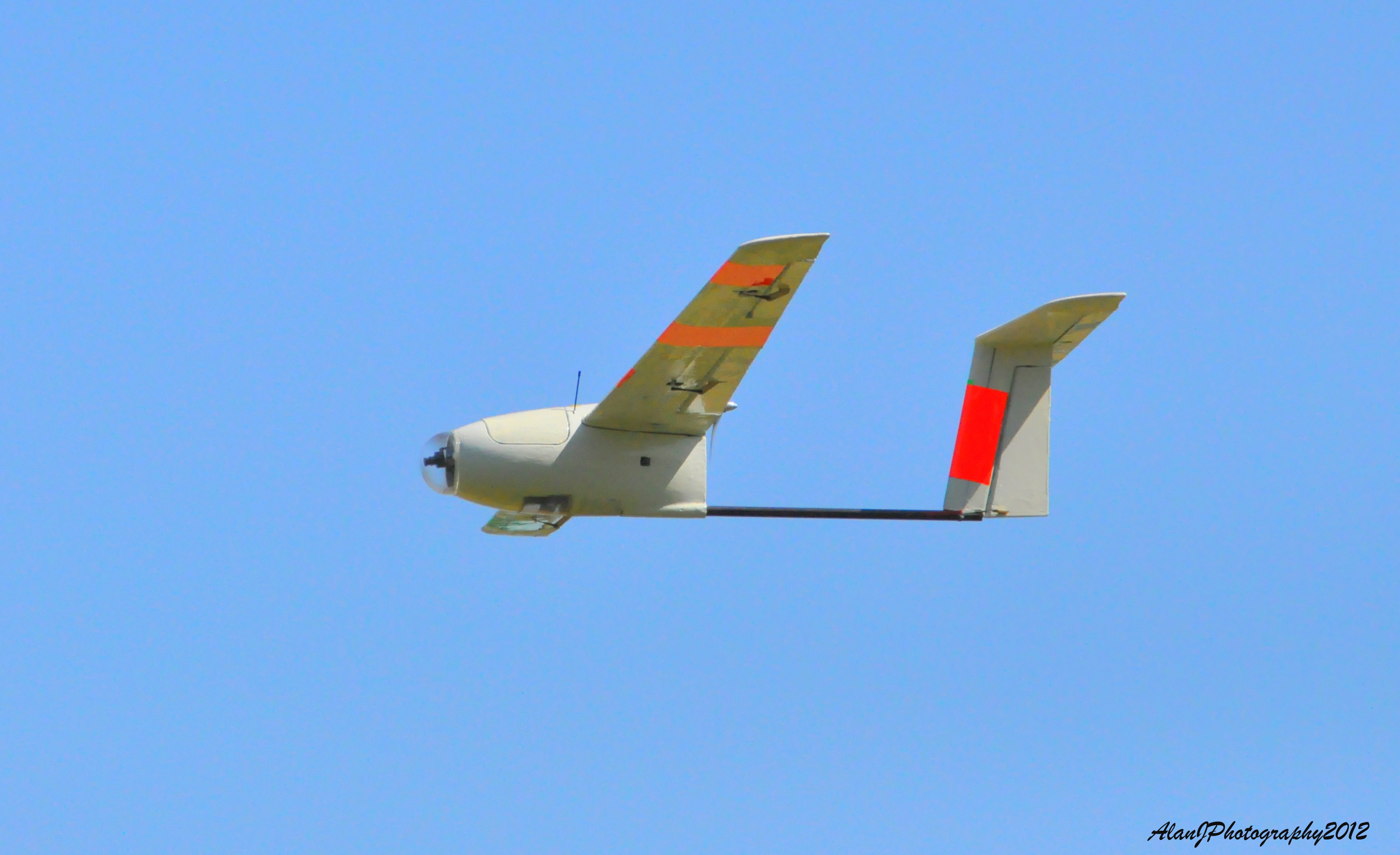
Team Echelon- Flying the X-8 wing, Skywalker, Penguin and more!
This is a bit of an odd one, but for $2,000(!), this rover that can also fly as a quadcopter can be yours. Or you can back the project at a lower level and get the design files when he's done.