All Posts (14056)
Sort by
You all have heard and seen the commercial for Tempurpedic mattress
where the girl jumps on one end and the glass of wine on the other end
that doesn't spill ?
Look them up on the internet and request a free sample. Perfect size and
it REALLY kills the vibration, especially on ArduCopter.
Put this stuff in the Professional housing box under and around the mega and you will be all set.
Earl
Hi,
Some people asked for a few more details on the mouse sensor position hold I am experimenting with on my quad (originial post here), so here we go:As I mentioned in the original post, the sensor is an ADNS 2610 made by Avago. This is a fairly ubiquitous sensors found in many cheap mice - the reason I chose this one is two-fold: there is good documentation available for it (e.g. the datasheet, or just google for it, there are plenty of people who hacked it), and it provides a mode in which the 'raw' 18x18 pixel image can be read out of it, significantly simplifying the setup of appropriate optics.
I ended up not finding a mouse with that particular sensor, so I ordered the raw sensor on Digikey instead. According to the datasheet, 3 caps and 1 oscillator are required in a minimal circuit - all of these are cheaply available at digikey.
Above is an image of my prototype circuit: on the right you see a lens with a screw-type lens barrel from a cheap (around $10 at Walmart, I think) keychain camera, in the center you can see a raw ADNS 2610 and on the right is the circuit itself. The lens I ended up using is not this exact one, but one from a different camera which looks very similar - either one would have worked.
I use the altitude data from the sonar range finder together with tilt information from the IMU to get an absolute position reference.
Hope this was interesting,
Marko
Professional housing for professional electronics
I have made this evening on my CNC laser for a housing
the mega !
It is based on Arduino Mini. Quite a difference from most other copters that use dedicated sensors and super-powerful boards.
Tricopter 06 - TriWii NK test 1 from Joël Cordier on Vimeo.
Another interesting thing from this project is the frame. It looks all carbon fiber, very nice.

Also look at this video showing how to tune the PID constants on the field, directly from the radio: this guy is a genius
Tricopter 05 - TriWii led & buzzer demo from Joël Cordier on Vimeo.
O'Reilly Radar has a cool report on a speech at Maker Faire last week by White House Office of Science and Technology official Thomas Kalil.
Key sentence: "We are seeing the early beginnings of a powerful Maker innovation ecosystem. New products and services will allow individuals to not only Design it Yourself, but Make it Yourself and Sell it Yourself."
He highlighted DIY Drones as a good example of that: "For example, one community called DIYDrones has developed a $500 unmanned aerial vehicle using open source chip sets and gyroscopes."
The full speech is here.
(picture from Kalil's talk earlier this year at AUVSI)


From Robot Dreams:
"The Shrediquette DLXm is an amazingly clean and efficent tricopter design weighing a scant 628 grams yet capable of carrying a payload of up to 550 grams in
sustained flights lasting as long as 18 minutes. It has a lift to weight
ratio of 2.87:1 and incorporates features that make it an absolute
pleasure to operate and experience (at least from the video since we
haven't had the opportunity to fly it in person, yet…).
The tricopter designer, W. Thielicke, is a PhD student and research assistant at the University of Applied Sciences, Bremen, Germany. He's generously posted the latest versions of
the project publically on his blog including the instructions and
manual, source code, PCB layout (Eagle format), configuration tool
(GUI), and PC -> PWM converters."
After more than a 1,000 commits and many thousand lines of code, the public beta of the ArduPilotMega code is now out. You can get it here. Note that the new libraries requires a slightly different installation process, so read the manual so you can put the libraries in the right folder. The code won't compile if you don't. Also, you'll need to be using Arduino 19 or higher.
New features include:
- An awesome command-line interpreter (CLI) running on APM, which allows you to make most common configurations and setup without having to recompile the code.
- The CLI also allows you to interactively test all your hardware components--no messing with Arduino code or configuration files if you don't want to!
- Powerful new scripting commands and flight options.
- New FastSerial code, replacing the standard Arduino serial code, which makes serial communications lightning fast.
- The entire code has been re-architected to use libraries, which are shared across the ArduPilot projects. That way we can improve everything from GPS parsers to basic DCM routines and all the projects will immediately inherit the improvements. That not only means better code for everyone, but much easier maintenance for the team.
Speaking of the team, special thanks to the core APM dev team that put in so much work and creativity to get us here. These guys have worked tirelessly on this, with daily coding sessions and weekly dev conference calls, all year. This is a huge project, perhaps the most complex Arduino code ever written, and these are the stars who led it:
- Jason Short
- Michael Smith
- Doug Weibel
With help from some ArduCopter team members:
- Jose Julio
- Jani Hirvinen
Config utility wizadry from:
- Michael Oborne
- Ted Carancho (ArduCopter Configurator)
As always, please report all bugs and problems in the Issue Tracker. The developers can't respond to bug reports in blog comments and discussion forums.
From a Guardian report:
"Two official safety inquiries took place into the military use of drones over southern England after near-collisions with helicopters, the Guardian can reveal.
The investigations are the first of their kind involving unmanned aerial vehicles (UAVs), which are increasingly being flown in British civilian airspace after extensive use in Iraq and Afghanistan.
The inquiries by Airprox, the body that investigates reports of near-collisions, relate to flights on 12 February by a Desert Hawk 3 (DH3) drone owned and used by the army. The drone was being flown in military airspace over Salisbury Plain and operated from the ground.
In each case Airprox concluded that action taken by the operator on the ground prevented collision with the helicopter. "
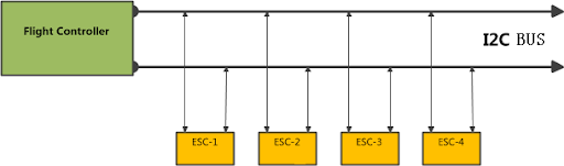
four-rotor aircraft mostly use I2C digital communication. It put all
brushless motor speed controller connection in series on the bus through
two data lines (one for the clock SCL, one for data SDA), and send the
control signals to brushless motor speed controller at regular time. MK
products used this communication mode, as well as our early X500D X600D.
I2C communication mode looks perfect, you can save the number of
communication cable, moreover does not need to modify the hardware and
interface when extended the four-rotor to six or eight rotor, just
directly attached to the existing communications bus. This is a economy
design that easy to extend.
However, there are some problem in actual use:
1. As long as one of brushless motor speed controller broken down, will affect all the other brushless motor speed controller on I2C bus, this failure is fatal. Although we can change the software to make the all brushless motor speed controller to enter the normal working condition after broken down. But the I2C communication mode has greatly increased the probability of failure, for expensive camera equipment and x650 aircraft, this is clearly not the best choice.
2. ESC is working in Series on the I2C, the more ESC, the more time cost in communication. The maximum communication rate of the standard I2C is 400kbps, for reliability and stability, the general four-rotor will use the communication speed 100kbps, means it can only send and receive data only 10 byte per 1ms. No enough for high-speed and high-precision motor control, as 500Hz and 1000 control level with the increase in the number of motors.
3. There are many ESC in in the field of model airplane before four-rotor aircraft invention, after years of development they are become very mature and reliable and has a very rich type and power output. But I2C are incompatible with these traditional ESC interface, and nothing much in the type, inconvenient to extend.
In order to solve these problems, we used a more stable, reliable interface solution that compatible with current brushless motor speed controller, we called it UltraPWM technology:
All ESC are connect parallel to flight controller, any one of them brokecn down will not affect the work of the entire system, aircraft still able to landed safely via the remaining seven motor. This is essential for multi-rotor aircraft to meet high security requirement.
Motor control frequency 500Hz, 1000 control level. The the control pulse width error between two brushless motor less than 1%.
Compatible with the existing ESC interface, without requiring high speed and high precision control, instead, it can work with the general speed controller too.
Due to most of xaircraft X650 documents are chinese that hard to get the details of it, for convenience I will translate(poor translation) all article on their website and post it in www.xaircraft.org, also this forum.
The new pick-and-place machine at the DIY Drones factory is now in full production, and we're filling boxes like this with the IMU shields in preparation for the ArduCopter commercial launch and APM public beta code (the code will probably go live tonight). Right now we can make about 120 boards a day, and can ramp up to 150/day if needed. Right now we're filling back orders, but it should be back in stock next week.
Look for pricing and pre-order plans for ArduCopter over the next week. This is going to be big!
Time has finally come!! ArduCopter Alpha 1.0 is here
We have been talking about this release for a while while it's been in development and testing, but it's finally ready for daylight. Its been long and exhausting 4 months or so that we have been doing this project, there has been a lot of long nights and will be more. But today is a huge milestone: on behalf our whole team, I'm happy to release our first official ArduCopter Alpha 1.0 release for our users.
This code has been tested over multiple ArduCopters, they all worked out of the box after proper installation eg. EEPROM reset and calibration and we have not found anything alarming but I am sure that there are bugs lurking behind the corner. If you are afraid of bugs, then better to wait till we are in beta but if you think you can handle some small issues this is now ready for ou to play with.
What you need to know of this release are:
- This is an First Alpha release so there might be some bugs waiting, we just haven't found any yet.
- New orientation system: Always mount your APM/IMU aligned by Front/Rear Arms eg. in + configuration. X mode is switched from software it self and you are not allowed to rotate your APM on frame.
- Before switching to X mode, test your settings and Artificial Horizont on + mode. When X mode it activated from software, Artificial Horizon on Configurator shows AH incorrectly (this will be fixed later on Configurator itself)
- On X mode, your original "nose" rotates 45° to CCW eg Front becomes Front/Left
- New variables and default settings so RESET your EEPROM by doing Initial Installation procedures
- Unzip file and copy all Libraries from this zip file to your Arduino/Libraries folder and replace them if you had some of the libraries already installed. This Alpha release is designed to work with Libraries included on ZIP file.
- Zip file contains Arducopter_alpha_RC1 folder where all firmware codes are and also libraries folder is there.
Alpha 1.0 Features:
- Acro / Stable modes, changeable by switch input from radio
- + and x modes, changeable from software code, APM orientation always as +
- Magnetometer support (optional, default is off)
- Finetuned PID controllers on stable mode
- More cleaner code
- 200Hz main loop
Sorry guys, no GPS features yet. We have some issues with it so we temporary took it out. We try to find it out as soon as possible. This is built on the APM code, which has full scripted GPS navigation, so as soon as we turn it on ArduCopter will have full UAV functionality.
For feedback please use #47 ticket on our issue tracker in here.
If you find bug or expect that you have a bug, please open new issue for us so we can look it. But before opening issues, try to reproduce your problem 2-3 times at least. If you can reproduce it, post an issue for it.
Also if you have code proposals of feature proposals you can post them too as new issue. But again before posting, check our wiki pages to see if someone has proposed it already of it or proposed feature is already on issue lists or on our software roadmap.
General help can be found from our Wiki pages at GoogleCodes ArduCopter Wiki
Happy flying guys/gals and don't do anything that I would not do :)
File download: ArduCopter_Alpha.1.0
(Current and future files can be found from wiki download areas too, http://code.google.com/p/arducopter/downloads/)
Long live simple solutions to difficult problems.
Dr Acevedo-Whitehouse told BBC News she was delighted to receive the spoof honour: "I was slightly bemused at first, to be honest, but I think that it is important to recognize (and communicate) that science can be fun. My colleagues and I are actually quite proud to receive this award now. Beyond the actual results (which are actually very interesting) we certainly have had fun doing our whale-snot research!"
Hey Guys! First, I have to confess. I lied... It did not started by looking and drawing on an autocad 2009 computer screen.
It started with some delirium about designing a different kind of quad. I talked about it to my partner and we both agree that variable pitch quad was something to consider. Before many of you start screaming about complexity I would like to give you my position about it.
The venerable 4 motors / 4 ecs quad is the way to go for simplicity, affordability and quick fun.
It is the perfect platform for what it is intended for. Some are dreaming about a quad entering a contest like the outback challenge but we all know that autonomy is not what a quad is made for.
Also, redundancy is null in a traditional quad. Loose one motor and zap it goes. Loose a prop and zap it goes again. Lets pushed it further, what would it be like to have a quad to do 3D flying like a TREX 450 helo? And maybe a very different kind of 3D flying? What would it be like to have a quad flying with the speed and the autonomy of a plane? What would it be like to have that kind of quad doing it with absolute redundancy and also with total safety to surrounding peoples and infrastructure?
That is where you will say I have got crazy. My friend and I have the intention of proving you right about this craziness by proving you wrong about the limitations of a quad.
One last word, this one about KISS (keep it stupid simple). It is my opinion that you can KISS a simple design by design, OR, you can KISS a complex system by a simple design. Both result should be targeting a different mission and be good at it. DIY does not keep one from making it a complex but efficient system. Alright, money can do that so that is why we also added that requirement to our project.
You can now see that we are indeed crazy and some of you probably are to. Those one will understand that a guy can't sleep over some crazy ideas and some times find the solution in the middle of the night. That is what happen to me when at 2 o'clock in the morning I saw 4 penny's standing side by side on the night table. ZLAMM ! Here is the simplest way to have 4 rotors turning by opposite rotation pairs. You all know that it is a requirement for yaw control of a quad. Many have tried to figure it all and it was there, costing only 4 cents.
So now, talking about affordability... What looks just like a quad arm but with a variable pitch head? Many of you again thought about that but a few tried it. You are right, an helo tail boom seems to fit the profile. And what is the most common helo with easily available, affordable parts? The trex / clones family. Just check on eBay, it is crazy what our Chinese friends can do for almost nothing. If you want some quality, you guys from the US are pretty good at it although a little bit expensive. But hey ! you get what you need for the place you need it.
Ok now for my Fans Club, here some more details... Please understand that the next video clip is showing an hand drilled crude prototype never intended to fly. It was merely a proof of concept for a gear train and also maybe a dream catcher. If this is bothering you and your are disappointed, I will stop right here, just let me know...
Got to love that 179$ MSRP for a HD Go Pro though you lose ability for external battery and external screen, but who cares, get this, strap it into a camera mount, maybe with an FPV camera attached for sending back fpv video, as well as for aiming the go pro
walla
:)
The five teams that made it past the qualifying did better than ever this year, but nobody won the $50,000 prize.
Here's a news report of the results. Excerpt:
"No team completed the mission with total success; however, the team from the University of North Dakota came within range of the mannequin, but the UAV failed when it dropped its water bottle payload too early.
The North Dakota team was awarded a $15,000 "encouragement prize" for its efforts in locating the downed mannequin.
Another US team made it into the vicinity of the mannequin, thwarted only by a technical fault that saw the UAV abort its mission and return to base."
From another news report, Team Robota, the winner of the Sparkfun Autonomous Vehicle Competition, came very close, too:
"The Robota team, also from the US, made it into the area in which Joe was located before a communications failure saw their UAV abort its mission - they won $5000."
The first video from Joes position is now out
Our big new Manncorp pick-and-place machine is now up and running in our new San Diego factory, joining the smaller pick-and-place that we already had. In the above video, it's placing components on IMU shields in pairs. We should be back in full production by the end of the week. We have all components on hand, including the hard-to-find dataflash chips, so we should be ready to meet demand for ArduCopter and the public release of the APM code. (ArduCopter pre-orders will probably begin in about two weeks, with shipments in about a month)
details of it, for convenience I will translate(poor translation) all
article on their website and post it in www.xaircraft.org,
also this forum.
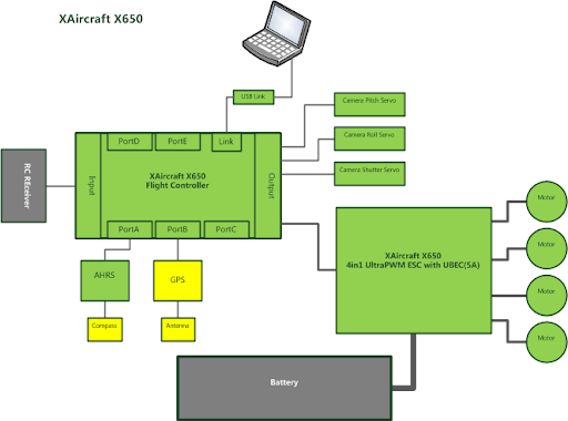
XAircraft Flight Controller Architecture Design
XAircraft has designed several flight controllers for internal research and development and testing without sell
since 2007.
The master control chip ARM of standard flight controller provide 100MPIS processing power to meet the requirements of complex and high-speed control. Flight controllers support 7 exptend modules, two of them are built-in input signal capture module(input module) and control signal output module (output module).
Input Signal Capture Module(Input Module) Features:
Support 12-channel remote control signal capture.
Each capture channel has 1us pulse width identification ability.
Compatible with any type and frequency remote control, such as Futaba, JR, Spektrum, etc.
Support two or more remote control devices to capture the signal at the same time, on some special occasions, often requires two people to execute a remote control mission, as one person control flight, another control camera mount, requires two remote control devices to work simultaneously.
Detect the pulse width of remote control input signal, for some advanced remote control, this feature can be used as control protection and signal stability testing.
Meanwhile, users can adjust parameters and check the working condition of input signal capture module by using
XAircraft Flight Control Management(Parameter Adjustment) Software and XAircraft USB-Link PC Connector.
Control Signal Output Module (Output Module) Features:
12-channel output capability.
Each channel output control accuracy: 1us
Support the general and high-speed digital steering engine, 12 channels are divided into 3 groups, each pulse signal can be arbitrarily adjusted.
Support High-Speed (UltraPWM mode) Electric Speed Control Device(UltraPWM ESC), low-speed mode are also available.
Although the X650 is a quadrotor (Quadcopter) products, but it equipped with the standard flight control can support up to 12 rotor, usually retaining four output channels for the camera mount, means the X650 flight control can drive 8 rotor(8 propeller) without need to purchase a new flight controller.
Except the two built-in modules, XAircraft standard flight control module also has 5 extend ports, they are PortA to PortE, one of them used for AHRS (Attitude and Heading Reference Systems) which provides Pitch & Roll Angle and heading. As the flight control get the AHRS attitude and heading signals, like 30 degrees tilt, 18 degrees yaw, the flight control algorithms adjust the aircraft's attitude to achieve a smooth flight.
AHRS module is a standard configuration on X650.
The remaining extend port can also be used to connect other modules, such as GPS Module, Range Finder Module, LED Module(indicate aircraft status), Power Monitor Module and so on.
There is a special interface called the connector port (Link Port) in flight controller. All devices connected to the port are called connectors (Linker). Player can set the parameters of flight control Via USB-Link, or upgrade firmware for the flight control.
USB-Link is a standard configuration on X650. Users can also install the Bluetooth device (Bluetooth-Link), OSD-Link and so on. We actively cooperate with several universities in China to improve the control instruction of this interface. It will be announced to help the secondary development of flight control system.
Here is a zip of the library:
Here is the main code:
#include "AsyncSerial.hpp"
#include "strlcpy.h"
#include <boost/date_time/posix_time/posix_time.hpp>
#include <iostream>
using namespace boost::posix_time;
ptime start = microsec_clock::universal_time();
class Stream
{
public:
Stream(BufferedAsyncSerial * serial) : _serial(serial)
{
}
uint8_t read() {
_serial->read(&data,1);
//std::cout << "avail: " << available() << std::endl;
return data;
}
void write(char c)
{
_serial->write(&c,1);
}
int available() {
return _serial->available();
}
private:
BufferedAsyncSerial * _serial;
char data;
};
long int millis()
{
time_duration diff = microsec_clock::universal_time() - start;
long int elapsed = diff.total_milliseconds();
return elapsed;
}
And now here is what you can do with it!
What is great about the APM_BinComm library is this is how you add a new message definiton
Add the new message:
#
# System heartbeat
#
message 0x01 MSG_HEARTBEAT
uint8_t flightMode
uint16_t timeStamp
uint16_t batteryVoltage
uint16_t commandIndex
And then process it:
awk -f protogen.awk protocol.def > protocol.h
Thanks go out to Michael Smith for this one.
Nice job!
Here is the code for the above program.
#include "AsyncSerial.hpp"
#include "APM_BinComm/APM_BinComm.h"
#include <iostream>
#include <boost/bind.hpp>
These call back functions make life so much easier.
void h_attitude(void * arg, uint8_t messageId, uint8_t messageVersion, void * messageData)
{
int16_t roll=0,pitch=0,yaw=0;
BinComm * comm = (BinComm*)arg;
comm->unpack_msg_attitude(roll,pitch,yaw);
std::cout << "roll, pitch, yaw:\t" << roll << "\t" << pitch << "\t" << yaw << std::endl;
}
void h_location(void * arg, uint8_t messageId, uint8_t messageVersion, void * messageData)
{
BinComm * comm = (BinComm*)arg;
int32_t latitude = 0, longitude = 0;
int16_t altitude = 0, groundSpeed = 0, groundCourse = 0;
uint16_t timeOfWeek = 0;
comm->unpack_msg_location(latitude,longitude,altitude,groundSpeed,groundCourse,timeOfWeek);
std::cout << "latitude, longitude, altitude:\t" << latitude << "\t"
<< longitude << "\t" << altitude << std::endl;
std::cout << "ground speed, ground course, time of week:\t" << groundSpeed << "\t"
<< groundCourse << "\t" << timeOfWeek << std::endl;
}
class CommTest
{
private:
BufferedAsyncSerial serial;
BinComm::MessageHandler handlerTable[10];
Stream stream;
BinComm comm;
public:
CommTest(const std::string & device, long int baud) :
serial(device,baud),
stream(&serial),
comm(handlerTable,&stream)
{
int i=0;
handlerTable[i].messageID = BinComm::MSG_ATTITUDE;
handlerTable[i].handler = h_attitude;
handlerTable[i].arg = &comm;
i++;
handlerTable[i].messageID = BinComm::MSG_LOCATION;
handlerTable[i].handler = h_location;
handlerTable[i].arg = &comm;
i++;
// signals end of handle table
handlerTable[i].messageID = BinComm::MSG_NULL;
}
void update()
{
comm.update();
}
};
int main (int argc, char const* argv[])
{
if (argc != 3)
{
std::cout << "usage: " << argv[0] << " device baud" << std::endl;
return 0;
}
std::string device = argv[1];
long int baud = atol(argv[2]);
std::cout << "device: " << device << std::endl;
std::cout << "baud: " << baud << std::endl;
CommTest test(device,baud);
while(1)
{
test.update();
usleep(1000);
}
return 0;
}