All Posts (11086)

Sort by

tumblr_inline_o0sd1cn9o01qa8p5v_540.jpg

Tibbo Project System (TPS) is a highly configurable, affordable, and innovative automation platform. It is ideal for home, building, warehouse, and production floor automation projects, as well as data collection, distributed control, industrial computing, and device connectivity applications.

Suppliers of traditional “control boxes” (embedded computers, PLCs, remote automation and I/O products, etc.) typically offer a wide variety of models differing in their I/O capabilities. Four serial ports and six relays. Two serial ports and eight relays. One serial port, four relays, and two sensor inputs. These lists go on and on, yet never seem to contain just the right mix of I/O functions you are looking for.

Rather than offering a large number of models, Tibbo Technology takes a different approach: Our Tibbo Project System (TPS) utilizes Tibbits® – miniature electronic blocks that implement specific I/O functions. Need three RS232 ports? Plug in exactly three RS232 Tibbits! Need two relays? Use a relay Tibbit. This module-based approach saves you money by allowing you to precisely define the features you want in your automation controller.

Here is a closer look at the process of building a custom Tibbo Project System.

Start with a Tibbo Project PCB (TPP)

tumblr_inline_o0sd9aSWYz1qa8p5v_540.jpg

A Tibbo Project PCB is the foundation of TPS devices.

Available in two sizes – medium and large – each board carries a CPU, memory, an Ethernet port, power input for +5V regulated power, and a number of sockets for Tibbit Modules and Connectors.

Add Tibbit® Blocks 
tumblr_inline_o0sdb7JQqK1qa8p5v_540.jpg

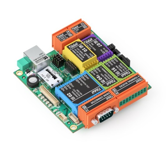
Tibbits (as in “Tibbo Bits”) are blocks of prepackaged I/O functionality housed in brightly colored rectangular shells. Tibbits are subdivided into Modules and Connectors.

Want an ADC? There is a Tibbit Module for this. 24V power supply? Got that! RS232/422/485 port? We have this, and many other Modules, too.

Same goes for Tibbit Connectors. DB9 Tibbit? Check. Terminal block? Check. Infrared receiver/transmitter? Got it. Temperature, humidity, and pressure sensors? On the list of available Tibbits, too.

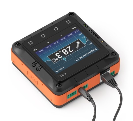
Assemble into a Tibbo Project Box (TPB)
tumblr_inline_o0sdd7G0VI1qa8p5v_540.jpg


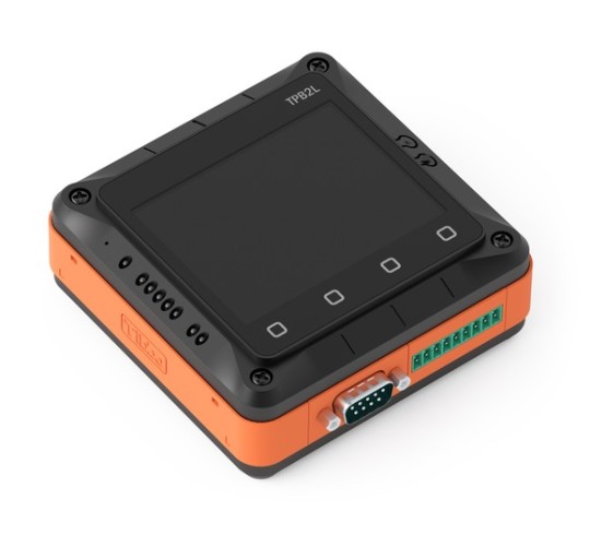
Most projects require an enclosure. Designing one is a tough job. Making it beautiful is even tougher, and may also be prohibitively expensive. Finding or making the right housing is a perennial obstacle to completing low-volume and hobbyist projects.

Strangely, suppliers of popular platforms such as Arduino, Raspberry Pi, and BeagleBone do not bother with providing any enclosures, and available third-party offerings are primitive and flimsy.

Tibbo understands enclosure struggles and here is our solution: Your Tibbo Project System can optionally be ordered with a Tibbo Project Box (TPB) kit.

The ingenious feature of the TPB is that its top and bottom walls are formed by Tibbit Connectors. This eliminates a huge problem of any low-volume production operation – the necessity to drill holes and openings in an off-the-shelf enclosure.

The result is a neat, professionally looking housing every time, even for projects with the production quantity of one.

Like boards, our enclosures are available in two sizes – medium and large. Medium-size project boxes can be ordered in the LCD/keypad version, thus allowing you to design solutions incorporating a user interface.

Unique Online Configurator

To simplify the process of planning your TPS we have created an Online Configurator.

Configurator allows you to select the Tibbo Project Board (TPP), “insert” Tibbit Modules and Connectors into the board’s sockets, and specify additional options. These include choosing whether or not you wish to add a Tibbo Project Box (TPB) enclosure, LCD and keypad, DIN rail mounting kit, and so on. You can choose to have your system shipped fully assembled or as a parts kit.

Configurator makes sure you specify a valid system by watching out for errors. For example, it verifies that the total power consumption of your future TPS device does not exceed available power budget. Configurator also checks the placement of Tibbits, ensuring that there are no mistakes in their arrangement.

Completed configurations can be immediately ordered from our online store. You can opt to keep each configuration private, share it with other registered users, or make it public for everyone to see.

Develop your application
tumblr_inline_o0sdfgvt6R1qa8p5v_540.jpg


Like all programmable Tibbo hardware, Tibbo Project System devices are powered by Tibbo OS (TiOS).

Use our free Tibbo IDE (TIDE) software to create and debug sophisticated automation applications in Tibbo BASIC, Tibbo C, or a combination of the two languages.

To learn more about the Tibbo Project System please visit http://tibbo.com/tps.html

Read more…
3D Robotics

QGroundControl 3.0 released

7a4cfebc05d1bd88148433c16ab809335702e25a_1_690x431.png

From the APM discussion group:

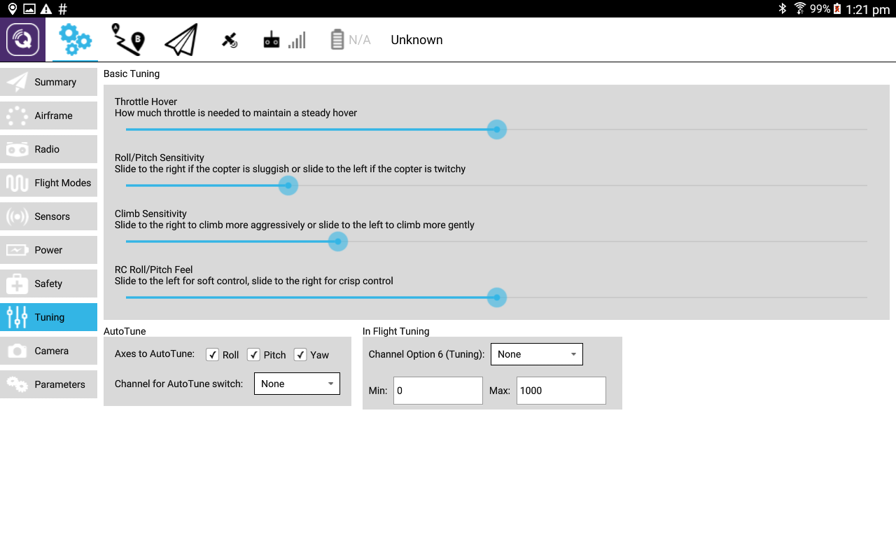
We are happy to announce the release of QGroundControl 3.0. QGroundControl provides full flight control, mission planning and configuration for ArduPilot or PX4 Pro powered vehicles. It is available for Windows, Linux, OS X, as well as Android devices (tablet and phone). Also with the release of QGC 3.0 comes beta availability of iOS support. The goal for QGroundControl is improved ease of use for new users as well as high end feature support for experienced users. Download links and user guide can be found here:http://qgroundcontrol.com

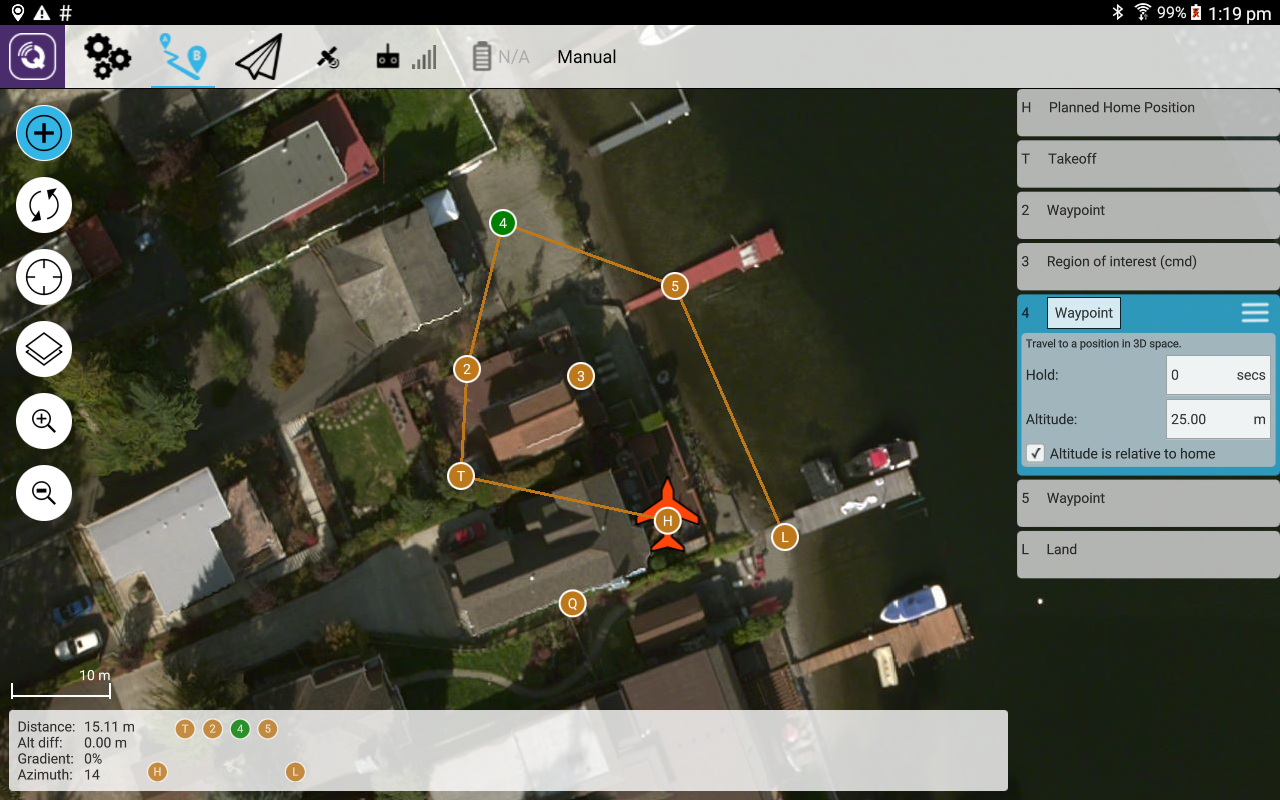
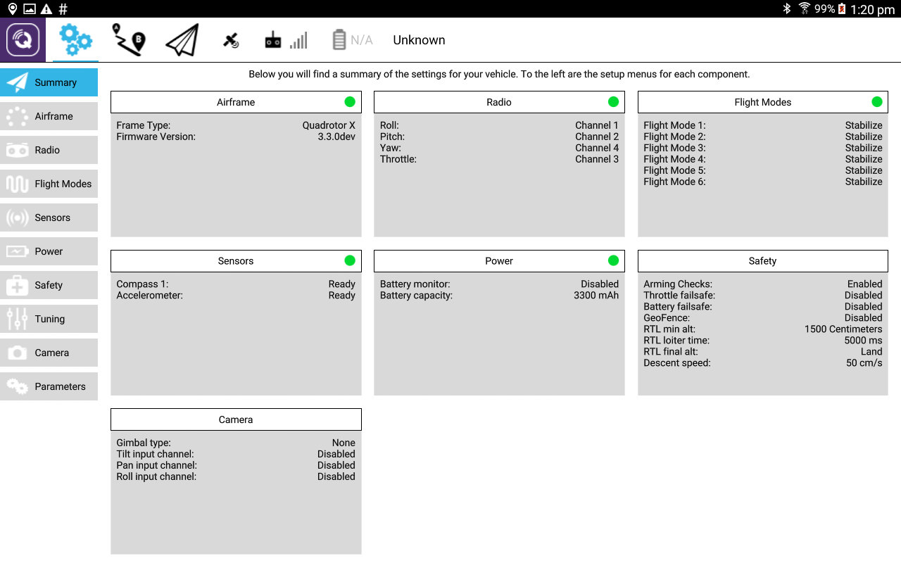
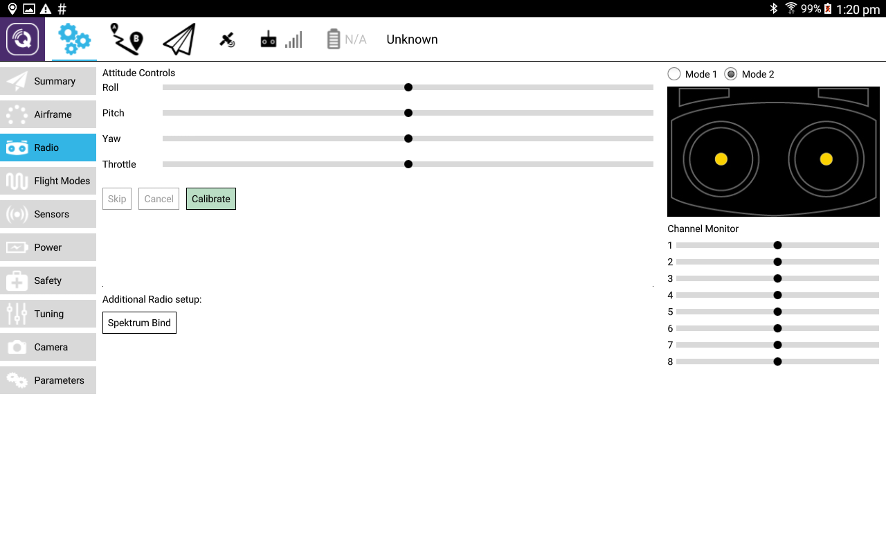
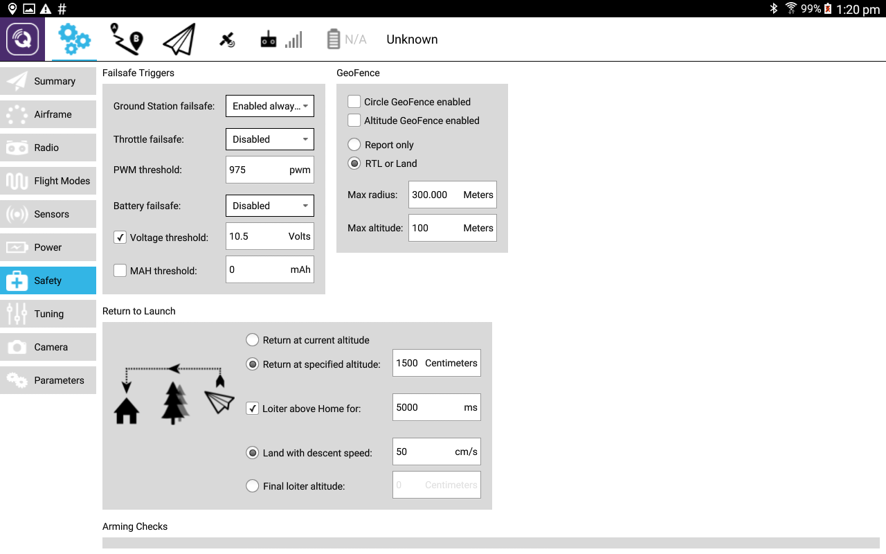
Screenshots from Android version:

Read more…
3D Robotics

3689697166?profile=originalCool report this morning from NBC's Today Show: Microsoft's Project Premonition is using 3DR Solos to find mosquito breeding areas, then putting "smart traps" there. Those traps (shown below) can analyze the DNA of the mosquito to see if they're carrying the Zika virus.  This already deployed in Houston, Texas, where the first Zika transmissions have been reported in the US.

3689697142?profile=original

Watch the whole segment here. 

Read more…

Age of Drones International Conference

3689697153?profile=original

The most professional speakers of UAV market will meet you on Age of Drones International Conference! Only the latest market trends will be discovered.
The program agenda will include the most important topics in four main sections:


- Legislation section;

- Photo&Video;

- Business section;

- Technical section.


Photo&Video Section will be presented by Matt Bjerregaard, Conservation Scientist and Drone Operator of BBC and National Geographic Channel, who will talk about drone cinematography and biodiversity. Another representative of this section, Jakub Karas, Partner in Upvision and Director of Czech Unmanned Aerial Alliance, is going to share tips about how to film with drone in extreme conditions.
Kay Wackwitz, CEO&Founder of Drone Industry Insights, and Thomas Gorski, founder and team captain of Airteam, are going to speak about UAV market trends and changes.
Besides this, you could find out how to avoid legal risks when using camera drones with Alexander Schmid, our expert of the Public Law, Security Law and Internet Law.
See more news very soon. Do you have something important you would like to share with UAV market? Send us your propositions: info@ageofdrones-expo.com
Join the community of world leaders right now: http://www.ageofdrones-expo.com/program/conference.html

Read more…

Aeriel Cinematography - Build or Buy

3689697042?profile=original3689697072?profile=original3689697113?profile=original

I've been traveling around the world the past couple years and on/off of it's occurred to me that it'd be great to have a drone to get some of the crazy shots at especially scenic locales.

The latest generation of consumer drones are almost there - the Phantom 4 and (to a lesser degree) the Yuneec Typhoon H PRO have decent image quality in a small package (1.4kg, 2kg respectively). As a photo/video geek however, tiny sensors with middling dynamic range, rolling shutter, and substandard bit-rates rankles. Having the flexibility of mounting a higher quality payload like the BMMCC, or a 360 solution like the 360fly 4K would be much better.

The tradeoff for DIY drones is that while adding payload flexibility (and a potentially better travel form-factor), they seem to have fallen behind AIO devices in terms of flight/camera automation.

$1399 - Phantom 4 Positives:

  • A very nice phone/tablet UI that includes smart drone and camera control as well as video.
    • Tap to fly
    • Optical object tracking (ActiveTrack)
    • Orbit mode
    • While it doesn't have explicit "cable cam" modes, you can course lock and set waypoints and manually control the gimbal
  • Lightbridge is a 2.4GHz digital Wimax-like protocol that advertises 5km range and does integrated transmit, telemetry, and video (220ms latency)
  • Has stereo-optical frontal sense and avoid and active obstacle avoidance
  • It also has a downward facing camera and ultrasonic sensors that give it best-in-class low-altitude hover
  • 1.4kg flight ready
  • Quick release rotors

Phantom 4 Gotchas/Mods:

  • Replacing landing gear - the form factor isn't ideal for strapping on the back while hiking, this, and landing gears in the shot can both be fixed by replacing the default skids w/ retractable landing gear (see also: 1, 2, 3, 4, 5, 6)
  • The gimbal/camera is quite complex looking, hasn't been reverse engineered, you're likely stuck w/ it
  • You can probably take the Phantom apart and weatherproof it (CorrosionX everything); it may be possible to replace the lens

$1899 Yuneec Typhoon H Pro/Realsense:

  • Sadly, it's almost not worth talking about this because while there are a many good things, the camera is terrible - it shoots a mystifyingly low bit rate (29Mbps vs the Phantom 4's 60Mbps) and doesn't have a true flat profile. The default lens is super-crappy and focused improperly, so if you buy one, consider a lens upgrade mandatory.
  • The Typhoon H is a hex, and can fly if a motor/prop goes out. It also has quick release rotors.
  • It comes with a retractable landing gear and allows 360 motion on the gimbal out of the box, but that doesn't help portability much - the arms fold down, making a big cylinder that's probably not the most convenient thing to carry.
  • The ST16 controller is quite large, but integrates an Intel Atom touch screen system into the controller w/ 1080P transmission w/ <200ms latency all via a custom 5.8GHz (802.11ac-like?) protocol (1.6km range)
  • It uses front-facing ultrasound and Intel Real Sense camera for obstacle avoidance
  • Camera modes:
    • Orbit Me
    • POI
    • Journey (selfie)
    • Curve Cable Cam (preset curves for flight and camera position via waypoints)
    • Watch Me/Follow Me (GPS)

And of course, there's the DIY Drone option. I will probably end up here, since I've started going down the rabbit hole here, but some thoughts.

First, portability is the pretty key here. Although flying weight will probably be a bit heavier than the Phantom 4 (just over 2kg), we can build a drone that can lift over 1kg of payload that packs up to about the size of an A3 piece of paper using an Alien 680 frame (Skylark, H4/H4).

Above is what it looks like folded up

The foldable props are particularly sexy.

For travel, separate servoless retracts is probably the way to go, but life may be easier w/ some known standard retracts.

We're of course responsible for our own camera/payload here. I have a Point Grey Grasshopper 3 lying around that'd be worth trying to get to work. Notably, it has a Sony IMX252 sensor which is FHD+, 120fps+, has a global shutter, and about 12 stops (72dB) of dynamic range, far better than the DJI/Yuneeq cameras assuming I can get something reasonable to record with (ideally an XU4, MinnowBoard MAX, or less ideally, a TX1/J120).

In addition to that we'll need a gimbal. Variations of the Alexmos/SimpleBGC controllers seem to be the most common/well known. This undoubtedly requires some more research, but there's no end of control/programmability there.

The same lightweight gimbals should be usable for mounting something like the Fly360 4K.

Gimbals that can handle heavier setups (BMMCC, other m43 cameras) are more expensive and heavier, but should be doable. (if my eCalc numbers are accurate)

You can of course spend a lot of time working on the power train. I'm almost tempted to buy some motors and a testbench simply to confirm some of these, but there's no point over-optimizing before doing a build, I suppose.

Lastly, and most importantly perhaps are the navigation bits.

There's plenty of 915MHz telemetry modules that are quite cheap, although it might be worth considering a DragonLink for ridiculous range, handling the RC transmission, and bt connecting to handhelds.

The UBLOX M8N GPS modules seem pretty standard and can be bought for dirt cheap (cheap one w/ EMI protection), you might benefit from a really large pro version (or an expensive smaller one) - there's a tiny comparison here. For those serious about their GNSS it looks like Emlid's Reach is pretty cool (DrotekandPiksi are two others)

For the Pixhawk flight controllers, two good options look like the PixRacer which has slightly newer sensors and built-in wifi, and the PixFalcon which has a failsafe mc and some extra power filtering. Both are pretty tiny.  (I'm still researching whether it's worth going with the newer RPi-based controllers like the Erle-Brain 2 and Navio2 - right now it may be better/worth it to simply connect a separate board via MAVLink for more complex stuff, but have a more reliable mc for basic flight controls).

My initial plan for video transmission is to use an analog 5.8GHz transmitter w/ HDMI support, but the Amimon Connex Mini looks pretty darn cool (1080p60 @ 1ms latency, 500m range).

Ultimately, I'd like to primarily use autopilot/telemetry for most of the flying, and at the very least reduce radios (the DragonLink would combine the telemetry and RC control), but RC control, at least for a backup/emergency is of course required.  This is probably it's own project, but it seems like it'd be possible to build a tinyduino/PPM+receiver+minjoystick 2/4-channel doohickey.  Until then, a janky $15 controller might be the most compact option.

Obviously, just about everything for this setup requires some work, but the big projects for me would be:

  • optical-flow/object tracking/gimble movement (optical follow me)
  • gimble/camera direction waypointing (curved cable cam)
  • laser/sonar obstacle avoidance/stability
  • fly-by-telemetry (radio/control reduction)

For those interested in a parts list/notes:

https://docs.google.com/spreadsheets/d/1TkPLaImvb76bMIvJKKhjp9y2UGUzCGRrSXMRtdTIkas/edit#gid=0

My plan is to start putting some of this together when I get back in the US in Sept/Oct

Read more…

Update, 8/2/2016:

After reading some posts below, I think it *might be* okay for me to put up the general book description and the ToC. If this is not okay--that is, an advertisement, only--I'm sure I'll find out. The book's Preface and sample pages may be obtained at its landing page within the SPIE website.

Best to all,

Barbara

***************************

Book Description:

Getting Started with UAV Imaging Systems: A Radiometric Guide provides the tools technologists need to begin designing or analyzing the data product of a UAV imager. Covering the basics of target signatures, radiometric propagation, electro-optical systems, UAV platforms, and image quality, it is replete with examples that promote immediate application of the concepts. Reference materials at the end of each chapter, including many links to current systems and platforms, offer further guidance for readers. Engineers and scientists who specify instrument requirements; design, build, or test hardware; or analyze images for commercial, scientific, and military applications will find the book a useful addition to their working library.

Table of Contents

Preface

List of Acronyms and Abbreviations

1 Introduction
1.1 UAV Imaging: A Disruptive Innovation
1.2 Components of a UAV System
1.3 Size, Weight, Power, and Platform
1.4 Terminology and Acronyms
2 Radiometry of Targets: Emission and Reflection
2.1 Introduction
2.2 The Electromagnetic Spectrum
2.3 Emission and Reflection within Spectral Regions
      2.3.1 Overview
      2.3.2 Emission
      2.3.3 Reflection
References
3 Radiometric Propagation Basics
3.1 Plane Angle and Instantaneous Field of View
3.2 Solid Angle and Projected Solid Angle
3.3 Radiometric Terms and Their Units
      3.3.1 Radiance
      3.3.2 Irradiance
      3.3.3 Radiant exitance
      3.3.4 Radiant intensity
      3.3.5 Summary of radiometric terms and units
      3.3.6 Summary of the terms, in photons
      3.3.7 Imaging spectroscopy and wavenumber
3.4 Relationships Important to Propagation Calculations
      3.4.1 The inverse square law of irradiance
      3.4.2 Intensity and radiance relationship
      3.4.3 Conclusion
References

4 Imaging System Basics
4.1 Introduction
4.2 The Camera Equation and Image Plane Irradiance
4.3 Terms and Definitions Relating to Image Acquisition Geometry
      4.3.1 Elevation angle
      4.3.2 Sensor relative elevation angle
      4.3.3 Sensor relative azimuth angle
      4.3.4 Horizontal and vertical fields of view
      4.3.5 Ground sample distance
      4.3.6 Slant range
4.4 General Description of Optical Systems for UAV Imaging
4.5 Spectral Imaging
4.6 Calculating the Signal from the Focal Plane: A Multispectral-Channel Example
4.7 Noise Equivalent Power
4.8 Noise Equivalent Radiance
4.9 Noise Equivalent Irradiance
4.10 Noise Equivalent Reflectance Difference
4.11 Modulation Transfer Function
References

5 Platforms, Sensors, and Applications
5.1 Introduction
5.2 Large Military Platforms
5.3 Small UAV Platforms
      5.3.1 SWaP-C and sUAS
      5.3.2 UAV swarm: the smallest platform/sensor subtype
      5.3.3 Factors that influence platform selection
      5.3.4 Pointing the payload
5.4 Platform and Application Examples
      5.4.1 Distinguishing between two objects at UAV altitude
      5.4.2 Near-infrared and SWIR imaging comparison
      5.4.3 "Day/night" imager and covert illumination
      5.4.4 Uncooled thermal microbolometer
5.5 Thermal Contrast
5.6 Noise Equivalent Temperature Difference
      5.6.1 NETD expression for energy units
      5.6.2 NETD in terms of photons
5.7 Minimum Resolvable Temperature Difference
References

6 The Image Data Product and Quality Metrics
6.1 Introduction
6.2 Imagery Authentication
6.3 Metadata
6.4 Video, Motion Imagery, and Full Motion Video
6.5 Video Scan Types
6.6 Definition in Lines per Frame
6.7 Image Quality Scales
      6.7.1 Introduction
      6.7.2 Motion imagery: video NIIRS
      6.7.3 Still imagery: NIIRS and IIRS
      6.7.4 Predicting NIIRS: the general image quality equation
6.8 Probability of Discrimination
      6.8.1 Johnson criteria and target transfer probability functions
      6.8.2 Probability calculations
      6.8.3 Comparison with the NIIRS criteria
6.9 Atmospheric Correction
      6.9.1 Introduction
      6.9.2 Atmospheric windows and narrow bands
References

7 Detectors for UAV Imaging Systems
7.1 Introduction
7.2 Photon Detectors
7.3 CCD and CMOS
      7.3.1 CCD basics
      7.3.2 Color CCDs
      7.3.3 CMOS basics
7.4 Thermal Detectors
      7.4.1 Thermal detection basics
      7.4.2 The microbolometer
7.5 Detector Noise Sources
      7.5.1 Johnson noise
      7.5.2 Shot noise
      7.5.3 Generation-recombination noise
      7.5.4 Temperature fluctuation noise
      7.5.5 1/f noise
      7.5.6 Photon noise
      7.5.7 Quantization noise
      7.5.8 Additional detector noises
      7.5.9 Noises in arrays
References

8 Conclusion
Appendix A SI Base Units and Derived Quantities
Appendix B Concise Notation, Uncertainty Reporting, and CODATA 2014 Physical Constants
B.1 Reporting Uncertainty
B.2 Pending Changes in Values of "Constants"
Appendix C Drones and the Law
C.1 Commercial Use of Drones and FAA Regulations
C.2 Security, Privacy, and Law Enforcement Issues
Appendix D The Need for Standards in UAV Imagery Analysis
D.1 Connecting the Dots
D.2 Marking the Scorecard
Index

**************************************

After carefully considering the commentary generated by my post, announcing my new UAV imaging system book, I have decided to delete the post and its link. Interested potential readers may Google my name and "drones" to find the website where it may be ordered. (They may also find my website. I have a _lot_ of experience explaining technical concepts, even in non-technical venues.)

I did, of course, read the TOS before posting; but didn't realize that the issue was this dicey. Many thanks to those who found my post interesting and relevant.

Here's part of my philosophy: I've been in the optics community for about 30 years. We don't do that great of a job of outreach to the broader world where talented individuals are working on innovations that may benefit from the knowledge we have. In fact, many of our books and other publications are written strictly for our professional peers, and never find their way outside the university.

With UAV imaging, I sought to broaden that reach by designing my book to be as practical, and as applied, as possible. One should have an engineering/physics/or scientific background to understand every single detail; but smart individuals with even a high school physics understanding will benefit from it, I believe.

Before the book was published, I spoke to my publisher about my desire to attract a wide audience; I believe that review copies were sent to UST Magazine and Wired, as well as to our usual optical engineering/optical science publications.

My hope, I said, was that the work would come into the hands of individuals already working on drones, but without the background knowledge in fields of my expertise. I still hope so. Putting the two together will increase the disruptive potential of UAV imagers and further grow the industry and applications markets.

Best, to all.

Read more…
MR60

DALRC XR215 V2 FPV Racer Build

Hi,

As a follow up of my latest blogs about FPV hardware, here is a build video. The build is made with the following components:


-DALRC XR215 V2 Full Carbon Fiber Quad Frame for FPV Racing FPV Build in OSD BEC BB Ring: http://goo.gl/dcIW2V

-Foxeer XAT600M DC5V-22V 600tvl Sony Super HAD CCD FPV Camera: http://goo.gl/ETYdS0

-Gearbest kindly provided motors for this project, Emax RS2205 2300KV Racing Edition : http://goo.gl/mV4P5h

-ESCs are taken from Gearbest's Flycolor Fairy Series V2 20A BLHeli ESCs : http://goo.gl/RU8b36

-F3 Flight controller Deluxe was kindly provided by Gearbest for this build : http://goo.gl/CDDK3C

-Propellers are DALprop J5040 : http://goo.gl/huUCeE

-ESC firmware is BLHeli with oneshot125 downloaded and flashed with the BLHeliSuite software (latest version)

-F3 flight controller firmware is Betaflight (latest version) downloaded and installed via the Betaflight configurator (Chrome app)

Music by Kevin MacLeod - site = http://incompetech.com/

Disclaimer : no chickens were hurt in the making.

Read more…

Ultra - stick style UAV platform

3689697498?profile=original

Thought I would share one of my recent projects. I am designing an ultra stick style UAV platform designed to carry a 3 axis mini 3D pro brushless gimbal for smooth fpv video while the aicraft carries out an autonomous mission. 

The construction uses lasercut balsa and lightply so it will be extremely cheap and easy to make, while the wing is hotwire cut out of eps and then skinned with a sheet of 1mm balsa for stiffness. 

I designed the wing using a constant airfoil section (NACA2414) with washout towards the tip so wing produces an elliptical lift distribution which will greatly improve stall characteristics. 

The wing is designed to fly at 16m/s (around 60km/h) if the airframe is kept at 2kg. so things need to be kept light. 

3689697513?profile=original3689697569?profile=original3689697534?profile=originalLet me know what you think!

Read more…

Work in progress : Indoor light track

Hi,

I wanted to share with you our latest work in progress on lighting technologies for drone racing.

This is just the beginning but it look already amazing :)

I hope you'll enjoy it !

I've you're interested in such technologies feel free to contact me.

Read more…
3D Robotics

Swarming with Solos and ROS

I've posted a bunch of teaser videos of the Solo swarming we do often at 3DR, but have not yet posted instructions on how to do it yourself -- I was just waiting for the team to document the steps. Well good news: now they have!

The above video (sorry for the shaky camera -- we were excited) shows a fun exercise in in using the Solo drones to autonomously play Pong with themselves. Each "paddle" is made up of two Solos. The "ball" is the fifth. All this is automatically controlled by ROS, running on the ground. Instructions on how to do this are in the documents below.

Instructions:

Enjoy!

Read more…

3689697012?profile=original

This post first appeared in sUAS News ‘The Market’

---

According to 2015 statistics from the US Department of Labor, there are 44,300 surveyors in the United States. But mapping is practiced by a larger population of cartographers, topographers, photogrammetrists, civil engineers, and geographers – it’s not exclusive to the surveying industry.  The American Society of Civil Engineers lists more than 150,000 members in 177 countries, and the Imaging and Geospatial Society has 7,000 supporters.  All of these disciplines can be grouped under a broader category called geographic information systems (GIS).  GIS professionals provide a wide variety of land-related services like identifying property boundaries, subdividing land, and surveying construction sites for placement of buildings. They also produce topographic and hydrographic maps, volumetric calculations for stockpiles, and flood insurance maps, among other services. 

The number of surveyors is actually projected to decline by two percent from 2014 to 2024 because of improved surveying technology.  Even though surveyors are a fraction of the broader population of GIS professionals, how will the improved surveying technology that is affecting them apply to that broader GIS population? And given the downbeat forecast for surveyors compared with the numerous upbeat billion dollar projections of drone use from the FAA and other industry observers, the question becomes, Where do commercial unmanned aircraft systems (UAS) or drones fit into the surveying technology mix?

With those questions in mind we just completed a study titled “The Truth About Drones in Mapping and Surveying,” The report is the fourth in series of studies that look objectively at each major commercial market for drones and drone technology. This report is co-authored by Bill McNeil, Contributor / Advisor, and Colin Snow, CEO and Founder, Skylogic Research, LLC, and it shows how small drones have been used successfully in surveying and mapping thus far and outlines the lessons learned. It goes on to discuss the opportunities and challenges for GIS professionals, reviews competitive and traditional approaches offered by incumbent technology, and discusses what’s next for drones in this sector.  Here is an excerpt:

“Drones are going to have a major impact on the surveying and mapping industry, but perhaps to a lesser degree on traditional surveyors.  As mentioned earlier, the Department of Labor is forecasting a 2% drop in the number of surveyors from 2014 to 2024.  On the other hand, the Labor Department is projecting 29% growth for the photogrammetry category.  This means more and more photogrammetrists will do surveying work and more surveyors will use photogrammetry tools for mapping.  In other words, inexpensive data collected from drones has and will continue to blur the lines between photogrammetry and mapping.

There is another issue at play here.  The process of physically flying a drone is not unique to map making.  The type of data collected is determined by the instrument payload -- not by the drone operator.  In other words, it really doesn’t make any difference if the application is precision agriculture or mapping a pipeline, the deliverables are the information extracted and processed by the crop consultant, the photogrammetrist, or the surveyor.

Drone technology is moving extremely fast.  It’s very possible many surveyors would rather hire a service provider to collect data than invest in a tool that can be obsolete is as little as six months.  They may also consider short-term leases to ensure their technology is relatively current or just rent a drone when needed.  Regardless of how small drones fit into the workflow, they will not only affect the industry, but they will also create new opportunities for independent contractors who, based on their experience, may be able to fly and collect data less expensively than surveyors.  The value add is the knowledge and data processing skills of the surveyor and photogrammetrist, not their drone-flying skills.”

You can get the free report here.

If you have questions about what's in the report or would like to comment on it after reading it, comment here or write me colin@droneanalyst.com.

Image courtesy of BZ Media.

Read more…

In this post I show videos of two real flights, the first above for FlightZoomer version 2.0 and another below with the freshly released version 2.1. Both videos show the same automatic flight including an ILS approach. In the videos the replay feature is used to sync the recorded video from the on-board Sony camera with the presentation of the groundstation.

While FlightZoomer 2.0 works nicely and was a huge step forward overall, the video also shows some areas, that leave room for improvement. In particular the LNAV, the VNAV and the ILS autopilot modes worked not as precisely as a Pixhawk based system in theory could.

All this was addressed with FlightZoomer version 2.1, so check out the following video to see how the behavior improved:

Version 2.1 is provided as a functional upgrade. It does not bring a single new button or any UI change, but under the hood a nice number of improvements have been implemented. Existing algorithms have been refined, new cascaded control layers have been added, the ILS can be captured much more robustly, flight plans are followed more precisely and a bunch of bugs have been ironed out.

The complete list of changes is here:

  1. The turn initiation time is considered now for the flight path calculations. The turn initiation time is the duration, during which the flight path over ground lags the ideal turn. This change increases significantly the precision, how the aircraft follows the planned flight track.
  2. For the LNAV and the ILS Localizer mode deviations along the straight legs are now actively corrected. Prior version 2.1 the aircraft always just pointed to the next waypoint and, as a result, deviations have not been corrected until the very end of each leg.
  3. A new algorithm has been implemented in LNAV mode to keep the turn radius constant even if the speed varies a bit. This was required because before the aircraft often deviated from the planned track during turns when the speed was dropping temporarily.
  4. Speed transitions have been abruptly prior version 2.1 but now are smooth as well. Every speed change happens over a period of 2 seconds.
  5. The vertical flight profile in VNAV mode has been improved. Due to inaccuracies in keeping the standard climb or descend rate, the actual altitude could deviate quite a bit from the correct altitude for a certain position. This is important especially during descends because we are moving towards the terrain and because the end of the descend and the end of the route should happen exactly at the same spot. The new VNAV algorithm in version 2.1 ensures this.
  6. Optimization and fine-tuning of the approach pattern calculation. The result is a more realistic and much more compact approach pattern, especially during the downwind and base.
  7. The ILS glideslope can now not only be captured from below and after having turned to the final approach course, but from below or even before the last turn.
  8. Totally 26 issues have been fixed.


In both videos basically the entire flight was flown with the autopilot. Along the route using the LNAV and the VNAV modes, using the TRACK OVER GROUND, ALTITUDE and FLCH modes for the downwind and base and finally using the ILS LOCALIZER and ILS GLIDESLOPE modes for the approach.


Some screenshots from the second video:

On the next image you can see how precisely the aircraft follows the planned track even during a turn. Consider that the turn radius first is a variable that depends on the cruise speed and the turn rate (angular velocity). In practice also the actual speed and the impact of the inertia on the actual track over ground have to be incorporated:

3689696896?profile=original

The second image shows the final approach to the runway 08 of my virtual airport. Consider how the runway elevation has been configured 5 m above the real road, in order to have some safety buffer:

3689696915?profile=original


Again I dont want to miss the opportunity to provide some high level information about FlightZoomer:

  • FlightZoomer is a top notch distributed avionics suite for drones
  • FlightZoomer is entirely a software solution. The hardware are COTS devices (Windows Phones smartphones).
  • Why distributed? Because there is an onboard device and a groundstation, both are connected via a Relay Server at home.
  • All the components are coupled with a cellular EDGE, 3G or 4G link.
  • The onboard smartphone is mated with an APM based flight controller via Bluetooth.
  • Currently supported is Arducopter 3.3 or higher.
  • Supporting Arduplane is on the to-do list.
  • For about 200$ you can get everything mentioned working (assumed, you need to buy two Windows Phones for the groundstation and the sensor device)


Much more details you can find on my homepage flightzoomer.com.


The full documentation for version 1.5 is still valid for the basic functionality:

Version 1.5 full documentation


For the version 2.0 the additional features are described in this 50 page addendum:

Version 2.0 addendum


For version 2.1 there is currently no separate documentation (beside this post :D ) 

Read more…
Developer

AntennaTracker v1.0 on NAVIO2 with Bebop2

ArduPilot's Antenna Tracker firmware has been making some quiet progress over the past few months.  They're all documented in the Release Notes but at a high level the improvements include:

  • More accurate control due to bug fixes in how the vehicle's position estimation was done
  • Smoother movement through additional filtering
  • Separate servo types possible for yaw and pitch axes
  • Tilt compensation meaning it tracks the vehicle accurately even when the tracker is leaned over
  • Improved Mission Planner setup screen (i.e. Extended tuning page)

The parts I used to build my tracker included:

I used a NAVIO2 instead of a Pixhawk mostly because it's easier to make a Wifi connection this way.

I haven't yet tested the range of the telemetry connection to the Bebop2 but I suspect it's between 1km ~ 2km.  In fact, the antenna used here is not ideal for use with the Bebop2, a simpler non-Helical antenna like this one would likely do better.

Some limitations of this setup:

  • we don't yet support receiving live video from the Bebop2 but this is coming within the next couple of months so during this test I simply had telemetry data from both Tracker and Bebop2 visible in the Mission Planner
  • the networking connection between the PC to the RPI2 was quite simple but not very flexible.  For whatever reason the PC and RPI2 nearly always appear with the same IP addresses so the Tracker startup scripts were hardcoded to always uses these.  It would be better to setup dhcp on the RPI2 to set PC's IP address
  • the bebop's Wifi ssid is hard-coded in the start_tracker.sh script on the RPI2.  If someone wanted to repeat this setup they would need to change this to match their particular Bebop.

In case people want to replicate this setup, I've uploaded an image to firmware.ardupilot.org here.

Thanks to the beta testers for their ideas and feedback and Stefan Lynka for his code contributions.

3689696965?profile=original

Read more…

We've recently been pushing the low cost Raspberry Pi Zero to see what it can handle.

With a custom Raspbian linux build with real-time patches, Martin Evans ( @lostcaggy on Twitter ) has managed to get a slightly modified version of Ardupilot up and running on a Pi Zero controlled RC buggy using our (Dark Water Foundation) Escape board to control the motor and steering servo and transmitting video, GPS and IMU details back to QGroundControl.

The Buggy is being used to test the hardware and software before it's loaded into a boat (old used Kayak) and sent out to survey the oceans (probably closer to shore though :) ) - https://hackaday.io/project/12484-the-julius-project

Above is a short video showing its second run.

The Escape board is currently on Kickstarter - ending very soon.

Read more…
3D Robotics

I've backed it. Similar concept to what we're doing at go-kart scale, but without the GPS and other big-car stuff. On Kickstarter now. 

Formula Pi is an exciting new race series and club designed to get people started with self-driving robotics. The aim is to give people with little hardware or software experience a platform to get started and learn how autonomous vehicles work.

We provide the hardware and basic software to join the race series. Competitors can modify the software however they like, and come race day a prepared SD card with your software on it will be placed into our club robots and the race will begin!

You don't need to be in the UK, you can enter the series from anywhere in the world. Just join and send code to compete!

Formula Pi YetiBorgs on trackFormula Pi YetiBorgs on track

The Series

The series will consist of races hosted here at PiBorg. The races will be live broadcast for everyone to watch online. Races will consist of up to 23 laps (approximately 1/2km) with 5 competitors per race. The robots will be provided by PiBorg for racing.

Grid position, competitor list and club robot assignments are assigned with a random shuffle script.

Each competitor will be involved in a minimum of 5 races. We will have a complete structure once we know how many competitors are involved.

Anticipated race dates

Although these dates may change (especially due to amount of entries), we expect the following:

Winter series - from October 2016 - January 2017

Summer series - from April 2017 - July 2017

Formula Pi YetiBorgs ready to startFormula Pi YetiBorgs ready to start

The Track

The track was designed and built at the PiBorg offices. The 22.9m track has 5 corners and can be run in either direction. There is a built in timing rig and start lights to control the race. The colouring of the track helps the software identify changes in direction.

Formula Pi track #1 - PiBorgFormula Pi track #1 - PiBorg

The Robots

The YetiBorg HS Zero robots are a new design and will include our already successful ZeroBorg Kickstarter for motor control. The 2mm thick Aluminium chassis are made here at PiBorg.

YetiBorg 2mm aluminium chassisYetiBorg 2mm aluminium chassis

When entering the races you will have a YetiBorg top (called a YetiLid). This is a fibreglass lid with a microsd card slot in it to conveniently store your code when shipping your top. The YetiLids will need to display a unique number for us to identify you and you can decorate your top to make sure you can see your robot.

YetiLid - top for your YetiBorgYetiLid - top for your YetiBorg

The Software

We have written a basic control software which will be available to use. This will be available on the Formula Pi website and on github. The software can be modified by the competitors to improve performance. Or you can provide your own software if you like! It can be as simple or complex as you want.

The winners code is published at the end of the season, so everyone can start the next season from an equal standing. This helps the autonomous software improve and makes for a highly competitive sport.

History of Formula Pi

It took a lot of testing ideas and programming lots of different code before we got good results. Our very first run was less than successful! We eventually decided that if the track was painted in bright colours, the robots could dedicate more time to processing things such as the position of other robots, collision avoidance, traffic light detection and so on.

project video thumbnail

Project status

We are ready to go racing with the exception of having a fleet of performance calibrated YetiBorgs for the club robots! This Kickstarter would allow us to buy resources to build robots for competitors to use for racing. The more successful we are, the more competitors we can host.

The track has been mostly built, but is missing a timing rig. We have a laser timing rig that we developed for Pi Wars and we will be adapting this with a Pi 3 and Pi Camera to take images of the cars as they pass the start/finish line. We can also use this to check for jump starts.

We are intending to buy basic cameras to allow us to broadcast the races on a platform such as Youtube. And this way we can capture all of the action on track and record the races for you to enjoy at any time.

The software is mostly ready, we still need to do a few tweaks here and there. We are working on blog material at the same time as coding, so you can see what we have done and why.

We have a domain and website dedicated to this project at www.formulapi.com where you will find rules, code and all sorts of useful information.

Formulapi.com blogFormulapi.com blog

The Rewards

The rewards vary from race entry with a YetiLid to the YetiBorgs themselves. The YetiBorgs are high quality robots which can take the bumps and rubbing of racing.You don't need to have one to be part of the racing, but you might want one to experiment with autonomous robotics or just to drive like an RC car! They come with everything you need with the exception of a 9V battery and a Raspberry Pi Zero.

YetiBorg Raspberry Pi Autonomous robotYetiBorg Raspberry Pi Autonomous robot

They are made from 2mm thick aluminum and they have high quality metal gear motors similar to a DiddyBorg motor. They also sport the ZeroBorg motor controller we had for our last Kickstarter.

YetiBorg high quality motorYetiBorg high quality motor

The YetiBorgs are supplied with detailed build instructions and our normal high standards of PiBorg support. As always, if there are any problems with building or getting started, we're there to help on our PiBorg forum

YetiBorg build instructionsYetiBorg build instructions

This together makes an awesome Raspberry Pi Zero controlled robot!

Read more…

3689697288?profile=original

Théa is the world’s first UAS to meet the high standards for an FAA Airworthiness Certificate, expanding its operational capabilities beyond those of any other commercial unmanned aircraft to allow legal flight over crowds, at night, and beyond. By providing unmatched aircraft-grade reliability (99.999 999 9%), Théa meets the stringent requirements necessary to go where consumer-grade systems can’t.

Théa has unmatched payload and flight-time capabilities, allowing you to do more

No PayloadFull Payload (11kg)
Weight (Ready to fly)27kg (60lb)38kg (83lb)
Flight time35 mins21 mins
Max Speed40kph (24mph)  30kph (20 mph)
Climb rate7 m/s5 m/s
Radio Range1500m
Operating Temperature120 to -20 deg F

Tech specs:
  • 1100mm Diagonal
  • 780mm x 780mm x 800mm unfolded
  • 29in props
  • 3 sets of high-power LiPo batteries
  • 4000w of charging power for continuous flight
  • Unmatched 99.9999999% reliability
Théa can handle the most demanding camera payloads, such as:
  • Canon C500
  • RED Epic X / Dragon
  • Sony FS7

Théa has unprecedented flexibility

  • Ability to fly at night, allowing you to capture striking footage
  • Can fly with weights above 55lb to carry the best camera equipment
  • Ability to fly beyond line of sight to capture footage that would be impossible to get otherwise
  • The ability to fly over uninvolved people like crowds and roads to allow you to go where you couldn't before

Continuing Support

​Support packages are available to back Théa’s unparalleled reliability with unparalleled service. We provide next-day guaranteed service, including required maintenance intervals for flight worthiness, as well as 24/7 support, so you never have to worry.
Contact us at: contact@enterprisedronesolutions.com
Read more…

3689696695?profile=originalAvailability of water for crops and their resistance to shortages during growth affect the overall yield, quality and profitability of field production in changing climate (Fig. 1). Plants affected by drought stress close their stomata, the process of transpiration that cools vegetation gets down and the surface temperature of the leaves increases up.


3689696830?profile=originalQuick detection and quantification of elements of varietal resistance to stress and quick detection and quantification of elements of surface variability of weak moisture are essential for the management of field crops. The data can be used for selection and delimitation of species and varieties of crops within enterprises. They can also be used for the purposes of precise farming, clarification of the moisture needs in irrigations, etc.

For scanning the temperature condition of experimental varieties, we used a thermal camera WIRIS supported by UAV platform (Fig. 2). The flight was pre-programmed using UGCS Ground Station. The data have been processed in the program Pix4D and analyzed by Workswell CorePlayer and Workswell Thermoformat.


3689696778?profile=original

Figure 3 shows the experimental lands and the experimental areas (the latter in detail) (1500 m2) (Figure 4), with tests aimed to the lines of winter wheat with different sizes of root system that would affect drought tolerance. Stress is induced by shading; the optimum content of water is maintained by dripping irrigation.


3689696866?profile=original

3689696695?profile=original

Analysis of data and their validation in semi-operating conditions (Figure 5) suggests new options for quantitative and qualitative evaluation of abiotic stress induced in the cereals due to lack of moisture. For the future application, there will be models based on exact measurements on the ground; the data which are scanned from the air shall be easily, quickly (Figure 6) and reliably interpretable even when based on the index of water stress in plants (CWSI) specific for particular varieties in the area of cultivation.


3689696851?profile=original

3689696792?profile=original

Note: Research was in cooperation of Workswell (vendor of thermal camera WIRIS), Vertical Images (UAV pilots) and Czech Crop Research Institute.

Read more…

3689696670?profile=original

As some of you may know, I have been working on a GCS for iOS devices called iMavlink.

It is currently in its final stages before release, but I would really like to have some beta testers to squish the final bugs.

If you are interested, I am currently selling the BLE Device that accompanies the app for $60 on my store.

This device is required for the app to work, you can create your own, however I cannot guarantee that it is supported. (If you do DIY, let me know if it doesn't work on the http://imavlink.com forum and I'll do what I can to implement support for it.

The app will be selling for $5.99 USD, however it will be free for the first 4 purchases of the BLE Repeater for beta testing purposes!

Thanks guys, please let me know if you have any questions! I have a website for the app at http://imavlink.com

Features:

  • GPS Location of drone
  • Set, edit and delete waypoints
  • Arm/Disarm
  • Display VFR information such as yaw, pitch and roll.
  • Voice alerts for mode changes and other important information
  • Edit Parameters
  • Log flights for future reference
  • GPS Status of drone
  • Distance from home/device
  • Battery voltage display and warnings
  • Calibration of battery monitor and accelerometer
  • Light and Dark themes
  • Manage multiple BLE Repeaters
  • And many more

Cheers!

Read more…

Silkopter FC Done

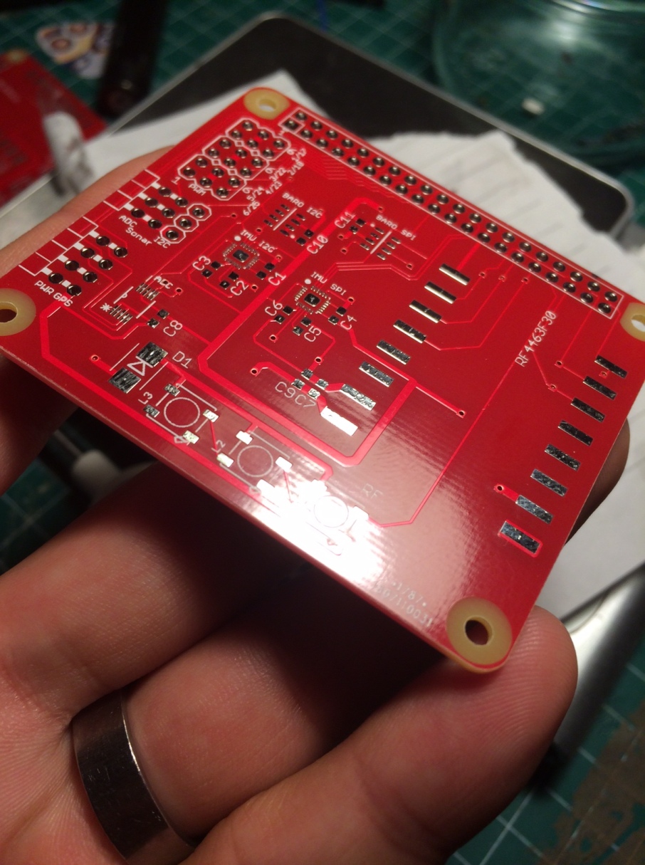
pcb

(You can check the progress (and a copy of this post) on my blog.)

Finally, after some DHL delivery trouble the boards arrived.

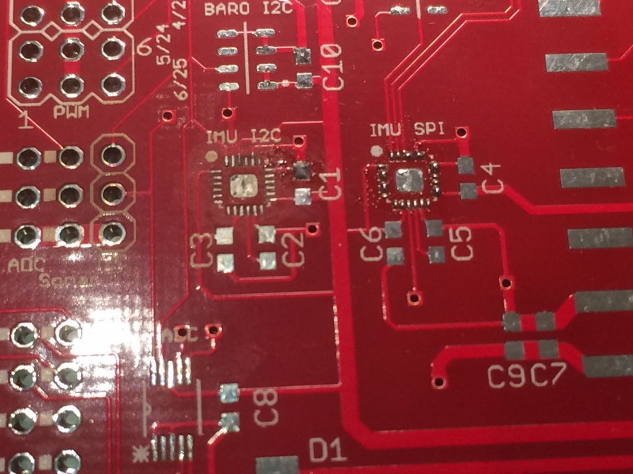
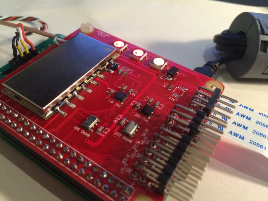
After watching a few tutorials I immediately tried soldering the most difficult part – the MPU9250 chip. Turns out – if you don’t have the right flux type it’s impossible. I managed to ruin 2 boards in the process and broken 1 chip…

broken pcb

Notice the PCB changing color next to the IMU I2C pins and the ‘dry’ look. The pin header holes are also darker than the others due to the heat.


2 days later my new flux came: Chip Quick SMD291 ordered from farnell. This time it went much better as I was able to solder 2 chips in 5 minutes, from the first try. The trick is that tacky solder flux doesn’t evaporate from the hot air and keeps the chip floating while the solder melts (and prevents oxidation). When the solder flows, the chip kinda snaps into place and that’s it. In my first tries I used a flux pen that dried immediately and the friction between the chip and the PCB was greater than the solder surface tension – preventing the chip from snapping into place.

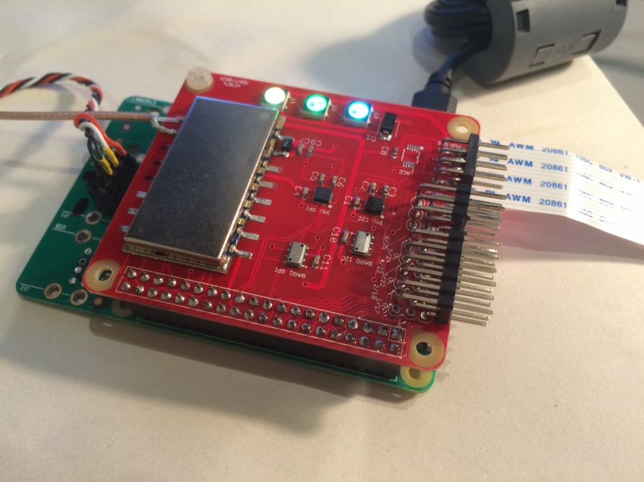
So this is the board almost complete, except for the ADS1115 ADC that didn’t arrive still:

final pcb


The last few days I spent trying to get the RF4463 chip to respond on SPI1. I expected surprises and I got them:

  • first of all, activating SPI1 on a RPI3B results in boot times of 2 minutes due to an interrupt issue with the UART driver. Solution: disable the bluetooth and use ttyAMA0 instead of ttyS0
  • next I simply couldn’t get the chip to respond at all. 2 days I spent on this until I went back to the schematic thinking the wiring is not ok. Then I realized that the chip select is connected to CS2 which is GPIO 16 but the SPI1 overlay I used uses GPIO 18 as CS. Duh! Solved by adding
  • that’s it – it works now:)


In the last moment I added 3 WS2812B RGB LEDs thinking that I will be able to drive them with PIGPIO. I didn’t check the datasheet closely enough to see that they need PWM impulses in the order of 0.5ns whichare way below the resolution of the library.

So today after soldering the LEDs I realized that I cannot drive them. Desperate, I turned to the schematic and saw that by sheer luck I connected the LEDs to GPIO 13 – which happens to be the hardware PWM channel 1. Yaay – exactly what this library needs.

So I downloaded the lib, configured it on DMA channel 4 and PWM channel 1 and ran it and voila! It works with <1% CPU usage:

final pcb2


So now I have almost all the hardware working – the dual IMUs, the Baros, the RF chip and most importantly – vital for a 2016 multirotor – the LEDs.


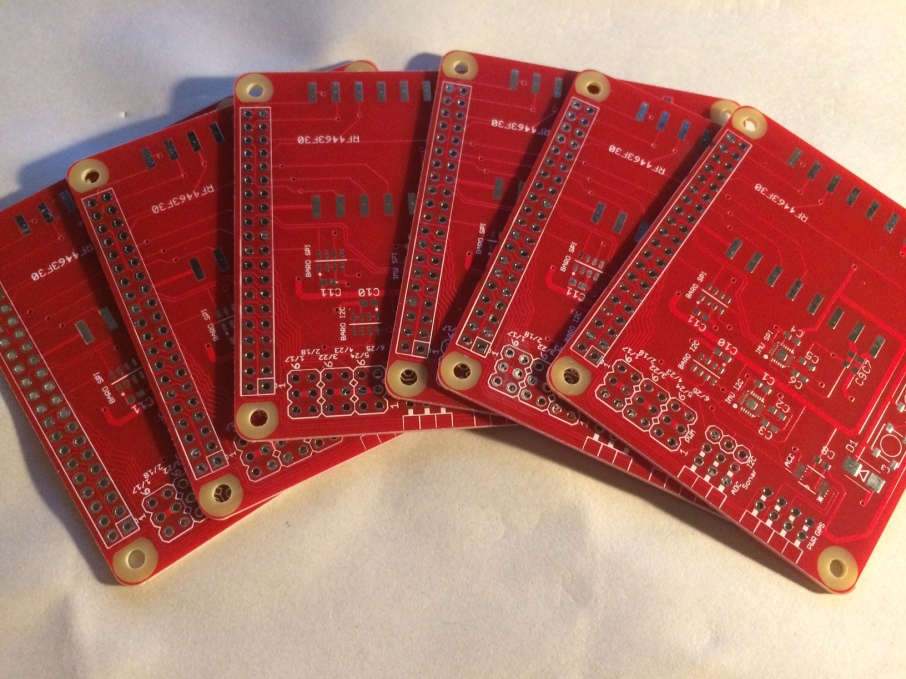
I have 6 unpopulated left to give away (for free of course, shipping covered by you) if someone is interested!

boards


So now – back to software. The RC is coming along nicely.

Read more…