To ensure your flight safety, it is neccessary to check your drone before every flight. Here is a detailed checklist, take a time, and follow the guide to check your drone now !
eftdrone (1)
Benewake Unveils the NOVA20 Solid-State Near-Field Linear LiDAR: Eliminating Robotic Close-Proximity Perception Blind Spots with a 20-Point Array
Recently, Benewake officially launched the NOVA20, a solid-state near-field linear LiDAR designed specifically for embodied AI and mobile robots. Featuring 20 detection channels that form a 40° fan-shaped field of view, the NOVA20 covers the close-proximity zone from 5 centimeters to 1 meter in front of the robot. Working in tandem with 360° rotating LiDARs responsible for long-range scanning, it provides robots with a low-power, glare-resistant, and flexible near-field safety perception solution that can be distributed along the robot's body.

▲ Benewake NOVA20 solid-state near-field linear LiDAR (right), comparable in size to a beer bottle cap
Adopting a pure solid-state design with no moving parts, the NOVA20 is roughly the size of a beer bottle cap (25 × 22 × 13 mm typical), weighs less than 5 grams, consumes an average power of under 1 watt, and operates reliably under 100 Klux of intense ambient light.
The Dilemma of Embodied Robots: "Seeing the Distance, Missing the Meter"
As embodied AI accelerates toward commercial deployment, a fundamental issue has become increasingly prominent: the "close-range safety zone" within 1 meter in front of the robot remains a blind spot in existing sensing setups. While 360° rotating LiDARs handle long-range scanning, they leave a blind zone right next to the robot. Meanwhile, head-mounted cameras suffer from a short-range blind lower limit and are easily occluded by the robot's own limbs. Traditional solutions also fall short: ultrasonic and infrared proximity switches offer too few measurement points with large blind spots; triangulation-based linear lasers fail completely under outdoor bright light; and common 3D array solutions struggle with high-reflectivity crosstalk, bulkiness, and high costs.

▲ Stair edges, side obstacles, and other close-range hazards often fall outside the field of view of primary head-mounted cameras
This is not a niche problem. According to IDC data, global shipments of humanoid robots reached 18,000 units in 2025, and TrendForce projects global shipments to exceed 50,000 units in 2026. As robots enter real-world environments such as factories and commercial facilities at scale, physical guardrails and safety supervisors cannot always be present. Promptly detecting people and obstacles and slowing down or stopping before physical contact becomes an essential capability.
Furthermore, safety should not rely solely on high-level models prone to misinterpretation. Even the most advanced end-to-end models cannot deduce spaces occluded by the robot's own body. Continuously offloading high-frequency judgments—such as whether there is an object nearby and how far it is—to models drains the robot's limited computing power, battery, and thermal space. The industry urgently needs a deterministic ranging bypass independent of high-level models that can be independently verified: models handle understanding and planning, while underlying control systems rely on this data to slow down, detour, or stop. The updated ISO 10218 series of industrial robot safety standards (2025 edition) has incorporated collaborative safety capabilities such as "Speed and Separation Monitoring (SSM)", and the upcoming ISO 25785-1 standard for dynamically stable mobile robots is also under development—using deterministic ranging to guard human-robot separation is becoming a clear industry direction.
Designed precisely to bridge this gap, the NOVA20 integrates solid-state device architecture and array design into a systematic near-field safety solution, combining five major characteristics into a single LiDAR: pure solid-state architecture, linear array detection, compact size, high cost-effectiveness, and outdoor usability.

▲ 360° rotating LiDAR looks far, while the NOVA20 clears the blind spots right ahead: long-range and near-field sensors perform their respective duties
Highlight 1: A 20-Point Array Opening a 40° Fan-Shaped Sector, Clearing the Near-Field with a Single Module
The NOVA20 deploys 20 detection channels within a 40° field of view (evenly distributed across ±20°), measuring distances collaboratively at a 10 Hz frame rate with centimeter-level precision. Unlike single-point solutions that only register a sudden change, 20 channels can simultaneously observe distance variations across different directions within a fan-shaped zone. For instance, when a robot approaches the edge of a step, readings in a specific direction suddenly increase, enabling the system to react rapidly and providing more comprehensive near-field data for fall prevention and lateral collision avoidance.
Near-field detection requires not just visibility, but complete visibility. With a 10% target reflectivity and 100 Klux ambient light, the NOVA20 achieves a range of up to 1 meter with a blind zone of less than 5 centimeters. From the far end of its range down to the 5-centimeter close-proximity end, distance data remains continuous—ensuring that as obstacles get closer, readings stay online, allowing robots to "get close while seeing clearly".
Highlight 2: 100 Klux Glare Resistance and Zero Crosstalk, Reliable Under Intense Outdoor Sunlight
While triangulation linear lasers go blind outdoors, the NOVA20 resists up to 100 Klux of ambient light—equivalent to direct midday sunlight. This means the exact same near-field safety solution can scale seamlessly from indoor environments to inspection, logistics, and outdoor operations. When a robot transitions from a warehouse to an open-air loading dock where lighting changes drastically within seconds, the NOVA20 continues outputting reliable data without data confusion caused by lighting shifts.
To solve "crosstalk"—a long-standing industry headache in array LiDARs where a high-intensity echo "bleeds" into adjacent channels and mixes with real scenarios—the NOVA20 adopts a time-division multiplexing, sequential readout design. This ensures that each echo falls exclusively into its designated channel, translating real environments into clear, distinct points. By eliminating false signals, robots avoid emergency stops or detours caused by non-existent obstacles, making zero-margin edge-following operations far more reliable.
Highlight 3: Beer Bottle Cap Size, Under 5 Grams, Under 1 Watt—Distributed Along the Body and Deployed On Demand
Adopting a pure solid-state architecture with no moving parts, the NOVA20 measures only 25 × 22 × 13 mm (typical), comparable in size to a beer bottle cap. Weighing less than 5 grams (lighter than a standard one-yuan coin) and consuming an average power of less than 1 watt, it is small enough to mount directly onto robot bodies, robotic arms, and limbs for close-range anti-collision protection. Low power consumption also means multi-point deployment adds no extra thermal or stability burden to the system, ensuring long life and outdoor durability.
The NOVA20 does not output images; instead, it provides direct distance data to the underlying control system. This shortens the data pipeline, lowers latency, and preserves precious computing power for semantic understanding, task planning, and fine manipulation—much like how a human doesn't need to recognize a table's category and shape every time they check how far their hand is from a table corner. It acts like a circle of non-contact neural endings outside the robot's "skin," detecting distance changes before physical impact occurs rather than sensing force after a collision.
This design clearly defines product boundaries: the NOVA20 does not replace vision and models, nor does it handle fine force control post-contact; instead, it provides a low-burden, task-specific distance input stream. Paired with a UART interface and ROS/Linux/Windows support, original equipment manufacturers (OEMs) can flexibly deploy sensors based on risk points—covering critical locations first and expanding points according to robot morphology and application scenarios. With its compact size, low power, zero compute overhead, and controllable cost, the NOVA20 integrates directly into mass-production robot BOMs to support large-scale batch deployment.
A Single LiDAR Resolving Three Major Near-Field Challenges for Robots
Focusing on the most typical near-field risks for robots, the NOVA20 underpins three core capabilities: edge-following, fall prevention, and collision avoidance.
Edge-Following: When maintaining a centimeter-level distance from a wall, the robot stays close, moves straight, and avoids scraping.
Fall Prevention: Beams constantly scan the ground ahead, combining 20 points into an area scan to detect slopes and drop-offs in advance rather than waiting for single-point ranging to catch a sudden change.
Collision Avoidance: Beams target obstacles ahead, triggering alerts and stops upon approach to protect the system before physical contact occurs.

▲ Edge-following, fall prevention, and collision avoidance: Three core near-field safety capabilities supported by the NOVA20
Regarding installation, the NOVA20 follows an "on-demand deployment" design: humanoids on the chest, wrists, and ankles; quadrupeds on the jaw and feet; mobile chassis at the four corners—mounted wherever blind spots exist to piece together a localized safety perimeter without stacking bulky, expensive sensors all over the body. The blind spots of embodied AI are precisely where the NOVA20 was born to serve.

▲ Chest, wrists, ankles, and chassis corners—mount wherever blind spots exist
(Specific mounting locations, detection performance, and control strategies should be verified against specific robot structures and actual environments)
Key Parameters

About Benewake
Founded in 2015, Benewake is a LiDAR enterprise dedicated to AI perception for robots and the physical world. Grounded in full-stack technical capabilities spanning "optics, mechanics, electronics, software, algorithms, and chips," the company builds a full-scenario "Eyes of the Robot" product matrix, striving to create perception infrastructure for the physical intelligence era.
Solid-state LiDAR represents Benewake's core technical accumulation: from the first-generation solid-state flash LiDAR CE30 in 2017, to the solid-state small-angle linear LiDAR NOVA in 2024, and now the newly released pure solid-state near-field linear LiDAR NOVA20, nine years of continuous evolution across three generations have established a secure and reliable perception foundation for physical intelligence.
SHANGHAI — At the 2026 World Artificial Intelligence Conference (WAIC), almost every embodied AI robot showcasing its operational capabilities performed inside a guarded enclosure. Nearby safety personnel kept their eyes fixated on three specific areas: near the feet, around the hips, and along the arm movement trajectories.
These spots share a common physical blind spot: they all fall outside the field of view (FOV) of the head-mounted primary cameras, obscured by the robot's own body.
This blind spot is not a flaw in artificial intelligence models. Even the most advanced end-to-end vision-language-action (VLA) models cannot infer unobservable, occluded spaces—it is a matter of fundamental geometry. Yet, for robots to safely navigate human-centric environments, they must first master this critical distance of 5 centimeters to 1 meter—detecting floor drops before stepping forward or sensing nearby people when turning around.
The Divergence in Safety Architecture
Industry leaders like Tesla and Figure rely heavily on vision, multimodal models, and end-to-end learning at the core of their control systems, attempting to connect all sensors and actuators via a unified neural network. While this approach excels at high-level scene understanding and generalization, it struggles with two fundamental issues: physical body occlusions and the heavy compute overhead required for high-frequency, low-semantics proximity checks.
This challenge has shifted the industry toward a functional division of labor. While AI models handle perception and task planning, a dedicated ranging channel guards the safety baseline at close quarters, enabling lower-level control systems to slow down, detour, or stop instantly. This independent pipeline delivers shorter response latency and predictable failure modes—vital requirements for commercial mass production and customer acceptance testing.
Transitioning from AI Models to System Engineering
Robot safety is transitioning from a model capability issue into a full-scale system engineering challenge. According to market research firm IDC, global shipments of humanoid robots surpassed 18,000 units in 2025, with TrendForce projecting that figure to top 50,000 units in 2026. As robots enter factories and commercial facilities, external physical barriers and safety supervisors will no longer be practical.
Updated international standards, such as ISO 10218 (2025) for industrial robots and the developing ISO/CD 25785-1 for dynamic mobile robots, explicitly require strict risk assessment, safety integration, and speed and separation monitoring.
However, onboard computing power, battery capacity, and thermal space remain strictly limited. Offloading basic proximity detection entirely to heavy vision models drains power, increases latency, and inflates hardware costs.
To address this gap, LiDAR developer Benewake has launched the NOVA 20, a solid-state near-field LiDAR module designed specifically for the 5 cm to 1 m range. As Dr. Yuan Li, Founder and CEO of Benewake, highlighted in a public interview:
"As the first unit among perception, prediction, and planning-and-control, LiDAR allows us to see the bigger picture from smaller details during the perception phase."

Consuming under 1 watt, weighing less than 5 grams, and measuring just 25 mm × 22 mm × 13 mm, the NOVA 20 acts as a non-contact tactile layer distributed across wrists, torsos, knees, or ankles.

Solving the Five Proximity Challenges
The NOVA 20 addresses five primary engineering pain points in mass-production robotics:

- Complete Coverage: Featuring a 40° FOV across 20 channel detectors, it monitors a fan-shaped zone with centimeter-level precision to prevent falls and lateral collisions.
- Deterministic Control: By outputting raw distance data directly rather than heavy image streams, it reduces latency and mitigates multi-device cross-talk.
- Compute Offloading: Low power consumption and minimal payload requirements free up primary computing resources for semantic reasoning and manipulation.
- All-Weather Adaptability: Capable of operating under 100 Klux ambient light (equivalent to direct sunlight) with a blind zone under 5 cm, it enables seamless indoor-to-outdoor transitions.
- Bill of Materials (BOM) Integration: Utilizing a standard UART interface, it allows manufacturers to cost-effectively deploy sensors across critical risk points during mass production.

Redundancy Over Singular Perception
The debate between pure-vision setups and multi-sensor fusion is reaching a consensus. Future robotic safety architectures will rely on hardware redundancy across multiple sensor types and control tiers. Large models will govern high-level understanding and task execution, while dedicated physical sensors defend safety baselines at the lowest level.

Reflecting on the relationship between intelligence and perception, Dr. Li noted:
"The emergence and growth of strong intelligence will inevitably require strong perception, but 'strong' never means farther, larger, or more complex. For the robotics industry, true strong perception means reliably getting safety right at the exact distance where it is needed most—using hardware that is small, energy-efficient, and affordable enough."

BEIJING, China — Benewake has officially launched the NOVA20, a next-generation solid-state multi-point LiDAR designed for robotic platforms. As robots move from controlled environments into increasingly complex real-world applications, reliable close-range perception, obstacle avoidance, and human-robot safety have become critical requirements. NOVA20 focuses on the one-meter space around robots, providing direct physical distance sensing to address near-field perception challenges in existing robotic sensor architectures.
The Challenges of Near-Field Robot Perception
Current robotic perception systems face limitations in close -range scenarios:
- Blind Zones of 360° Spinning LiDAR:While conventional 360° spinning LiDARs excel at long-range mapping and global localization, their sensing coverage can be limited within tens of centimeters around the robot, leaving a gap in near-field safety perception.
- Occlusion and Lighting Limits in Vision:Cameras mounted on the head or torso can be occluded by the robot’s own chassis or articulating limbs. Furthermore, vision-based perception can be affected by challenging lighting conditions and requires compute-intensive processing.
- Coarse Resolution of Legacy Sensors:Ultrasonic and single-point infrared sensors offer limited measurement points, making it difficult to reliably resolve low-profile obstacles or sharp drop-offs.
How NOVA20 Addresses These Limitations
NOVA20 is designed to overcome these challenges through a compact solid-state sensing architecture.
- The sensor features a 20-point detection array with a 40° field of view, enabling multi-point distance sensing across a detection range of 0.05-1m (1m @ 10% reflectivity under 100 klux ambient light).
- Weighing less than 5g and consuming less than 1W of power, NOVA20 adopts a compact design with no mechanical moving components, enabling flexible deployment across different parts of robotic platforms, including the chassis, body, wrist, waist, knee, and ankle areas.
- NOVA20 supports operation under strong ambient light conditions up to 100 Klux and directly outputs physical distance information without generating 2D images, reducing unnecessary image data collection and host-level vision processing requirements.
By providing an independent near-field sensing layer, NOVA20 complements existing LiDAR and vision systems to improve robotic safety perception.
Primary Applications of NOVA20
- Lateral Edge-Following and Narrow Passages:Provides multi-point lateral distance measurements for AMRs, commercial cleaning robots, and robotic mowers, supporting more precise wall-following and reducing the risk of side collisions in narrow environments.
- Ground Edge Recognition and Anti-Drop:Detects negative obstacles, staircase edges, and sudden elevation drops for bipedal humanoids, quadrupeds, and wheeled platforms, helping reduce the risk of step-off accidents.
- Human-Robot Proximity and Pre-Contact Deceleration:Provides near-field distance measurements for delivery robots, patrol robots, and collaborative robotic platforms, supporting deterministic speed reduction before physical contact.
About Benewake
Founded in 2015, Benewake specializes in LiDAR technology and physical-world AI perception. The company has delivered more than 3 million units across over 90 countries, supporting developers and manufacturers in building safer robotic systems.
Organizations interested in technical integration, evaluation opportunities, or robotic platform collaboration can visit Benewake’s official website for more information.
Media Contact
Benewake (Beijing) Co., Ltd.
Email: bw@benewake.com
Website: https://en.benewake.com/
Step by Step Assembly Guide: Freewing F 35C 110 mm EDF Jet (PNP Gyro Version, Item FJ50111PG)
Freewing F-35C 110mm EDF jet manual(2026 new)
Freewing F-22 Raptor v2 90mm edf jet manual(2026 new)
This build follows the official factory workflow, optimized for the 1/9.6 scale 110 mm F 35C with QUICK II tool free quick release wings, pre installed servos, 6 axis EG01 gyro, sequenced electric retract landing gear, LED navigation/afterburner lights, and a factory mounted 110 mm in runner EDF + 130 A HV ESC (12S power).
Air Force
Pre note: Most electronics (EDF, ESC, gyro, landing gear servos, LED wiring, fuselage servos) are pre installed in factory. Only airframe assembly, wiring plug ins, radio binding, battery fitting, control linkage tuning and CG setup are required.
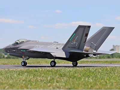
Freewing F-35C Lightning II Super Scale 110mm EDF Jet
Discover more
Drones & RC Aircraft
RC Electronics
Shipping Services

Freewing K-8 Karakorum 80mm EDF PNP Jet
Tools you need
Phillips head screwdriver (1.5 mm 3 mm) Tape (to protect EPO foam from scratches) Zip ties (for cable management) Double sided hook and loop tape (battery mounting) Digital scale + balancing stand (for CG check) 12S Li Po battery (6 000�C8 000 mAh, 60C�C100C discharge rating)
Electricity
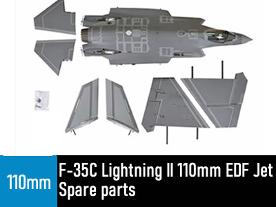
Freewing F-35C Lightning II 110mm EDF Jet Spare parts
All Spare Parts are available in stock.
1. Send email to us,our e-mail is sales@freewing-model.com
we will reply message within 24 hours.
2.Live Chat Online in the following,
Discover more
Physics
Defense Industry
Boats & Watercraft
This Product is available in stock,we will ship the package box within 48 hours after the buyers pay money via paypal.
Spare parts For Freewing F-35C Lightning II 110mm EDF Jet Spare parts
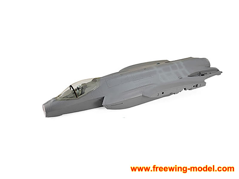
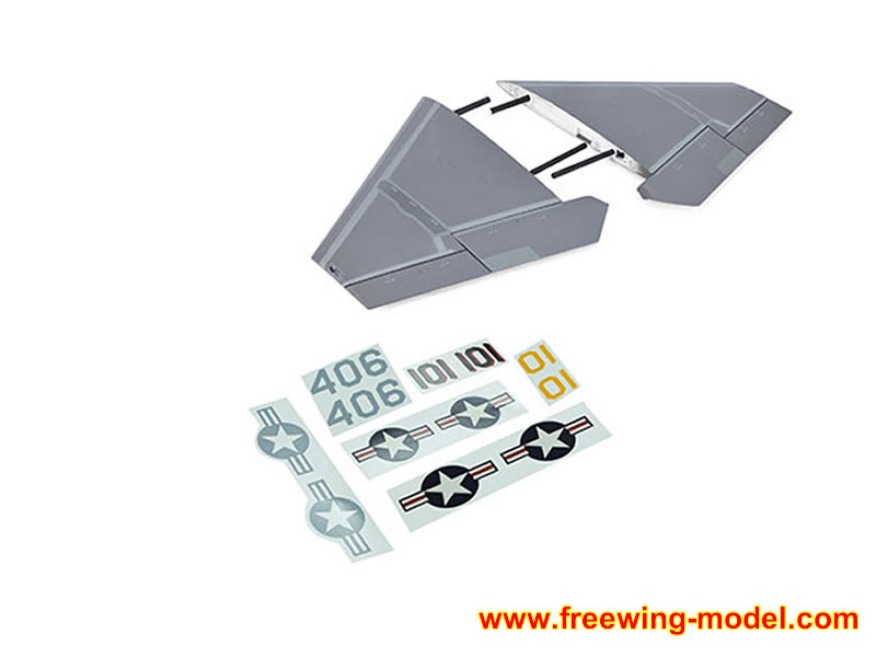
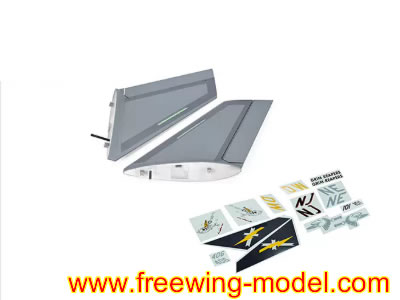
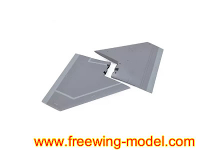
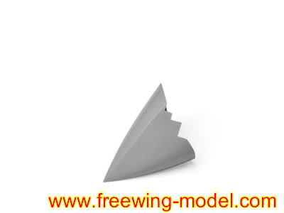
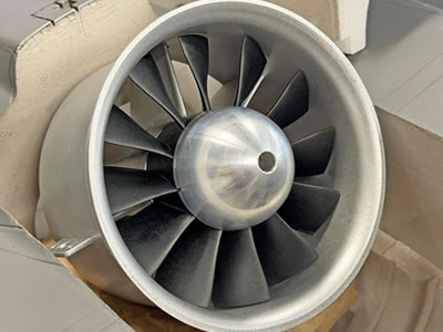
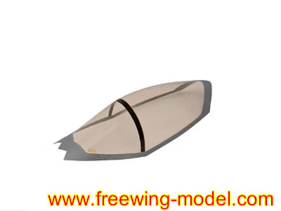
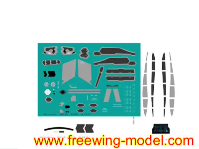
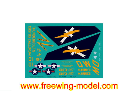
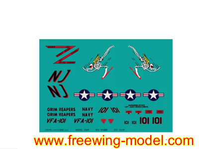
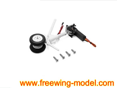
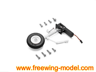
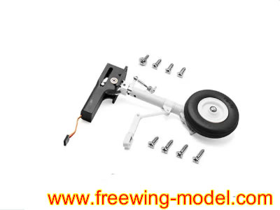
All Spare Parts are available in stock.
Radio Control & Modeling
Discover more
Model Rockets
Radio Control Drones
Propeller Airplanes
1. Send email to us,our e-mail is sales@freewing-model.com
we will reply message within 24 hours.
2.Live Chat Online in the following,
Stage 1: Horizontal stabilizer (Elevator) installation (tail first)
- Align the plastic adapter lugs on each left/right horizontal stabilizer into the pivot slots on the rear fuselage tail boom.
- Plug the elevator servo extension wire from each horizontal tail into the matching fuselage servo plug.
- Center the elevator surface perfectly, then secure the two side horizontal tail mounts with FA3��8 mm machine screws (4 total). Do not over tighten; over torque will strip EPO foam threads.
- Check free elevator travel: full up/down motion without binding or cable snagging. Secure loose wiring with zip ties inside the fuselage tail cavity.
Stage 2: Twin canted vertical stabilizers (Rudders) assembly
- Route vertical tail servo wires through the fuselage vertical fin mounting holes. Connect each rudder servo plug to the fuselage extension harness one by one.
- Seat each canted vertical fin fully down onto the fuselage rear mounting bosses.
- Fasten using 4�� FA3��8 mm screws to lock the vertical stabilizers in position.
- Manually test rudder left right movement; confirm wiring is not pinched between stabilizer and fuselage frame.
Stage 3: Main wing installation (QUICK II tool free plug and lock system, signature for this 110 mm F 35C)
This model uses a carbon fiber main spar plus push button quick lock latches (no wing mount screws required for field assembly):
Aviation Industry
- Slide the thick main carbon fiber spar fully through the fuselage wing root tunnel, spanning left to right wing sockets.
- Unlock the wing latch buttons on both fuselage sides (press the button down to release the lock mechanism).
- Plug the aileron flap servo plugs from each main wing into the corresponding fuselage harness connectors. Double check polarity (pin alignment) to avoid reversed servo operation.
- Slide left right main wing wing root lugs onto the carbon spar, push the wings flush against the fuselage shoulder.
- Release the latch buttons. The spring loaded latches will pop up and mechanically lock the wings firmly onto the airframe. Gently tug each wing to confirm zero play.
For long term static display: Optional set screws can be tightened for extra wing rigidity; leave loose for easy transport disassembly.
Stage 4: Nose section, cockpit canopy and intake duct fit up
- Fit the plastic cockpit tub/pilot detail piece into the forward fuselage cockpit cavity.
- Clip the clear canopy hatch onto the fuselage nose cockpit hinge points; confirm the canopy latches shut securely.
- Install the nose cone; ensure the intake air duct channel inside the nose perfectly aligns with the front inlet leading to the 110 mm EDF unit. Any gaps will reduce EDF thrust performance. Seal minor intake gaps with thin foam tape if there is air leakage.
Stage 5: Landing gear & sequenced gear door pre check (factory pre mounted electric retracts)
All landing gear servos, shock absorber struts, gear door servos and sequencing wiring are pre installed:
- Connect the landing gear harness plug to the main gyro/central electronics board inside the fuselage.
- Power the system on (via temporary battery) and cycle landing gear up/down on your radio transmitter.
- Verify the gear doors open first, struts extend, then doors close (scale sequenced operation). Adjust servo linkage set screws if doors bind, stay ajar or jam.
- Check nose gear steering movement matches your transmitter rudder input.
Stage 6: LED & afterburner light wiring connection
- Locate the navigation light plug (wing/fuselage formation lights) and afterburner LED plug (exhaust nozzle) inside the rear fuselage.
- Plug both into the dedicated LED port on the Freewing EG01 6 axis gyro unit.
- Test: Navigation lights turn on when the radio system powers up; the afterburner LED illuminates under high throttle input (factory pre programmed).
Stage 7: Radio system wiring, gyro setup and transmitter binding
- Plug these components into the EG01 gyro input ports:
- ESC signal wire
- Aileron, elevator, rudder servo main harness lead
- Landing gear servo harness
- LED lighting harness
- Bind your 2.4 GHz receiver to your radio transmitter, then plug the receiver into the gyro��s receiver input port.
- Gyro baseline setup (critical for this large jet):
- Place the jet on a perfectly flat, level surface, keep the aircraft stationary.
- Power on the radio first, then plug in the 12S flight battery to power the jet.
- Hold the trim sliders neutral while the gyro auto calibrates (LED flashes solid once calibration finishes).
- Set gyro gain on your transmitter (start at 50 60% for maiden flight; increase for smoother high speed flight, reduce if the jet oscillates/wobbles).
Freewing F-35C Lightning II Super Scale 110mm EDF PNP Jet
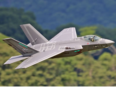
Freewing F-35C Lightning II 12S 110mm ARF Plus jet
Stage 8: Battery installation & Center of Gravity (CG) tuning (most critical flight step)
- Open the top fuselage battery hatch behind the cockpit. Secure the 12S Li Po battery using hook and loop tape on the battery tray.
- Official CG datum for the Freewing 110 mm F 35C: 110�C115 mm back from the leading edge of the main wing root (fuselage wing shoulder).
- Move the battery forward if the nose pitches up (tail heavy, unstable).
- Shift the battery rearward if the nose dives sharply (nose heavy, sluggish turns).
- Once CG is correct, secure excess battery power wiring with zip ties to prevent loose wires from hitting the 110 mm EDF fan.
Stage 9: Final pre flight control surface check
- Double check all control surface directions:
- Aileron: Right stick right next right aileron dips down
- Elevator: Right stick back next elevator deflects upward
- Rudder: Left stick left next vertical tail rudder moves left
- Reverse servo direction in your radio menu if any surface moves backwards.
- Cycle landing gear, test flaps, check all wiring is clear of moving parts and the EDF inlet/exhaust.
- Inspect the 110 mm EDF fan; ensure zero debris inside the fan shroud before the maiden flight.
Quick assembly order recap (field setup version for flying field fast build up)
- Attach horizontal tails . 2. Attach vertical stabilizers . 3. Install carbon spar + lock on main wings next 4. Plug in all servo/LED plugs next 5. Mount battery next 6. CG balance next 7. Gyro recalibrate next 8. Pre flight check next Fly
Freewing K-8 Karakorum 80mm EDF PNP Jet
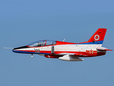
Freewing K-8 Karakorum 70mm EDF PNP Jet
3.Freewing F-35 110mm EDF jet
Air Force
EFT N680: Entry Level DIY Drone Platform
Published: 9, 24, 2026 , | Written by Louis, Technical Department Manager
Programmable drones on the market generally fall into two categories. The first includes block based programming toys that are affordable and well suited for short term, hands on experiences. However, these systems are essentially closed “black boxes.” Once students want to explore the underlying logic behind flight control decisions, they offer limited opportunities for deeper technical learning.
The second category consists of high performance, open source research platforms. While these platforms provide extensive development capabilities, they are often expensive, delivered as bare bone kits, and require a relatively high level of technical knowledge. This creates a steep learning curve for students who are just beginning to explore drone development. coding drone
The EFT N680 is designed to bridge this gap.
As an entry level open source drone development platform, the N680 enables new students to progress from basic hands on training to real flight testing, while giving graduate students and advanced learners a practical platform for algorithm research and academic projects. Its flight control architecture is open at the core, while its modular design allows students to inspect, maintain, and replace individual components themselves.
With comprehensive technical documentation and supporting software, instructors can integrate the N680 into existing courses without having to redesign the entire curriculum.
What Is the EFT N680?
The EFT N680 is a 680 mm wheelbase quadcopter open source drone development platform. Unlike closed educational drones that rely primarily on simplified demonstration applications, the N680 is a professional experimental platform designed to combine stable flight performance with hands on, in depth learning.
Its unified airframe and open source flight control system make it particularly suitable for universities, vocational schools, STEM program leaders, and drone developers. education drone The platform is open and easy to maintain, allowing for repeated use in teaching across academic years.
Design and Configuration
The N680 adopts a fully modular architecture. Its main frame uses a high strength, one piece injection molded nylon structure, combined with carbon fiber arms and landing gear. The fuselage provides ample internal space and reserved mounting points for payloads and peripherals, allowing students to integrate cameras and other equipment for experiments such as aerial imaging and visual navigation.
Featuring a modular design, components such as the arms, motors, ESC/PDB, propellers, snap-fit sealed battery compartment, and flight controller can be replaced independently, facilitating assembly, setup, and maintenance. entry level drone
This modular approach is particularly valuable in classroom environments. If a component is damaged during a test flight, students can replace the affected module instead of replacing the entire aircraft. This helps minimize downtime and keeps practical training on schedule.
A single N680 can support multiple educational experiments covering flight principles, propulsion systems, embedded control, and complete aircraft assembly.
Open Source Flight Control and Development
The aircraft is equipped with the N1 mini open source flight controller, built around a high performance STM32H7 processor.
It features a built in high precision magnetic compass and can be paired with an external GPS compass to provide redundant heading sensing and improve positioning stability.
The flight controller provides a broad range of peripheral interfaces, including 8 motor output channels and 4 servo channels, with reserved expansion buses for CAN, serial, and I2C devices.
The N680 natively supports ArduPilot open source firmware and the MAVLink communication protocol, allowing students and developers to work within a mature open source ecosystem supported by extensive documentation and community resources.
A Progressive Learning Path
The N680 is designed around a progressive learning path.
At the beginner level, students can use ArduPilot to configure and test flight modes, parameters, and waypoint missions. This allows them to understand fundamental drone control concepts through direct interaction with a real aircraft rather than relying solely on simulation or block based programming.
At the advanced level, users can connect an onboard computer and deploy ROS nodes, with access to attitude, position, and velocity control commands. This creates opportunities for projects involving machine vision, autonomous navigation, and other advanced drone applications.
The onboard computer is an optional accessory, while the flight controller includes reserved expansion interfaces for integration.
EFT N1 Assistant Software
The N680 is supported by EFT N1 Assistant, a lightweight parameter tuning application designed to make configuration and debugging more approachable for beginners.
The software provides real time access to attitude data, EKF status, GPS signals, and RC channel data. It also supports flight parameter configuration and log playback, giving students and instructors the ability to review flight data after class.
This makes the same software suitable for both introductory training and more advanced secondary development.
RC Lite Remote Controller
The N680 comes standard with the RC Lite remote controller, featuring an industrial, minimalist design and high precision Hall effect joysticks for smooth and responsive control.
It uses two removable 18650 batteries, supporting direct charging and quick battery replacement.
With 16 output channels, the controller provides the basic channels required for flight control while leaving additional channels available for customized control of expansion payloads such as cameras and deployment devices. This makes the system suitable for a wide range of student innovation and engineering projects.
Flight Performance and Power Characteristics
The N680's flight performance specifications are calibrated by EFT's inhouse R&D team rather than being theoretical figures intended only for product display.
Its power reserves allow the platform to maintain stable and controllable flight while carrying payloads. The airframe can directly accommodate gimbals, thermal imaging modules, and customized sensor kits without requiring structural modifications.
The platform is equipped with a 6S 8000 mAh lithium ion battery, providing approximately 18-27 minutes of flight time under standard operating conditions. Exact performance depends on payload weight and flight mode settings.
The battery supports quick installation and removal. When paired with the included 300 W high power charger, it takes approximately 45 minutes to recharge from empty to full, helping reduce charging downtime during classroom experiments effectively.
Application Scenarios
Drone Beginners
The kit includes the essential hardware required to build the aircraft. Its modular architecture helps reduce the learning curve and allows students to develop a practical understanding of the complete drone system through hands on assembly and training.
DIY Development Enthusiasts
The N680 combines high quality hardware with a proven industrial grade structure, providing a stable and reliable flight platform while giving users the opportunity to learn through assembly, configuration, testing, and debugging.
College Students and Research Developers
Native compatibility with the ArduPilot, MAVLink, and ROS ecosystems makes the N680 suitable for university courses, laboratory experiments, and research projects involving flight control algorithms, machine vision, autonomous navigation, and related technologies.
Industry Innovators
With extensive expansion interfaces and available payload capacity, the N680 can also serve as a practical platform for rapidly validating prototypes for applications such as aerial imaging, surveying, and inspection.
What's Included in the Kit
The N680 is available in three configurations to meet different laboratory and training requirements:
- PNP Kit Includes the N680 frame, 4 E4 motors, 4 30A ESCs, and 4 15 inch folding propellers. This configuration is suitable for laboratories that already have compatible flight controllers and remote control equipment.
- RTF Kit Includes all components of the PNP kit, plus an N1 mini flight controller, GPS module, RC Lite remote controller, EB608 6S 8000 mAh battery, and 300W charger.
- RTF Flight Case Kit Includes everything in the RTF kit, plus an aviation transport case for moving equipment between classrooms and outdoor flight test locations.
All components are also available separately as replacement parts. Importantly, all kits are delivered as unassembled components. Users are required to complete the aircraft assembly and parameter tuning themselves. The EFT N1 Assistant tuning software provides guided tutorials, while the assembly and tuning process itself forms an important part of the handson training experience. beginner friendly drone
Specifications
N680 Drone Platform
Item | Specification |
Wheelbase | 680 mm |
Frame Weight | 2.5 kg |
Maximum Takeoff Weight | 4.7 kg |
Unfolded Dimensions | 867 × 860 × 316 mm |
Propeller Size | 15 inch |
Rotor Count | 4 |
Motor Model | 4214 |
Supply Voltage | 6S |
KV Rating | 380 rpm/V |
ESC Model | 4-6S/30A |
N1mini Flight Controller
Processor | STM32H743 |
Accelerometer & Gyroscope | ICM-42670-P |
Electronic Compass | QMC5883P |
Barometer | SPA06-003 |
Operating Voltage | 5V |
Dimensions | 45 x57.1 mm |
RC Lite Remote Controller
Dimensions | 275.05 x 178.1x 98.65 mm |
Battery | 2 x 18650 Batteries |
Operating Frequency Band | 2.4GHz |
Control Range | 1km |
Charging Port | USB-C |
Weight | 1.5kg |
Battery Runtime | 5-7h |
RF Output Power | 20 dBm |
Operating Temperature | -10°C to 55°C |
External Ports | USB-C, Headphone Jack |
Battery
Specifications | 6S 8000 mAh |
Weight | 1.2kg |
Charger
Input Voltage | 110/220V |
Output Voltage | 1-30VDC |
Charging Current | 16 Ax 2 Channels |
Max. Combined Output | 23 A |
Charging Voltage | 6S |
Weight | 530g |
Frequently Asked Questions
Can I test fly the N680 right out of the box?
No. The N680 cannot be flown immediately after unpacking. The kit includes the required hardware—including the flight controller, GPS, radio link, and power system—but users must complete the aircraft assembly, calibration, and parameter tuning themselves. This process is also an integral part of the practical training experience.
Do I need programming experience to use the N680?
No. The learning path starts with manual flight and simple waypoint missions. EFT N1 Assistant guides users through initial setup and parameter tuning before they progress to ArduPilot configuration and ROS development.
What software and firmware can the N680 run?
The included N1mini flight controller runs ArduPilot opensource firmware and natively supports the MAVLink protocol. ROS algorithm nodes need to be deployed on an external onboard computer. The onboard computer is not included with the kit and must be purchased separately.
Is the N680 suitable as a STEM drone for middle school students?
The N680 is better suited for upper grade middle school STEM courses. It is a laboratory grade development platform rather than a small educational toy. With a 680 mm wheelbase and a 2.5 kg frame weight, it is designed for more advanced practical training in aerospace engineering and drone systems. With the accompanying technical documentation and EFT N1 Assistant software, students can independently complete practical exercises such as aircraft assembly and parameter tuning.
Is the N680 suitable for research as well as teaching?
Yes. The platform can be used for research involving autonomous navigation and sensing technologies. It supports a payload of up to 1 kg and features an open architecture computing module, providing a practical, cost-effective flight platform.However, it is not intended to replace heavy load industrial grade flight platforms.
Can spare parts be purchased separately?
Yes. The arms, motors, ESC boards, propellers, batteries, flight controllers, and GPS modules can all be purchased separately. This allows the platform to remain in service across different student cohorts and academic years.
Which N680 configuration should I choose?
If you wish to select compatible flight controller, remote controller, charging equipment, choose the PNP version. If you want the flight control system and major electronic components included so that the platform can be assembled and configured upon arrival, choose the RTF version. If the drone needs to be transported frequently between classrooms and outdoor flight test locations, the RTF Kit with Flight Case provides a practical transport solution.
If you haven’t found the information you’re looking for, or if you need to review the syllabus, selection recommendations, or bulk purchase quotes, please feel free to contact EFT team.
A camera gimbal gives a drone something very useful: a stabilized view of the world.
But a camera alone does not always answer a simple engineering question:
How far away is the object I'm looking at?
For aerial inspection, surveying, search and rescue, infrastructure monitoring, and other payload applications, the difference between seeing a target and measuring the target can be significant.
One approach is to add a compact laser distance sensor or laser rangefinder directly to the UAV payload. Instead of treating the rangefinder as a separate sensor mounted somewhere on the aircraft, it can be integrated into the same stabilized gimbal as the visible or infrared camera.
This creates a relatively simple concept:
Camera + stabilized gimbal + laser distance sensor = visual identification + direct distance measurement.
The idea sounds straightforward, but getting useful measurements from a moving UAV requires more than simply attaching a sensor next to a camera. Mechanical alignment, optical geometry, vibration, communication, power, and measurement timing all need to be considered.
Here is how I would approach the integration.
1. Why Put the Laser Sensor on the Gimbal?
A common UAV configuration places a downward-facing laser sensor on the aircraft body for altitude measurement.
That is useful for applications such as terrain following, low-altitude flight, and landing assistance.
However, a payload gimbal has a different purpose.
A stabilized gimbal can point toward a specific object while the aircraft continues to move. If the laser distance sensor follows the same line of sight, the system can measure the distance to the object currently being inspected.
For example, imagine an inspection drone looking at:
- a transmission tower
- a bridge structure
- a building facade
- a wind turbine
- a cell tower
- a large tree
- a rock face
- an industrial structure
The camera tells the operator what the object is.
The laser sensor provides the distance to the object.
That combination can be more useful than either sensor operating independently.
2. The Basic Payload Architecture
A simple payload architecture could look like this:
UAV │ ┌───────┴───────┐ │ Flight Control │ └───────┬───────┘ │ Payload Power │ ┌───────▼────────┐ │ 2/3-Axis Gimbal│ │ │ │ Camera LRF │ │ │ │ │ └────┼───────┼────┘ │ │ ▼ ▼ Video Distance Stream DataThe gimbal stabilizes both sensors mechanically.
The camera provides the visual image.
The laser rangefinder measures the distance along its optical axis.
Depending on the application, the measurement data can then be sent to a companion computer, payload controller, telemetry system, or ground station.
The important point is that the rangefinder does not necessarily have to become part of the flight-control loop.
In many inspection applications, it can simply act as an additional measurement channel.
3. The Most Important Mechanical Issue: Optical Alignment
This is probably the first problem I would solve when building such a payload.
The camera and laser sensor do not necessarily need to be physically coaxial, but their optical axes should be known and stable.
Consider a camera and rangefinder mounted a few centimeters apart.
At a short distance, the difference between their viewing directions may be relatively small.
At a long distance, however, even a small angular offset can cause the laser spot to land somewhere different from the center of the camera image.
This becomes important when the operator is trying to measure a small target.
For example, the camera may be aimed at an electrical insulator while the laser is actually measuring the structure behind it.
That produces a perfectly valid distance measurement — but it is the wrong measurement.
A practical approach
During payload assembly, define a reference axis for the camera.
Then align the laser sensor as closely as practical with that axis.
After mechanical installation, perform a calibration procedure at a known distance.
The calibration does not necessarily need to be complicated.
A large flat target can be placed at several known distances. The operator can compare the laser measurement with the center of the camera image and determine whether an angular correction is required.
The important thing is to treat the camera-to-laser offset as a measurable parameter rather than assuming the two sensors are automatically pointing at the same location.
4. Gimbal Movement Changes the Geometry
There is another reason why gimbal integration is interesting.
A fixed sensor mounted directly to the drone has a relatively simple relationship with the aircraft body.
A gimbal does not.
The payload may continuously rotate in pitch, yaw, or both.
Therefore, the laser measurement needs to be interpreted together with the gimbal orientation if the final objective is more than simply obtaining a raw distance value.
For example:
Drone Position │ │ ▼ Gimbal angle │ ▼Laser distance │ ▼Target positionIf the payload controller knows:
- UAV position
- gimbal yaw
- gimbal pitch
- laser distance
- camera orientation
it becomes possible to estimate where the measured point is located relative to the UAV.
This is where a relatively simple distance sensor can become part of a much more useful measurement system.
5. Choosing the Right Laser Technology
Not every laser distance sensor is suitable for a gimbal payload.
This is one area where it is easy to select a sensor based only on its maximum range.
For a UAV gimbal, I would consider at least five parameters:
Measurement range
How far does the sensor actually need to measure?
A sensor designed for 30–100 m applications is very different from one intended for several hundred meters or more.
Do not select a long-range sensor simply because the specification looks impressive. The required range should come from the actual target and flight scenario.
Measurement frequency
A gimbal-mounted sensor does not necessarily need the highest possible measurement frequency.
For a target-distance measurement payload, a stable measurement at a few readings per second may be more useful than extremely high-frequency data.
On the other hand, if the measurement is being used for dynamic control or fast-moving targets, response time becomes much more important.
Accuracy
The required accuracy depends on the application.
For example, measuring the approximate distance to a large building may not require millimeter-level accuracy.
A dimensional inspection application has very different requirements.
Target characteristics
Laser ranging performance can depend strongly on the target.
Dark, reflective, transparent, textured, or highly angled surfaces may behave differently.
A range specification should therefore be evaluated together with the intended target type.
Physical size and weight
This is especially important for small UAVs.
A theoretically excellent sensor may not be practical if it adds too much weight or requires a large optical assembly.
For a gimbal payload, compactness can be just as important as measurement range.
6. Communication: Keep the Payload Interface Simple
The laser sensor does not necessarily need to communicate directly with the flight controller.
A common architecture is:
Laser Sensor │ UART / RS232 / RS485 / USB │ ▼Payload Controller │ ├── Camera ├── Gimbal ├── Telemetry └── Companion ComputerThe exact interface depends on the sensor and payload electronics.
For a small custom payload, UART or TTL serial communication can be convenient because the hardware is simple.
For longer cable runs or electrically noisy environments, RS485 can be attractive because it provides a more robust differential communication link.
The important design principle is to separate measurement acquisition from flight control unless there is a specific reason to connect them.
A payload can first collect reliable distance measurements.
Once that works, the data can be integrated into the broader UAV software architecture.
7. Power and EMI Should Not Be an Afterthought
A laser rangefinder may be a small component, but the payload still has to operate in a fairly electrically noisy environment.
A UAV may contain:
- brushless motors
- ESCs
- high-current power wiring
- video transmitters
- radios
- GPS
- companion computers
- servos or gimbal motors
Poor power distribution or grounding can introduce unexpected communication problems.
For a prototype payload, I would first test the laser sensor independently from the gimbal motors.
Then operate the gimbal while monitoring the distance data.
Finally, test the complete system with motors and other high-current equipment operating.
This staged approach can help identify whether a problem comes from the sensor itself, the serial connection, the gimbal electronics, or the aircraft power system.
8. A Useful Application: Inspection Distance Measurement
One particularly interesting application is infrastructure inspection.
Imagine a drone approaching a tower.
The operator uses the camera to identify a component that needs inspection.
Instead of estimating the distance visually, the operator points the stabilized payload toward the target and activates the rangefinder.
The system returns:
Distance: 126.4 m
The operator can now associate the visual target with a measured distance.
If the UAV and gimbal orientation are also available, the measurement can potentially be converted into a spatial point relative to the aircraft.
This can be useful when documenting inspection data.
The same concept can be applied to:
- bridge inspection
- power-line infrastructure
- wind turbine inspection
- building inspection
- forestry
- geological surveys
- search and rescue
- industrial facilities
The camera remains responsible for visual interpretation, while the laser provides an additional geometric measurement.
9. Search and Rescue Is Another Interesting Use Case
A gimbal-mounted laser rangefinder can also be useful in search-and-rescue payloads.
Suppose a drone identifies a person or object from the air.
The camera provides the visual confirmation.
A directional laser measurement can provide the distance between the UAV and the target.
This can help an operator understand the spatial relationship between the drone and the observed target.
It can also be useful when the payload is looking toward a hillside, cliff, building, or other uneven terrain where simple altitude information from a downward-facing sensor does not describe the distance to the actual target.
This is an important distinction:
Altitude is not the same thing as target distance.
A downward-facing rangefinder measures approximately along the downward direction.
A gimbal-mounted rangefinder measures along the direction in which the payload is pointing.
These are different measurements for different applications.
10. Don't Confuse a Gimbal Rangefinder with a LiDAR Mapping System
It is also worth clarifying the role of a single-point laser rangefinder.
A compact laser distance sensor typically provides a distance measurement along one measurement direction.
A LiDAR mapping system may collect many measurements across a field of view and generate a point cloud.
These are not interchangeable systems.
For example:
Single-point laser rangefinder
Drone \ \ ● TargetOne measurement direction.
Scanning LiDAR
\ | / \ | / ---- UAV ---- / | \ / | \Multiple measurement directions.
If the objective is simply to determine the distance to a selected inspection target, a compact rangefinder may be much simpler than installing a complete 3D scanning payload.
This distinction can help keep the payload lightweight and easier to integrate.
11. What I Would Prototype First
If I were building this payload from scratch, I would not start by integrating everything into the UAV.
I would build the system in four stages.
Stage 1 — Bench test
Connect:
- laser distance sensor
- power supply
- serial interface
- computer
Verify measurement stability and communication.
Stage 2 — Camera alignment
Install the camera and laser sensor on a rigid bracket.
Measure a large target at several distances.
Adjust the optical alignment.
Stage 3 — Gimbal test
Install the bracket on the gimbal.
Move the gimbal through its normal pitch and yaw range.
Verify that vibration and movement do not interrupt the distance measurements.
Stage 4 — Flight test
Only after the payload works reliably on the bench and gimbal should it be installed on the aircraft.
During flight testing, log:
- UAV position
- gimbal orientation
- laser distance
- timestamps
- camera frame or image reference
This data can later be used to evaluate the complete measurement chain.
12. The Bigger Idea: Camera + Distance Is More Useful Than Camera Alone
The interesting part of this integration is not the laser itself.
It is the additional information it provides to an existing camera payload.
A camera answers:
What am I looking at?
A laser distance sensor answers:
How far away is it?
A gimbal answers:
Which direction am I looking?
And the UAV navigation system provides:
Where am I?
Combining these four pieces creates a much more informative payload.
For many UAV projects, this does not require a complicated sensor suite.
A compact laser rangefinder, a stabilized camera, a gimbal controller, and a suitable communication interface can already provide a useful foundation for distance-aware aerial inspection.
Conclusion
Integrating a laser distance sensor into a UAV gimbal is not simply a matter of adding another sensor to a drone.
The real engineering challenge is making the camera, laser, gimbal, and aircraft work as one measurement system.
For a practical build, I would pay particular attention to:
- Optical alignment between the camera and laser
- Gimbal orientation and measurement geometry
- Required measurement range and accuracy
- Sensor weight and physical dimensions
- Communication interface
- Power and EMI
- Timestamping and data synchronization
The result can be a useful transition from a traditional camera payload to a measurement payload.
For UAV builders working on inspection, surveying, SAR, or other directional sensing applications, a compact laser distance sensor can be an interesting addition when the mission requires not only seeing a target, but also knowing its distance.
If anyone here has integrated a laser rangefinder into a 2-axis or 3-axis gimbal, I'd be interested in hearing how you handled camera-to-laser alignment, communication with the payload controller, and measurement synchronization during flight.
Operating agricultural drones across scattered small plots has long been a major headache for professional pilots. Traditional workflows often require frequent takeoffs and landings, leading to massive amounts of wasted transit time, higher battery depletion, and sharply reduced overall efficiency. If you are struggling with fragmented farmland, there is a smarter way to work.
The Solution: EFT Multi-block Work
https://www.youtube.com/shorts/74s3Qppvt3g
By tapping the Multi-block Work feature in the EFT Flight Assistant App, operators can seamlessly link multiple distinct plots into a single automated mission. This eliminates redundant manual interventions, drastically reduces transit downtime, and significantly boosts operational efficiency across complex landscapes.
Step-by-Step Guide to Multi-block Operations
To get started and maximize your spraying efficiency, follow this detailed workflow directly from your app interface:
Plan & Save Blocks: First, map out and save each target plot individually within the app boundary settings.
Mark Obstacles: Pay close attention to surrounding barriers or obstacles between plots. Be sure to mark them in advance during the planning stage for safe navigation.
Enable Multi-block Work: Once block editing is complete, toggle on the Multi-block Work option in the block list or on the main map. You can select up to 10 blocks per mission.
Preflight Route & Parameters: Tap preflight to edit flight routes for each block in sequence. Configure block parameters (such as application rate, speed, and height) either individually or uniformly across all selected blocks.
Autonomous Execution: Upload your customized flight routes, slide to start the task, and watch your drone operate automatically. The drone will seamlessly fly to the next block upon finishing the previous one.
Ready to scale up your agricultural efficiency? Follow us for more professional drone training guides and tips: https://www.store.effort-tech.com/
#EFTDrone #flightassistantapp #agriculturaldrone #agriculturalUAV #multiplotoperation #CropProtection #precisionaguav #sprayingdrone #agtech #agdrone #AgriculturalProtection #dronepilot #LowAltitudeEconomy #AerialProtection

For teams relying on a professional survey drone or inspection drones, high-accuracy positioning has become essential. Surveying, infrastructure inspection, mapping, and precision cleaning all demand reliable centimeter-level data. The EFT X950…
Industrial drone operators know the real bottlenecks rarely come from the airframe itself. They appear on the ground—between job sites, when batteries run low, or when a team needs to move quickly from one inspection point to the next. The EFT X950…

Benewake Unveils the NOVA20 Solid-State Near-Field Linear LiDAR: Eliminating Robotic Close-Proximity Perception Blind Spots with a 20-Point ArrayRecently, Benewake officially launched the NOVA20, a solid-state near-field linear LiDAR designed…

SHANGHAI — At the 2026 World Artificial Intelligence Conference (WAIC), almost every embodied AI robot showcasing its operational capabilities performed inside a guarded enclosure. Nearby safety personnel kept their eyes fixated on three specific…
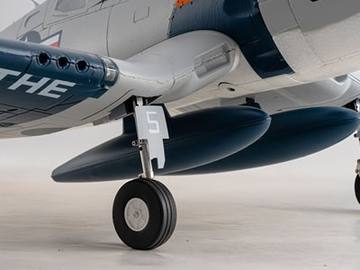
The FMS F4U-4 Corsair with a 1100 mm wingspan combines the distinctive appearance of this legendary warbird with a powerful 4S brushless power system. Its characteristic inverted gull wing, scale four-blade propeller and detailed finish create an…
BEIJING, China — Benewake has officially launched the NOVA20, a next-generation solid-state multi-point LiDAR designed for robotic platforms. As robots move from controlled environments into increasingly complex real-world applications, reliable…
BEIJING, China — Benewake has officially launched the NOVA20, a next-generation solid-state multi-point LiDAR designed for robotic platforms. As robots move from controlled environments into increasingly complex real-world applications, reliable…
Hi everyone,When designing custom visual setups for amateur multirotors or fixed-wing UAVs—such as planning custom 3D printed TPU/PLA canopies, testing contrasting arm-guard colors, visualizing high-visibility aerial schemes, or previewing custom…
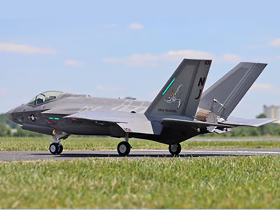
Step by Step Assembly Guide: Freewing F 35C 110 mm EDF Jet (PNP Gyro Version, Item FJ50111PG)Freewing F-35C 110mm EDF jet manual(2026 new)Freewing F-22 Raptor v2 90mm edf jet manual(2026 new)This build follows the official factory workflow,…
"I came across this discussion while looking for information about small hardware parts, and it reminded me how useful it is to have a place where people can share practical sources and recommendations. Finding the right screws, nuts or other small…"
X950 Industrial Drone Platform: Simplified RTK Installation for Precision Field Work
For teams relying on a professional survey drone or inspection drones, high-accuracy positioning has become essential. Surveying, infrastructure inspection, mapping, and precision cleaning all demand reliable centimeter-level data. The EFT X950…
Read more…
0 Replies
Outdoor EFT X950: Portable Power That Eliminates Battery Stress
Industrial drone operators know the real bottlenecks rarely come from the airframe itself. They appear on the ground—between job sites, when batteries run low, or when a team needs to move quickly from one inspection point to the next. The EFT X950…
Read more…Using reference-image transformation to explore custom drone canopies, livery schemes, and 3D print styling
Hi everyone,When designing custom visual setups for amateur multirotors or fixed-wing UAVs—such as planning custom 3D printed TPU/PLA canopies, testing contrasting arm-guard colors, visualizing high-visibility aerial schemes, or previewing custom…
Read more…Smart cleaning drone global market research questionnaire
We're developing intelligent cleaning drones for global markets and we need your input.Cleaning service providers, equipment distributors, O&M operators—share your needs and biggest challenges with us. Take the survey:…
Read more…