All Posts (11086)

Sort by
3D Robotics

This is a very powerful new compute platform for drones, optimized for computer vision. It ships with P4X/Dronecode flight code. (Qualcomm is an investor in 3DR. Now you know why ;-)

Official press release here. Article from Fast Company:

Qualcomm, the world’s leading developer of chips for smartphones, today unveiled a platform for consumer drones that it says can make the flying vehicles lighter and less complex while supporting the camera functionality of the most sophisticated offerings on the market today.

The Qualcomm Snapdragon Flight (which gets its name from Qualcomm’s premium tier Snapdragon 801 processor) is the reference platform developed over the last six months by the San Diego-based chip giant’s research and development lab, and features support for a 4K camera for video, two cameras for depth, and a fourth camera for indoor stabilization, Fast Company has learned.

In short, Qualcomm says it has created the basis for the world’s smallest flying 4K cameras, capable of 1080p video at 60 frames per second, drones that are in their entirety lighter than the gimbals on many existing drones with 4K cameras.

The first known customer is Yuneec, a Chinese rival to drone industry giant DJI.

Qualcomm hopes the Snapdragon Flight will be adopted by both existing drone manufacturers and newcomers to the burgeoning space. Given that a January report from Radiant Insights suggested the global commercial drone market is expected to expand from $609 million in 2014 to $4.8 billion by 2021, Qualcomm is betting its new platform could bring it a substantial amount of business in the coming years.

That seems likely, said one drone industry expert.

"The integration of Qualcomm’s Snapdragon processors in drones will have the same effect that it’s had on mobile devices," said Colin Snow, founder and CEO of Drone Analyst. "Drones will get even sharper image capture and post-processing, improved performance, and better communications. Combining chips will not only improve imaging and imaging options, but will also improve precious battery power as overall weight of the drone drops."

Added Snow, "4G LTE connectivity will benefit drones since they can use that network to transfer images and eventually use it for communicating to a yet-to-be-developed unmanned traffic management system."

All that said, it is notable that the platform isn’t launching with DJI or other industry heavyweights like 3D Robotics, as customers. For Snapdragon Flight to provide a substantial financial windfall to Qualcomm, it will need to be adopted by companies that sell significant numbers of drones.


3D Robotics's IRISPhoto: 3D Robotics

"The interest level has been great from everybody including the big companies and small companies," said Raj Talluri, senior vice president of product management in Qualcomm’s Internet of Things business unit. "We are hoping that all the companies making drones will be interested in this….The goal of our launching the platform is to make it easy for everybody not to have to develop from scratch. It’s a good starting point and then [manufacturers] can differentiate."

Those that do adopt the new platform, Talluri said, should be able to start selling drones based on it by the first half of 2016, and possibly sooner.

Snapdragon Flight will support Sony IMX camera sensors for video, and Omnivision OV7251 sensors for computer vision. All the processing of the data coming in from those cameras is done on the board, said Talluri.

The board has built-in 802.11n and Bluetooth LE communications as well, and will in the "near future" offer support for 4G LTE dongles, a company spokesperson said. All told, the board is 58 millimeters by 40 millimeters and weighs less than 13 grams.

"The vast majority of a drone’s power consumption goes to the motors," Chad Sweet, the director of engineering in Qualcomm Research’s R&D Lab, told Fast Company,"and the size of the motors and the drone are dictated by the payload weight. So when you can shrink the payload size and weight, you can effectively make a smaller drone. And smaller drones are safer and much more consumer friendly."

Further, Sweet said, the Qualcomm approach should significantly simplify the electronics inside drones incorporating Snapdragon Flight. "Many of the popular [drone] platforms have between 10 and 12 [printed circuit boards]," he said. "On a platform such as ours, you would have two PCBs without a mechanical gimbal, and possibly a third PCB with a mechanical gimbal. So it drastically reduces the complexity of the system."

Qualcomm’s drone work came out of research it’s done on using its smartphone chips in robotics. The company has determined that the sensors it embeds on boards in mobile devices are perfect for integrating with one of today’s hottest consumer products.

"The most interesting area of robotics that’s kind of taken off from the market perspective," Sweet said, "are the drones….The main use case is really flying cameras. The camera’s one of the most important features of a smartphone, so as part of Snapdragon, we’ve put a huge effort into developing a high-quality image-processing pipeline."


The new platforms also offers a wider scope for customization. Drone manufacturers can control flights on the application side and determine what kind of processing they want, Sweet said.

"Having this much processing power really opens up the differentiation substantially," he said. "They now have the compute capability to do different things. On many contemporary products, there’s not much compute capability."

Those that do have decent on-board processing power, he said, include 3D Robotics’ Solo, and DJI’s Matrice.

Lastly, the Snapdragon platform also offers support for very-low-latency first-person view that can be done in parallel while recording 4K video, Sweet said. The goal in Qualcomm’s R&D lab has been lag of less than 150 milliseconds, what he called the "video game threshold."

Read more…

We need you! Comments on delivery drone project

Hi all

It has been a while since we firstly presented the benefits of drone deliveries. Since then, we have been busy, really busy working on our prototype.

We got important comments from the community that motivated us to keep working on it. And finally we have something to show!

3689666441?profile=original

We have been working on this technology since late 2013, after much designing, redesign, proof of concepts and a lot of software development, we have reach a functional prototype which we think is the best solution for logistics problems!

It is a hybrid three propellers small UAS capable of long range and heavy payload operations. We hope you appreciate the incredible amount of hours dedicated to reach a final design and build the final pre-production prototype.

Although it may seem science fiction, we can say that deliveries thought drones are becoming real. It is known that Amazon and Google are working on it and that Matternet and Flirtey are making amazing progress (like this). They took the initiative and now DBX Drones is developing the technology that will contribute to make a parcel delivery system by air possible!

This development is intended for parcel deliveries and related companies, but we also want to open it to the consumers market (especially to the open source community) because it is fully modular (you could easily configure your vehicle) and it has a remarkable performance in terms of endurance and payload. See the definition of the product here and all its options!

Who knows which use you may find for it! Would we see peer-to-peer parcel sending in the future? We put the design and control software effort and you put your imagination!

The consumer option would be fully compatible with the Dronecode foundation initiative. See the survey to get more details. 

We are already working on the final production design and need you help to know how interesting is for you, not only as possible owner, but as a citizen that may enjoy the service of drone deliveries!

We have an enormous amount of work still to do, so that we offer the best possible product and find enough funding to launch the production. Anyway, we will show soon some more progress.


We know this is the developer community and your feedback is very valuable. That is why we would appreciate your comments in our progress! Please take our survey!


What do you think? Do you think this technology could make a parcel delivery by drone really possible? Would you take advantage of the great performance of this hybrid vehicle?

We would love to know from you and start a conversation where all of you can participate and contribute to this open source development.


Thank you!


PD: Visit us in dbxdrones.com

Read more…

Pixhawk (and APM) Power Consumption

3689666462?profile=originalFor most people running electric vehicles, it has always been assumed that the motor(s) will always use far more power than the flight controller and associated control systems.

However, for those people running internal combustion engines (or gliders, balloons, etc) for long duration flights the question of power consumption of the flight controller becomes a much more important question.

I spent some time measuring the power requirements of a Pixhawk flight controller and thought I'd share the results with the community.

I cut up a USB cable in order to run it through my multimeter. The same was done for another cable with an XT60 connector. This would allow current readings over both USB and battery power.

Over USB power a standard Pixhawk setup (Pixhawk running APM:Plane 3.3.0, GPS/Compass modules, safety switch, buzzer, 433 MHz telemetry radio) a total of 280mA current is drawn. Breaking this down by component gives the following plot:

3689666521?profile=original

Of note in the above pie chart is the GPS module uses almost 1/5 of the total current requirements. The Pixhawk itself uses the vast majority of the power, as expected (with its comparatively high-powered CPU and many diagnostic LED's).

There was very little difference with the APM:Copter and APMRover2 software running in both armed and disarmed states. All 3 APM branches are consistent with their power usage.

Moving on to the other 2 power supply inputs (Pixhawk power module, ESC into servo rail), it was noticed that the main LED on the Pixhawk is very high powered - on the order of a 1/2 Watt.

In comparing the different power supplies, using total power consumption (Watts) is most appropriate. Note when using USB power the USB port on my PC was measured to be 4.5V rather than the 5V standard.

3689666560?profile=original

The above chart uses a full (GPS, compass, radio, safety switch) setup. The “min” and “max” refer to the power draw with the main LED of the Pixhawk off and on respectively.

The Pixhawk does use more power when connected via battery. I put this down to the various LED’s (and possibly a few IC’s) using more power as they would be operating at a higher voltage (5V clean power vs the 4.5V USB power).

The difference between the power consumption via the Power Module and via the ESC would be likely due to a lower efficiency 5V regulator in the ESC. However, the gap (~0.3W) seems a little wide to account for all of it. Some of it may be due to the way power is routed through the protection diodes in the Pixhawk.

Next is a comparison with the old APM2. The APM2 uses a far less powerful processor (both in terms of power usage and data processing capacity) and has fewer sensors on-board. So it would be expected to use less power:

3689666480?profile=original

The APM2 uses roughly 1/3 as much power as the Pixhawk (not including external components). The APM2 is remarkably efficient with its power usage – a maximum of 0.5W!

Putting this together with the appropriate external components and a standard Lipo battery gives us an expected operational time:

3689666537?profile=original

Once the GPS, radios, etc. are included, the gap between the Pixhawk and APM2 narrows. Using a standard 3-cell 2000 mAH battery gives in excess of 8 hours operating time for a Pixhawk and over 10 hours for the APM2, which allows for some very long-duration flights.

In conclusion, for a standard Pixhawk setup, allow 2 to 2.5W power consumption. If this is an issue, look at disabling the main LED and removing non-essential external components.

If power consumption is truly important, it would be worth going back to an APM2, which only uses 0.5W by itself.

Read more…

3689666606?profile=original

Hello DIY Drones Universe,

Here at our CAD Drones Community we've uploaded our very basic 3D Printable "CAD Quad v1.0" Multirotor Design Project and zip folder downloads. We have downloads of Solidworks 2015 Student Edition Parts, Assembly, and Drawing File that have been converted to .stl and .step files for you CAD users who don't have or use Solidworks. If your looking for the Solidworks Student Edition files for this educational project follow the links below. We want you to use our v1.0 design files to help us fix, change, make use as a teaching tool, and edit your own versions to share.

Videos, LIVE Youtube Sessions, PDFs, Drawing Files, Screenshots, Documentation, Tips, and much more coming soon!

[ Follow this link for the STL & STEP files for this project: http://caddrones.com/downloads.htm?a=&act=view&id=19E7CD2E-0416-47F1-8DD8-A3377EECF7C8 ]

[ Follow this link for the Solidworks Student Edition files for this project: http://caddrones.com/downloads.htm?a=&act=view&id=FDDB908B-B169-49CC-B4DD-55B8EE897653 ]

Have a great Thursday,

Joshua Allen Johnson

qpy0R0xyKKJpe5aTzOPuMc0BZXyi78hOMC_O2-BkVciokGPCistSy5OG1NLzmH8a2VhHg2jkFK7DFdZ9ihBGLr_8pGEo3vBX_QfmQ5uGfvkk9B0w7vd0jB-937kmy1_O=s0-d-e1-ft#%3Ca%20rel%3Dnofollow%20href= VXhcykhjVnLGbTS8kb3nIdW4SiTj0BNHBNLsrCv77a6wHQYOgXrlExIWLpJNH_P39BRtXrX6NhhRiL-_LOt-b3j7sJC9Kt5ZwGOLrE1rMSA_w4YhD7CcUm4hOE-xm-3mxeOyg09UeXSsOvTrtOOGaaHwNxcMcq-cxy71Rc1ckEEcLKVO26knKlOhSO_rG-3uKGN-dPs-KGWK-7w=s0-d-e1-ft#%3Ca%20rel%3Dnofollow%20href= 

Founder & CEO | CAD Drones LLC | Website: www.CADDrones.com

Phone: 612-559-9640 | Email: JoshuaAllenJohnson@gmail.com| LinkedIn: https://www.linkedin.com/in/caddrones

Read more…

FLIR introduce new thermal camera Vue Pro

Source: http://www.flir.eu/suas/content/?id=70728

Introducing FLIR Vue™ Pro

Take drone thermal imaging and data recording to the new heights with Vue Pro

With FLIR Vue™ you get all the thermal imager you need for sUAS operations without having to pay for functionality you'll never use. 

Designed for professional use, FLIR Vue Pro is more than a thermal camera, it is a thermal measurement instrument and data recorder that adds tremendous value to your sUAS operations and services. 

Still with the same industry-leading thermal imaging quality and great value as the best-selling FLIR Vue, the Vue Pro adds full data recording of thermal video and 14-bit still imagery. FLIR Vue Pro also uses FLIR Vue's popular and convenient power-in/video-out connection over a 10-pin mini-USB making integration a snap, and ensuring that you'll have easy access to analog video for downlinking. 

FLIR Vue Pro gives you in-flight control of two camera functions through direct PWM connections, and it's MAVLink compatibility makes it ready for the easy image stitching required for mapping, survey, and precision agriculture applications. Plus, it's compatible with Pix4Dmapper right out of the box 

The convenient mobile app makes pre-flight camera set-up and configuration quick and easy so you won't have to drag a computer out to your flying site just in case you need to change a camera setting. 

Best of all, with MSRPs starting at only $1,999, FLIR Vue Pro is the only thermal imager your drone operations will ever need, and it's affordable for today's commercial sUAS operations. 

FLIR Vue Pro gives you more than thermal images, it gives you thermal data for informed decisions.

On-Board Recording

Vue Pro records 8-bit digital video in MJPEG or H.264 formats and 14-bit still imagery to a removable micro-SD card so you won’t lose any of your data to transmission loss. Imagery is saved to the micro-SD card and can be retrieved either from the card or by plugging the camera into a USB cable, where your computer will see it as a storage device.

MAVLink Integration & Camera Control

In addition to being MAVLink compatible, the same Accessory Port connection gives you access to two camera controls over PWM commands, so you can select color palettes, start and stop recording, or trigger the camera's e-zoom in-flight from your radio controller.

Easy to Configure

Vue Pro comes with a built-in, low-power Bluetooth module, so you can easily configure your camera with our custom iOS or Android apps before you take off. Change color palettes, set your image optimization features, configure your PWM inputs, and start recording all without lugging a computer to the field.

Applications

With the same powerful thermal imaging core used in the most popular cameras in the world, FLIR Vue Pro gives expanded flexibility and performance for a price that makes it perfect for applications like:

  • Search and rescue
  • Precision agriculture
  • Roof inspections
  • Power line inspections
  • Substation inspections
  • Cell tower inspections
  • Security
  • Surveying
  • And anything else you can dream up
Read more…

Composite Rotor Blade: Spar Construction

3689666403?profile=original

As mentioned before, I'm basing my full scale quad design around a 4m rotor diameter. That makes each rotor blade 2 m long. I've decided on a NACA0012 airfoil which is commonly used for full scale helo's. This is a symmetrical airfoil with a glide ratio of about 60:1. I'm planning to build the rotors of composites with E-glass fiberglass cloth, epoxy resin and extruded polystyrene foam core. My budget is a meer trickle so I am selecting lower cost (and lower performance) materials than might be desired if my budget were larger. For example, I might use urethane foam and carbon fiber cloth for the rotors. However, I believe I can meet the needs using these lower performing materials. The symmetrical airfoil will allow me to build all 8 rotor blades essentially the same which should simplify things a bit. I have purchased some 6 oz/yd standard weave fiberglass cloth, and Series 2000 epoxy resin with 2 hour working time hardener from http://www.fiberglast.com/ . I am currently experimenting with the fiberglass layup process as this is a new area for me. The 2 hour cure hardener requires elevated temperatures to cure, so I glued up a small part and put it under a work lamp to cure. (suggested temperature is 120-130 Deg F for 12-14 hours. I guess I put it a bit close to the lamp because it melted a crater into the polystyrene foam. In hindsight, I learned the working temp of the Owens Corning Foamular 150 polystyrene board is 165 F. I exceeded that.

I'm working towards building a small section (12" long) of rotor spar comprised of a foam core, 5/16" diam fiberglass rod leading edge (for impact durability and rotor CG management) wrapped in two layers of 6 oz glass at +- 45 deg to hopefully give it strength against shear as the web of the rotor "beam" formed by the upper and lower skins.

3689666331?profile=original

The chord of the airfoil is 20 cm, and this spar is the front 30% of that chord, or 6 cm.  In my research I've seen this approach (a wrapped leading edge acting as a rotor spar) used for rotor blade construction.  After building this small section, I will test how much bending moment it can withstand before breaking or kinking.

3689666409?profile=original

Read more…

Full Scale Quad

3689666308?profile=original

A few months ago, I read the Wright Brothers biography by David McCullough. It inspired me to create. I have always been interested in flight and have enjoyed RC airplanes in the past. The widespread popularity of the quad-copter has sparked a new interest for me.

I am a mechanical engineer, and work in the process control industry. Part of my job involves understanding the inter-relationships between process variables in order to better design a control strategy for the process. Along those lines, one day I got to thinking about the equations governing flight of a helicopter.

At it's most basic level, lift is produced by transferring momentum to the surrounding air. The lift is proportional to the rate of momentum transfer which is proportional to (p)(A)(v^2) where p is the density of air, A is the area of the rotor disc, and v is the velocity of the air downdraft produced by the rotor. Additionally, I learned that the power required to produce this lift is proportional to (v^3). What this meant to me, is that theoretically, I should be able to build a very low power helicopter if I made the rotor disc large enough. Of course, reality intervenes, as it often does, and practical limitations (such as weight, strength, of rotors) steer us to some reasonable compromise between all of the competing design parameters.

With that said, my goal is to design a full scale, low power, quad copter, and then with any luck, build it, and fly it. One of the drivers for this idea was the prospect of eliminating the complication, and tremendous vibration and fatigue associated with the cyclic pitch control of a "traditional" single rotor helicopter. I want to make something more simple, like the small quads. I believe that simple somehow inherently associates with "reliable". Not always true, but a worthy goal.

The basic parameters of this project are (currently) as follows:
Rotor Diameter = 4 meters
Number of Rotors = 4
Empty Weight = 96 kg
Gross Weight = 200 kg
Rate of Climb = 2.5 m/s

Initially, after finding that the theoretical power required to hover 50 kg with a 4m rotor was around 2.7 HP, I was thinking that I could just put a compact power pod consisting of a small 2 cycle engine, gearbox and rotor at the end of each of the 4 arms, and away I would go. Then I started reading about "why we don't have large quad-copters", and realized the inertia of the large rotor makes control an issue as the individual rotors cannot respond with the quickness that a small plastic propeller can. This lead me to the conclusion that I would have to use variable pitch (collective pitch) control rotors in order to get quick response from the aircraft. That gets messy, and is anything but simple, but since my hope is to one day hop aboard this creation, safety is a significant concern, and without control nothing else much matters. So after concluding I need variable pitch rotors,


I thought some more about the 4 engine design, with the 4 engines located at the rotor hubs. I did a quick estimation of the aircrafts moment of inertia in the various axis (roll, pitch, yaw). NOT PRETTY. If I lost an engine, I would be upside-down, and whirling around in a fraction of a second. No time to cut power to the other engines, just a big airborne tilt-a whirl. YIKES! So that revelation let me to a single engine design. OK, not as radical as the 4 engine design, but certainly more sensible.

Read more…

SOLO Smart Drone lands smartly :)

Warning: I think this voids your warranty. :) We integrated an IR-LOCK sensor with a 3DR SOLO. This project was mostly for fun, so don't read too much into the flight performance shown in the video. We only had one test session, and we didn't tune any parameters. 

You might notice that the flight characteristics are similar to those in Randy's precision landing demonstration (link). We ported his code over to the ardupilot-solo repository for this demo. The repositories used for this test are here and here. Unfortunately, the SOLO does not expose the I2C bus that we typically use to connect the IR-LOCK sensor, so we tapped into the power and data lines (SDA/SCL) used by the compass. (btw, it's pretty cool that 3DR sells a SOLO compass leg) 

3689665884?profile=original

3689665966?profile=original

This video also demonstrates a new landing beacon (MarkOne) that we have developed. Initial details on MarkOne are here: http://bit.ly/MarkOne. Significant improvements have been made to the machine vision performance. Namely, we can operate in bright sunlight over water, cars, etc., without worrying about false detections. 

Recently, the precision landing code was pushed to the ArduCopter master, with the intent of having official support in AC3.4. The relevant developer conversation is here, and the ArduCopter wiki entry is here. As always, many thanks to the AC developers and community!

Read more…

Introducing the Nomad (working title)

The Nomadtl;dr: I'm building an open-source, 3D printable rover.

What is it?

Now that I have something to show, it's time to share something I've been working on and excited about!

The Nomad is a 3D printable rover that's designed to be an open rover platform for exploring electronic and software systems. These include micro-controllers (TinyDuino, Arduino), companion computers (Raspberry Pi, Chip, Onion), sensors (cameras, LIDAR, GPS), actuators, computer vision, autonomous navigation APM:Rover, orthorectified imagery etc. etc.

My aim is that the Nomad should

  • be 3D Printable. Perhaps if there's demand the parts can be mass-produced, but replacement parts should be 3D printable, possibly with degraded performance (e.g. simplified axial systems).
  • use commercial off-the-shelf (COTS) parts as far as possible. You should be able to buy bearings, servos, motors and the like form your local hobby store.
  • use COTS, open electronics like Arduino and Raspberry-PI as far as possible.
  • use and generate Open Source software.

The suspension, steering and drive mechanisms are based on the NASA Mars rovers, implementing a rocker-bogie suspension with individual motorised wheels. It is not a fast-moving rover, and it should be able to handle uncertain environments to a certain degree. I want it to be able to navigate outside environments like farms, beaches and mines, as well as inside environments (with small steps and obstructions).

I've been concentrating on the suspension, steering and drive systems a starting point, and as you can see the details are way more evolved than the payload body.

The Suspension and Steering

Here's the printed and assembled suspension and steering for one side:

One side

This is the result of a lot of design iterations. Saying that, there's still a long way to go with both the form and function, but it's now at a point where I can attach these to a body and do some work on the basic movement micro-controller software.

The steering system uses a standard micro-servo with a Dubro ball link and a bit of bended 0.032" piano wire. Here you can see a prototype:

Ball link prototype

Excluding the wheels, one side of the suspension can be printed in one go:

Single print

The axes for the steering system and rocker are 3D printed and a RC Car bearing is used, but the 3D printed axis shaft is too weak and easily breaks off at the junction. Another design is required, possibly using metal shafts. Here's a prototype:

Prototype axis

The motors are standard Polulu Micro Metal Gearmotors, and the motor shaft fits snugly in the 3D printed wheel:

Wheel

Zortrax M200

As an aside, I want to wax lyrical about the Zortrax M200. This is an awesome printer. The results are consistent and reliable, and my enthusiasm for low-cost 3D printing has been rekindled.

I've printed these templates to figure out the measurements for a snug fit on the bearings and motor shaft:

Templates

and the printer reliably produces the same result.

Next

The parts for building both sides of the suspension have arrived, so I can produce these, but I'm waiting for some electronics. The first iteration will use TinyDuino and a Raspberry-Pi. I'll design a basic body and determine any problems with the suspension and steering, and if all goes well my next post will show a driving rover!

The design files (Rhino) and STLs for printing are available on github under a Creative Commons license if you're curious.

You can follow @calvinrobotics on Twitter for updates.

Read more…

Erle-Spider crowdfunding campaign

3689665735?profile=original

About a month ago we announced Erle-Spider, a drone with legs powered by Ubuntu with the Robot Operating System at its core and support/compatibility with MAVLink and other Dronecode Foundation tools. Over the last weeks we've been working very hard to launch Erle-Spider for an affordable price and today I'm happy to announce it's crowdfunding campaign.

3689665839?profile=original

Erle-Spider is available starting at 399 $ and is based on the Robot Operating System (ROS). ROS packages will be available to connect Erle-Spider with existing MAVLink devices and interfaces. 

3689665777?profile=original

Updated link: Erle-Spider can be supported at https://www.indiegogo.com/projects/erle-spider-the-ubuntu-drone-with-legs/#/story.

Read more…
Moderator

image-1.jpg?width=400

With the tagline "Design Cinematic Shots like a Pro", DJI has released a firmware upgrade with several new features that push them further along in the autonomous flight area.

  • Waypoints
  • Point-of-Interest
    Follow Me (Phantom 3 only)
  • Home Lock
  • Course Lock

Some of these features will of course be familiar to long-time diy-droners... it will be interesting to see DJI's videographer-centric take on these.

More details here... I've got everything downloaded and installed, and will have a report later today.

http://eastbay-rc.blogspot.com/2015/09/intelligent-navigation-interesting.html

Read more…

3689665701?profile=original

Drone.bo conference at Engeneering Society of Bolivia with Electronic Engeneering (SIB) and Electricity College Society of Santa Cruz (CIEE).

Drone.bo tells and shows the OpenHardware techonology at enterprises and comercial use to the businessman about important industrial use at agronomy, petroleum scouting, georeferencing, surveying and professional movie production.

The security and vision about drones technology was more debated in this conference, we are working on this, becuase is very important the drone pilot certification and get more secure and reliable to reduce errors on the industries.

3689665638?profile=original

Read more…

anac.jpg?width=425

The Brazilian Aviation Agency (ANAC) has released the newest iteration of their proposed rules for UAV operation (VANT, in Portuguese), and is requesting public feedback until October 3rd, 2015. The official release is linked at the bottom. Feedback can be sent by e-mail to rpas@anac.gov.br, and a public audience will be held in Brasilia on September 11th.

In a nutshell, ANAC will only allow and regulate Remotely Piloted Aircrafts (RPAs), prohibiting the use of fully autonomous UAVs (with no possibility of pilot control during flight). RPAs will be classified according to weight, with specific requirements for each class:

Class 1 (above 150 kg) - Aircraft must be certified by ANAC, be registered in the Brazilian Aeronautical Registry (RAB), and pilots must have the Aeronautical Medical Certificate (CMA), permit, and license. All flights must be registered.

Class 2 (25-50 kg) - Aircraft need not be certified, but manufacturers must comply with all necessary technical requirements, and have the project approved by the Agency. It should also be registered with the RAB, and pilots must have CMA, license and permits. All flights should also be registered.

Class 3 (less than 25 kg) - If operated up to 400 feet above ground level (approximately 120 meters) and in visual line of sight, the RPA will only require a simple registration (operator and equipment information). CMA will not be required, nor registry of the flights. Pilot license and permits will only be required for those wishing to operate above 400 feet. Operation of RPAs up to 25 kg may only occur at a minimum distance of 30 meters from a person. The distance may be less in the case of consenting persons (those who expressly agree to the operation) and persons involved in the operation. In urban areas and rural settlements, operation should not exceed 200 feet above ground level (approximately 60 meters).

Minimum age - RPA pilots for all three classes must be at least 18 years old.

Insurance - will be required to secure third party damage coverage for all RPAs (all three classes), except for government security and civil defense agencies.

Illegal activities or invasion of privacy - illegal activities or invasion of privacy using RPAs will naturally be dealt with by the relevant law enforcement authorities.

Civil defense and public security - public security and civil defense agencies can operate in any areas, at their own responsibility (or an operator at their service), with due compliance to the proposed rules. These operations do not need to have insurance to cover damages to third parties.

Model aircraft - In the case of model aircraft (which are intended for recreation), there is no need for authorization from ANAC, but they should be subject to the minimum distance of 30 meters from non-consenting people. In the case of consenting people (who expressly agree), this distance need not be observed. Under the proposal, there is no minimum age for model aircraft pilots or compulsory insurance against damage to third parties.

http://www.anac.gov.br/Noticia.aspx?ttCD_CHAVE=1914

Read more…

4Gmetry II

3689665444?profile=original
A new version of 4Gmetry is now available on store: 4Gmetry II (504 € 439€) This is the second version of the original KIT proposed on diydrones blog just five months ago. I want to say a big "thank you" to all our 4Gmetry group members, and to the precious feedbacks of our happy customers. Thank you! 

The new 4Gmetry II includes all the necessary components to connect your drone (or fleet) to the internet via 4G/LTE. But it's not only the ready-to-fly solution for lazies developers who don't want to buy components separately! 4Gmetry II is more than the sum of the parts, it's a powerful companion computer for developers and professionals.

FEATURES:

  • 4Gmetry II features a Samsung Exynos5422 Cortex™-A15 2Ghz and Cortex™-A7 Octa core CPUs which makes it a very interesting solution for inflight image analysis applications or computer vision, for a very interesting flying weight. 

  • 4Gmetry II is built on top of Ubuntu 14.04 LTS and comes with ready to connect it to your favourite VPN (it's literally a flying server!). In this way you don't need expensive M2M SIMs or dynamic IP (but every possibility remains up to you).

  • 4Gmetry II naturally interfaces with H.264 cameras - including the famous C920 - so you can easily stream video to your target server/laptop. The quality will be a compromise of framerate / resolution accordingly to your 4G/LTE carrier performance and quality (in US, Italy, Australia, Germany, France, Canada, UK the 4G quality reported by our customers is mostly good).

  • 4Gmetry II is optimized for and tested on APM 3.2.1 over Pixhawk. However 4Gmetry accepts MAVLink messages from virtually any source.

  • Note for beginners: you CAN install custom software on 4Gmetry, the user is not "locked-out"in any way. Simply connect 4Gmetry to an HDMI monitor with an HDMI cable (not included) to get the Ubuntu GUI at your service.

With 4Gmetry you can control your drone/fleet in real time from an unlimited distance over 4G/LTE Internet; use this at your risk and in respect of the law in your country.

UPDATE: We're extensively testing Coriandola - the Cloud Control Station - to remotely manage and orchestrate a fleet of vehicles giving only high level commands in your browser. The goal is to integrate it in the next version of 4Gmetry  ;)

Read more…

From Zero to Fifty Planes in Twenty-Seven Minutes

3689665980?profile=original
 
Last week, the Advanced Robotic Systems Engineering Laboratory (ARSENL) team at the Naval Postgraduate School, based in Monterey, California, successfully launched and flew 50 aircraft simultaneously.
 
It was nearing 110 degrees Fahrenheit on the runway at Camp Roberts, California as we carted the last rack of planes from the flight technicians’ tables over to the launch site. We had started flight preparations around 8:30 that morning, after arriving an hour earlier to set up shade structures, tables, and generators, and unpack some 68 planes we would prepare for flight that day. Knowing that the planes’ limited battery life would restrict our launch window to less than half an hour, and that we’d previously encountered last-minute sensor calibration problems and WiFi devices that went brain-dead in the heat and sun, we conservatively assumed that we would prepare four planes to fly three. Our goal this time was to fly 50.
 
The Fleet
 
3689666015?profile=original
 
The planes we fly are built from the Ritewing Zephyr II kit. These are EPO foam wings with elevons and room for an electric pusher motor. The plane is outfitted with Hitec digital servos, an O.S. motor driven by a Castle Creations ESC, and dual Thunder Power 5000 mAh LiPo batteries. In this configuration, our expected flight time is approximately 45-50 minutes, meaning that we needed to have all aircraft launched within about 30 minutes to have time to perform cooperative flight and to land safely before battery failsafes started to trigger on the autopilot, forcing an autonomous landing.
 
A custom PCB distributes power to and manages some of the wiring for the Pixhawk, which flies a lightly-modified branch of ArduPlane. To the right of the Pixhawk is an ODroid u3 companion computer (“payload” in our team’s parlance) running a stripped-down version of Ubuntu Linux. Our payload software is built on top of ROS, making it easy to add new functionality incrementally. While the Pixhawk manages keeping the plane airborne, the payload ingests autopilot pose and status, which it broadcasts to other planes and to the ground. It also accepts commands from the ground, which are either passed to the autopilot or used to control execution of a handful of payload-directed path planning algorithms, such as leader-follower, distributed search, and sequenced landing. These algorithms “drive” the plane by sending updated target latitude-longitude-altitudes to the autopilot, effectively moving a carrot in front of the plane.
 

3689666088?profile=original

 
The 900 MHz telemetry radios typically used to communicate with the Pixhawk are only a backup link in our architecture, and a tenuous one with nearly 70 of them powered at once. After observing difficulty establishing telemetry links during previous field tests, we measured signal-to-noise with 50 planes powered on the bench and saw that the default 915-928 MHz band was saturated. Following a suggestion from the DIY Drones community, we decided to split our available 902-928 MHz band into three equal-size sub-bands and place an equal number of planes into each sub-band. We reasoned that, even with the reduction in per-band bandwidth, some 22 to 23 planes (of the 68 prepped for flight) in a sub-band would hold up better than all planes in a single, wider band. This intuition came after observing that at most 50 frequency hopping channels could be supported in a band in the current radio firmware.
 
In any case, at most one plane would actively be controlled over the telemetry link, and only in an emergency. Our primary link with the fleet is an ad hoc 802.11n wireless network that connects each plane’s payload with other planes and our ground control stations. All of our command and status traffic is sent via UDP; as with MAVLink, our messages are designed to minimize statefulness and be tolerant to loss and blind retransmission.
 
Should a plane’s payload have failed or the network conditions become too lossy, one of the ground operators’ software had a button that would reconfigure an attached telemetry radio to the select plane’s sub-band and Net ID, and then open a MAVProxy session to that plane within a few seconds.
 
Preparation
 
3689666129?profile=original
 
It took our diligent crew of flight techs close to four hours to prepare all the planes. Preparations comprise not only putting propellors on motors and making sure that all mechanical and electrical connections are secure, but also running through a set of software preflight checks. These checks have evolved over the past two years from a paper checklist - imagine checking the values of 40-odd autopilot parameters by hand - to a MAVProxy module, and finally to a standalone interface that works in concert with the payload and a central configuration server to perform the preflight process.
 
When a plane is first powered, the payload reaches out to the server and pulls down its mission configuration: autopilot parameters, waypoints, rally points, and geo-fence. The payload verifies that the autopilot matches these files and then sets status flags in a message broadcast back to the ground stations.
 
Meanwhile, the flight tech is busily performing sensor and actuator checks. Our Flight Tech Interface (FTI) software reports similar status lights to those in MAVProxy’s console module. A red “as” light indicates that the airspeed sensor must be calibrated; the flight tech places a bottle over the pitot tube and presses the “Cal Pressure” button in the FTI, and a few seconds later the light changes to green indicating completion. Then the servos and motor are checked. For this, we designed simple test stands that are staked into the ground. The plane is secured in the test stand, and then the flight tech once again sends a command from the FTI to the payload. First, they check the servos: the elevons execute a left roll, right roll, up pitch, down pitch, and return to level. Then, the technician arms the throttle and commands a run-up of the motor, which lasts about two seconds. Finally, a second tech picks the plane up and rotates it manually while the first tech verifies on the screen that the autopilot correctly reports roll and pitch.
 
Once done with the checklist, the flight tech clicks one last button, telling the plane to set a “flight ready” status bit so the plane reports as ready for flight. The plane is then placed in a rack built from two-by-fours and PVC pipe, which is moved 100 feet out to the launch site when full. Each rack carries ten planes.
 
Launch Sequence
 
It was getting close to 1 p.m., and some of the aircraft had been powered for multiple hours. Though the amount of power they consume on the ground is small, it isn’t nothing. It was hot, so we were also worried about electronics starting to fail. From our previous field test experiences, we had begun to suspect that heat was an issue for some onboard components including the wireless network devices, so we were continually edging racks of planes under shade structures to track the sun’s movement.
 
As the last planes were carted out and a few last-minute recalibrations were performed, we prepared our automated launcher for its big test run. We had previously used a bungee launch system. It was simple and reliable, though required a person to sprint after the bungee each time it was released, and pull some 25 pounds of force back to the aluminum rails from which the aircraft launched. Between the number of planes to launch and the heat, we were glad to see the new launcher ready for action.
 
The brainchild of two Masters students at the school, the Automated Multi-Plane Propulsion System (A.M.P.P.S.) comprises a chain wrapped around two cogs spaced eight feet apart, set between two parallel rails from which the aircraft launches. On the leading edge of the launcher is an electric motor that draws an impressive 200 amps when spun up at maximum rate. It is capable of accelerating a plane from rest to roughly 16 meters per second before it leaves the rails. Technically, it can do more, though we ran into problems with shearing launch hooks from the airframe.
 
With a few modifications to the motor controller’s acceleration profile and a redesigned, 3D printed adapter attaching the plane to the launch chain, we were reasonably confident that A.M.P.P.S. would launch all 50 planes successfully. Nonetheless, we kept the old launcher ready with a bungee pre-tensioned just in case of a failure.
 

3689666165?profile=original

 
Timothy Chung, lead faculty for the project, called over the radio, “All right team ARSENL, this is it. Everyone have fun, stay safe. Mission 36... commence.” This was the thirty-sixth mission of the week. Most of those missions had been single-plane checkout flights; every brand-new and newly-repaired plane goes through a short "mechanical checkout flight" before being reintroduced into the fleet. Our only multiple-plane missions during the week had been two ten-plane flights the day before, as practice runs for the 50-plane test. The largest number of planes we had flown previously was 30 in July; we had been increasing our numbers exponentially since our first multi-plane flight with the Zephyr platform last year.
 
Time to hustle. We loaded the first plane onto the launcher, and our launch operator used a variant of the FTI to command final configuration parameters. Since any plane might fail to launch, we needed to tell the plane which “slot” in the flight configuration it would fill (more on this later). She then commanded the throttle to arm, and signaled both the safety pilot - who had selected that aircraft on an RC transmitter - and another operator standing next to the launcher, that the aircraft was ready for launch. The second operator pressed two buttons on a gamepad controller wirelessly connected to the launcher, commanding it to launch the plane. Three safety beeps from the launcher, then a loud whirring as the chain suddenly accelerated, kicking the plane off into the air, and that long-seeming moment before the plane detected launch and started the throttle. The plane took off steeply toward its initial waypoint.
 
As the safety pilot confirmed stable flight, an intern carried the next plane over to the launcher. This time, there was some confusion between operators, and it took about a minute to get the second plane airborne. At a minute per plane, we would be landing the first planes as the final ones were being launched.
 
Fortunately, the next few planes launched quickly, at an average of just over 30 seconds per launch. The tenth plane aloft experienced some flight instabilities and the pilot had to pause the launch sequence so he could take manual control and land that plane. That cost us an extra minute. After that, the team found a good rhythm for the rest of the launch sequence. After the 50th launch, the launch operator - who had been keeping track of launches on paper - paused and asked, “is that all of them?” We all looked at each other, then quickly remembered that we had to launch a fifty-first plane to make up for the one that was landed earlier. It’s amazing how difficult it is to keep track of so many planes.
 
In all, we performed 51 launches, all using A.M.P.P.S., in 27 minutes 39 seconds, at an average of 33 seconds between launches. High-fives and handshakes commenced at the launch site, while operations were just ramping up inside a trailer parked 100 feet away.
 
The Flight
 
Our flight configuration consisted of two “stacks” of 25 planes, with each “slot” in the stack separated 15 meters apart vertically. The two stacks were separated laterally so that the orbits and racetracks of one stack would not overlap with the other. Though we launched in altitude order, we designed the waypoint sequence with special “ingress” and “egress” points where planes could ascend and descend without entering the airspace of other planes. This altitude deconfliction meant that we could execute cooperative behaviors within a single stack in two dimensions, without having to worry about implementing collision avoidance due to separation in the third dimension. The launch operator sent the stack and slot configuration to each plane just prior to launch.
 
3689666204?profile=original
Example of a "stack" forming with 12 planes visible.
 
Each time another five or so planes entered the stack, a single operator sitting in a trailer placed away from the launch site would command them into groups and initiate cooperative behaviors. In fact, there were only two operators in the trailer: one was commanding the fleet as a whole, and the other was monitoring planes’ health.
 
We executed our leader-follower algorithm during this flight, due to its heavy vetting in previous field tests. This algorithm determines a single leader and commands all other planes in the group to follow it directly, while maintaining the altitudes set by the launch operator. The highest altitude plane in the group becomes the leader and enters a prescribed racetrack, while all other planes listen to its broadcast pose and compute following positions.
 
Author’s comment: Watching 24 planes stacked almost perfectly on top of one another, following a common lead plane, is pretty amazing. Each plane broadcasts its pose at roughly 8 Hz, but considering wireless contention and the relative orientation of antennas, follower planes may sometimes receive as little as 1-2 updates per second. The payload software extrapolates positions using the current pose and linear velocities only, so the fact that the stack performed so well under lossy network conditions continues to impress me.


3689666192?profile=original
Visualization in Gazebo using data captured in ROS on each payload. Aircraft  are continuing to join the left stack while the rest of the stack are independently loitering at deconflicted altitudes. Those in the right stack are performing a leader-follower algorithm, with the highest aircraft acting as leader.
 
We had 9 minutes 45 seconds with all 50 planes airborne, performing cooperative behaviors in various groups. Due to our long preflight and launch sequence, batteries were quickly depleting in the air. We had to start bringing down planes.
 
With the safety pilot on standby, focusing on individual planes as quickly as possible, we commanded groups within a stack to execute a sequenced landing. Using this algorithm, planes order their landings according to altitude, lowest first, and each plane in sequence begins an autonomous landing. Our landing has each plane perform a descending loiter to 40 meters above the runway, then break into a glide slope until it finally skids to a halt on the asphalt. Each plane bears 3D printed skids that can easily be replaced when they ablate.
 
Landing 50 planes did not happen not without minor glitches. Because we ran close to the limit of the batteries getting all aircraft aloft and executing cooperative behaviors, a few planes triggered their low-battery failsafe and automatically executed a controlled autonomous landing alongside those performing the sequenced landing. This made for great video, though the safety pilot had to pick one to monitor and one to let land on its own. Scrolling through models on his transmitter took most of his attention, otherwise. A couple planes' ESCs also triggered their own low-voltage failsafe and cut the throttle, causing a controlled descent into a field adjacent to the runway. Thankfully, all but two of these planes had a soft landing, and all batteries were intact after landing - though some were retired due to their low remaining voltages.
 
3689666230?profile=original
Example of sequenced landing showing three aircraft inbound.
 
Planes able to make it to the runway faced another challenge. All planes were programmed with the same landing point, with the assumption that GPS and barometer inaccuracy would provide sufficient spread on landing. But with nearly 50 planes on the runway, on-deck collisions were unavoidable. Some of the video captured by GoPro cameras mounted to the nose of each plane show skidding into other planes, or coming down directly on top of other planes on the ground. Lesson learned for next time: add a bit more variation to the landing coordinates.
 
Conclusion
 
On August 27, 2015, at roughly 1:20 p.m., the ARSENL team achieved a major milestone in our research: we launched and flew 50 planes together, executing cooperative behaviors in flight, operated by only two humans during flight and a total team of 16 people. 
 
3689666051?profile=original
 
The team that performed the flight (from left to right): Randy Bice, Kevin Jones, Marianna Jones, Ray Davis, Tyler Lippert, Michael Day, Evan Maki, Brian Le, Aaron Ray, Bob Been, Paul Epperson, Timothy Chung, Mike Clement, David Harach, Duane Davis, and EJ Montoya. This flight would not have been possible without the contributions of countless additional faculty, staff, students, and interns; ONR reservists; and the ongoing work of the DIY Drones community.
 
Photos courtesy of the ARSENL team and the Naval Postgraduate School Public Affairs Office. Find out more at arsenl.nps.edu.
Read more…

The deadline has now passed for submitting Deliverable 1 documents to the 2016 UAV Challenge Medical Express. We received 64 D1 documents from teams from all over the world. The Technical Committee will now get to work reading through the documents and assessing teams for the Go/No-Go decision. This process is likely to take 2-3 weeks.

54-dsc_3866.jpg?width=450More information can be found on the UAV Challenge website.

Read more…
Moderator

RC Electric Calculator App for Android

33z5z6u.jpg?width=200RC Electric Calculator App for Android - version 3.0 is coming out shortly with many improvements and some calculations specifically for multirotors/copters! (Free update of course if you have already bought v2.x)

It's basically an 8-in-1 calculator for electric powered model airplanes, helicopters, multicopters, cars, trucks and buggy's, if fact anything that uses rechargeable* batteries. (*As long as the voltage is known then any rechargeable battery including LiPo, LiFe, NiCd and NiMh batteries can be used for some calculations). US imperial units and metric units are also catered for!

One of the units used for the calculations in the app is the mAh (mill-amp-hours). All batteries have a mAh or Ah rating, this is the capacity of the battery or how much energy is stored. After you've recharged the battery your digital charger will show you how many mAh has been put back into the pack i.e. how much was used. This number is used to calculate a number of things in the app, like expected flight time using 80% of the pack or the average current used during the flight or run.

A use for this app is to calculate the average current draw of a multicopter in a hover and then from this calculate the expected flight time. (I flew with ArduPlane for 29 minutes from 2300mAh and the app calculated the average current draw as 4.6 Amps, or 1.6C and 77% of the 3000mAh pack!)

Link:

t9DgIgHpFau5703XajBuqs7k1SBYlbNxHDfSU-78HltrcKLuFaBSsA0ps0fo9sA-C2Nu=w124RC E-calc Pro - only $1.99

As from v2.0 all the calculations are made "on-the-fly" so no buttons need to be tapped, just input your values and the calculations will be made when enough data is available.

The images should be self explanatory as to how it all works but feel free to ask any questions.

Zf6MPJeS33KhhOG666HPRkgX1uVYk9A0_r4E83_m5sw2NupwjAHQ_p021ZS4WgQwLKUq?width=200tdQwzW39t7OvZQDG34nsM3vIjDpBoi-IuOdwZX7H9AGksFw_x6mcSyiruDOiSARcFxY?width=200
momoEFvFf1gk8O4WO3kEpicLUunGQ4Wj_Sln3BWwOnUyn0VuaEp1E0pSZzvx3fH4918?width=200gT-EoU929UZQ5nBw4RS8_z9JfOG5dLtyuZ4SiAvpzjOVyWmKLyAxbROu6OwAgu5JfCln?width=200


Use RC E-Calc Pro to calculate the following:
- Average Current Used by the aircraft during a flight/run.
- Average Discharge Rate (C-rate) of the LiPo battery during a flight.
- Expected Flight Time using 100% capacity of a battery.
- Expected Flight Time using 80% capacity of a battery.
- Realistic Flight Time using 80% capacity of a battery and 70% average throttle.
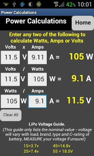
- Power in Watts from Volts & Amps.
- Volts from Power & Amps.
- Current in Amps from Power & Volts.
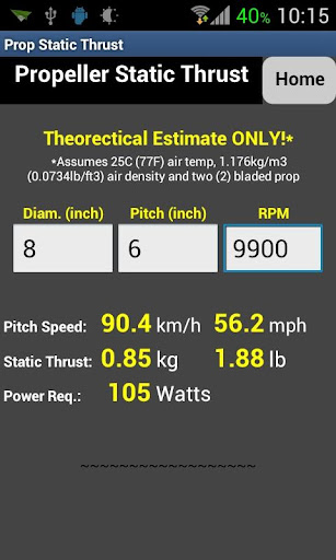
- Static thrust of a propeller in pounds or kilograms.
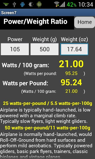
- Power to Weight Ratio in Watts-per-pound or Watts-per-100gram.

Examples:

a) Fly (or drive) for 11 minutes and 20 seconds, then recharge your 2200mAh LiPo, when finished your charger states that 1720mAh was returned to the battery. This app will then calculate that the average current draw for the flight was 9.11 amps, the discharge rate was 4.1C and you used 78% of the rated capacity of the battery. (Img #1)

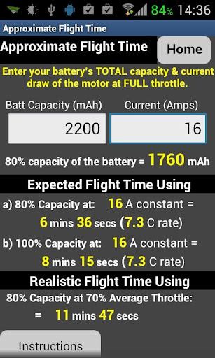
b) How long can you fly your plane safely? It is recommended to fly using only 80% of the capacity of LiPo batteries to maximize their longevity so using the 9.11A average from the example above, the full throttle current draw (you will need to measure this) is 16A, input 2200mAh and 16A into the app and it'll calculate that you should be able to fly (at FULL throttle) for 6 minutes 36 seconds until the battery is 80% depleted or for 8 minutes 15 seconds (also at FULL throttle) until it is 100% depleted. (Img #2)

A "Realistic" flight time for a plane is also calculated which works out to be 11 minutes and 47 seconds using 80% capacity and 70% average throttle, very close to the actual flight time in the first example.

For helicopters and multicopters the flight time is very dependant on what style of flight, but you can use this calulator's section to calculate the expected flight time in a hover.

Future plans: Add wing loading, cubic wing loading calculator, (suggestions?)

Disclaimer: The formulas used in these calculations come from various internet sources, with some variations added from my own experience. Your results may vary! While a lot of effort was put into ensuring accuracy, this app is not intended to be professionally accurate.

Comments & suggestions very welcome.

thanks,
Graham

P.S. Sorry it's not on iOS.

Read more…