Posted by Bill Bonney on August 2, 2015 at 10:30am
`
Hi, Just a quick note to people wanting to run APM Planner 2.0 on the Raspberry Pi 2 and don't want to build it from the source code. Community member Carpy has created a build to download.
It will run on any ARMv7 debian based platform, i.e. Ubuntu or Jessie, it's experimental so please report issues.
In light of the recent "Drone Slayer" in the news, we wanted to make a video to show what the common hobbyist drone can actually see from 200' up.
The drone slayer being William Meredith of Kentucky who shot down a drone he said was hovering as low as 10' over his yard. It turned out that after the drone pilot released his DJI Phantom 3 flight record, the drone was flying no lower than 193' above the house.
For this post, we want to let you inside 3DR by providing a look into the overall management process for a product like the gimbal. In the past we’ve focused mostly on technical matters, so we hope this is an interesting change of pace.
To cut to the chase: we were not happy with the performance of our gimbal over the past month while we’ve been tuning performance. So we decided to make it better, which means starting production this week (first week of August), not in late July as we last promised. This was a tough decision, to be sure - this post explains our logic.
So, first things first. The gimbal performance we were seeing wasn’tbad. In fact, we were right in that gray area where we could have reasonably decided to ship it right now. Our user tests on “naive users” - people that haven’t seen much aerial video - were uniformly positive. But with a trained eye, you could see movement in yaw in windy conditions.
So, we had a decision to make. Ship the gimbal as-is, or make it better. We decided to make some changes to make our gimbal work great, even if it meant taking a little longer to do so.
Decisions like this are always challenging because they aren’t black and white. At 3DR, one of our guiding principles is to prioritize the user experience (UX) over schedule over cost. We write it this way, as system of inequalities:
UX > schedule > cost
If you ever come to 3DR, you’re likely to see this little equation on whiteboards, in notebooks, in our internal docs.
We know perfection is impossible. Nothing we will do is ever going to be perfect. It’s hard to even write that sentence, because at 3DR, we strive for absolute perfection. Sounds pretty hokey, right? But that’s really the way we work.
And while we know we may not achieve perfection, there is some difficult-to-define point where the team can say, “That looks good. I’d put my name on that. Let’s ship it.” Not all companies have enough synchrony across engineering, design, ops, marketing and every other team such that the whole group hits that point at about the same time. At 3DR, we do have that synchrony. And we just weren’t feeling like the system was ready to go.
So specifically, what weren’t we happy with in the gimbal performance?
Over the past month, we’ve been tuning the performance to get the gimbals to stabilize well across the unavoidable variance of the manufacturing process. In so doing, we pushed our software control system really hard.
At some point in that tuning process, we got together to try and understand how much more performance we could get purely out of software.
Taking a step back: in any hardware/software product, whether it’s a thermostat, fitness tracker or drone, there’s an interplay between hardware and software engineering. The hardware sets the bounds of what software can do. Software can move fast to improve things but cannot operate outside the basic design of the hardware. Hardware is slower to develop, but can open up new territory for software performance and features.
In our case, the weight (or lack thereof) of the top part of the gimbal compared to the bottom part taxed our yaw motor’s ability to correct for disturbances in yaw. Basically, when the copter and gimbal get hit by wind or other disturbances, your video might look like it is vibrating or drifting from left to right. There’s a lot of technical detail here that I will omit, but our decision boiled down to: leave performance as-is, or find a way - a way that would add time to the schedule, no doubt - to address the yaw wandering.
We did find a way. Adding mass to the ends of the spider bracket - the piece that holds the dampers on the gimbal at the very top of the assembly - increases the overall mass of the top part of the gimbal. This allows the yaw motor to react to and correct disturbances hitting the bottom part of the gimbal where the camera lives, resulting in more stable video.
This improvement is relatively straightforward to implement in mass production (as much as anything is straightforward to implement in mass production), so we decided to go for it (after, of course, designing and testing the improvement).
It wasn’t an easy call. We know we could work on the gimbal forever and it would get better each day. We set strict requirements and checklists during our product development process to make that process as efficient and objective as possible. But at the end of the day, it boils down to a subjective, qualitative, ineffable judgment call - “That looks good. I’d put my name on that. Let’s ship it.”
We are very eager to get this gimbal out to you! Solo’s not complete without it. And we know not to let perfect be the enemy of the good. Actually, that’s not quite right - good isn’t good enough. I’ll rephrase: we know not to let perfect be the enemy of the great.
So that’s where we stand. We made some changes and started production. We'll check our product thoroughly before we ship the units. Fixing yaw wandering is only part of the story - there is so much more work that has gone into the gimbal (and is going into the gimbal, and will continue to go into the gimbal via software updates) that I don’t have room to describe here.
But the decision to improve the product and take the schedule hit vs. shipping as-is seems to me to be the most interesting thing to share with you all. We hope we’re painting a clear enough picture - perhaps with this information, you could even imagine yourself here at 3DR, doing this work, and making these decisions.
Thanks for your support and patience. We’re continuing to work hard on your behalf.
Finally, most important, here is some video that does not include any of the recent tuning, but has a version of the latest hardware. This was shot by one of the 3DR team, Jon.
From the great Eddie Codel, one of the first and best drone videographers, comes this!
The Flying Robot international Film Festival or FRiFF, is an open competitive film festival focused on aerial cinema created from the perspective of flying cameras, aka drones. Festival participation is open to anyone from around the globe. Drones, cameras and accessories will be awarded as prizes for winners in each of the 6 categories, as well as a "best of show" winner. Entry fees are $5-10, except the Student Film category, which is free.
Submissions are being accepted until the September 15th deadline. A panel of esteemed judges from beyond the Internet will select the winning films. Finalist and winning films will be screened live at a theater this November in San Francisco.
Just when you thought it couldn't get any more interesting. Along comes the Snotbot. A whale research drone that is being developed by Ocean Alliance and Olin College of Engineering. Here is a link to their kickstarter page:
We’ve already heard about drones being used to deliver pharmaceuticals to patients in remote locations, but scientists from Johns Hopkins University and Uganda’s Makerere University are now looking at the other end of the picture – using them to deliver remotely-located patients’ blood samples to labs in larger centers. According to a proof-of-concept study conducted by the researchers, the little unmanned aircraft should be able to do the job just fine.
Led by Johns Hopkins’ Dr. Timothy Kien Amukele, the scientists started with 56 healthy adult test subjects, drawing six blood samples from each person. Half of those samples (representing each person) were then carefully packed into an Aero fixed-wing drone made by 3DRobotics, and flown around in it for periods ranging from six to 38 minutes. The air temperature was around 70º F (21º C), and the drone didn’t exceed an altitude of 100 meters (328 ft).
All of the samples, both "flown" and "unflown," were then driven back from the flight field to the Johns Hopkins Hospital Core Laboratory. There, they were all subjected to the same 33 tests, which constitute the most commonly-performed blood tests.
Initially, there were concerns that acceleration upon take-off and vibrations caused by rough landings might affect the samples. As it turned out, though, the test results for individual test subjects’ flown and unflown samples were virtually the same. In some cases, there were differences when testing for total carbon dioxide levels, although this could simply be due to the amount of time that the blood sat around before being analyzed.
Amukele now hopes to conduct field tests in Africa, where clinics are often located long distances from decently-equipped labs.
"A drone could go 100 km in 40 minutes," he says. "They’re less expensive than motorcycles, are not subject to traffic delays, and the technology already exists for the drone to be programmed to 'home' to certain GPS coordinates, like a carrier pigeon."
A paper on the research was published this week in the journal PLOS One. The flight tests can be seen in the video below.
Facebook's shallow V-shaped plane has the wingspan of a Boeing 737. But even fully loaded down with communications gear, Aquila only weighs between 880 to 1000 lbs — about a third the weight of a Prius. "When deployed, it will be able to circle a remote region for up to 90 days, beaming connectivity down to people from an altitude of 60,000 to 90,000," the company said in a blog post. This means the planes will be flying at an altitude above commercial aircraft, and even above the weather.
FLYING ABOVE COMMERCIAL AIRCRAFT, AND THE WEATHER
This is how it will work: Facebook will have lasers on the ground that can locate the dome-shaped optical head located on the bottom of the plane in the air — basically shooting a laser at a dime-sized target that is more than 10 miles away. The plane will first hone in on the general location of the laser on the ground, proceeding to target it further and lock onto the location so that it can start beaming down the internet. Because the plane requires a connection with the lasers on the ground though, you might experience a slower connection when it's raining or cloudy.
The plane is built from two layers of lightweight carbon fiber material that sandwich a layer of foam. The planes are intended to stay afloat for three months at a time — presently the record for an aircraft staying afloat is two weeks — which is why the entire outside shell will be covered in solar panels. During the day, when they are fully charged, the planes will fly at an altitude of 90,000 feet. But at night, in order to conserve power, they'll float down to about 60,000 feet, going back up again the following day. This ensures a constant connection to the Internet, because they do not need to come down to be charged.
A BREAKTHROUGH IN LASER PERFORMANCE
Facebook says it has also achieved a significant breakthrough in the speed and accuracy of how these lasers work — they've lab-tested a laser that can deliver data at 10s of gigabytes per second, which is 10 times faster than the current state-of-the-art in the industry.
Facebook plans to use its Aquila fleet to create a linked network that will bring internet access to rural areas. Using a variety of data sources, Facebook can figure out where people are located physically, in order to then decide the most cost effective way to bring them connectivity. As with its internet.org project, Facebook won't provide access directly, and will instead partner with local carriers to offer services.
It's not a new achievement using wifi as Telemetry but this UART to WiFi module has really long range (up to 400 meters), and unbeatable price. Very small form factor (about 2cm x 1.5cm) and light (3 gr). Great for the small sized UAVs. And your Smart Phone or Tablet will become a GCS with no additional hardware. And with module's available GPIOs it's functionality can be increased (PWM, I2C sensors) you can drive LEDs or get sensor data over wifi.
I've been experimenting with new ESP8266 UART to WiFi module and happy to announce you that it can be used as Telemetry module. It should work on all MAVlink devices that uses Serial communication. I tested with ESP-03 and APM 2.6 (3.2) and range is acceptable for Follow Me, or Guided missions. it works reliable enough and its really cheap, start as low as 2,5 $ at several stores (its a 3.3v device you will need a good (about 300ma) power source). I think APM 2.6 users should receive at least a one last bug fix release (several reports indicates 3.2.1 has some issues with altitude calculations), of course you can compile your own verison.
For those who are interested, I can provide APM:Copter 3.2 (not 3.2.1) firmware with the fix. I am happy with it, doing some great auto flights, checking parameters, follow me flights, you can fly your UAV even without RC controller, directly from your wifi enabled GCS.
Unmanned aircraft can be put to effective use in humanitarian situations, but a code of conduct is needed to make sure they are used safely and efficiently
UK Guardian, July 28, 2015
After typhoon Haiyan wreaked havoc on the Philippines in 2013, killing more than 6,300 people and destroying farms and villages, several relief groups flew drones over the affected areas to survey the damage, identify blocked roads and find displaced people.
But the drone operators didn’t share the information they gathered with local authorities or other relief organisations, says Patrick Meier, who was in Manila doing humanitarian work with the UN at the time. Many of the drone teams didn’t even know about one another, making their work inefficient and even dangerous.
These problems highlight the need for a code of conduct and best practice for drone use in humanitarian situations, says Meier, who founded the Humanitarian UAV Network to move toward that goal. Meier was one of the speakers at a recent symposium on drones in Washington, which discussed many uses of unmanned aircraft in humanitarian situations but highlighted the need for regulation. Meier says the Humanitarian UAV Network plans to launch a set of guidelines next month that will make sure drone use in humanitarian settings is safe, coordinated and effective.
Though unmanned aircraft are best known for their military uses, smaller drones are becoming popular with photographers and others with a few hundred pounds to spend and a desire for aerial images. In June, police in London seized a drone flying over Wimbledon, two days before the tennis tournament was set to begin. In July, efforts to drop water and retardant on rapidly spreading fires in southern California were stymied by drones hovering over the flames, because of the risk to firefighting aircraft. Also in July, a teenager in Connecticut posted a video of a homemade drone firing a gun in the woods.
But there are many ways drones can be used for good, says Peter Rabley, property rights director for the Omidyar Network, a philanthropic investment firm. Drones can democratise data collection and “help make the world a better, safer place”, he says.
The flying wing design I have been working on for some time now has been slowly evolving as I have learned more about aerodynamics and expanded my skill set with modelling tools of various forms. I have recently completely re-surfaced my design with new aerofoil sections and better, more consistent surface transitions and have been experimentally analysing the results with CFD, courtesy of OpenFOAM. I want to present some of the results here to share.
The lead image is the latest design iteration analysed in OpenFOAM at close to stall angle of attack and the following are a couple of renders of the latest surfacing.
Along with developing methods, I have learned a few things about what makes flying wings tick and how they can be better optimized, at least in the genre that I am pursuing. Some interesting, I hope, insights follow:
Aerofoil selection appears to be the one thing many obsess over when designing a flying wing, but I have found it is only a very small part of the equation and gains made here in two dimensions can be easily lost in the transition to 3D. Many flying wings appear to fly with a large amount of elevon-induced reflex, demonstrating that aerofoil selection alone is inadequate. In a sense, it is equivalent to a large decalage angle to compensate for a low tail volume which is a pretty inefficient way of achieving the design objectives.
I have several iterations of aerofoil in this design, a root foil whose origin is now unclear and a tip foil which started as a symmetrical NACA foil, but wound up with a little camber in the end. Much of the initial development was done in XFLR5 but the CFD proved illuminating in areas not possible with panel code alone.
Washout has proven to be a much more powerful tool to add pitch stability and, in both geometric and aerodynamic senses, has surprised me in how much is actually required to do the job. I have about 7° geometric in this design and in addition have an inverted aerofoil section (a NACA 1308)) for the wingtip to add a relatively large amount of additional aerodynamic washout. Despite this, the undeflected trim speed of this design is of the order of 24-25m/s At this Reynolds number scale, washout has an advantage over reflex that hopefully will become clear shortly. The next image shows the airframe at about 24.5m/s and demonstrates pretty clearly the lift distribution through the downwash trajectory.
One of the big hurdles of flying wings is to maximize the CLmax value which determines the maximum wing loading and landing speeds. Despite the large washout, the stall consistently begins around the tip which is where much of my attention has been focused.
Early on in my investigations I discovered that wing sweep can have deleterious effects on stall performance. In hindsight, I was rediscovering what the Russians already knew from their MiG15 design onwards and attempted to alleviate with those huge wing fences. The effect of wing sweep at stall is a reverse spanwise flow on the upper wing surface. In part this is caused by a changing spanwise pressure gradient as the AoA increases where the inboard high pressure zone is interacting with the lower pressure zones further outboard. The boundary layer flow model below helps visualize this flow regime quite dramatically, although at this Re scale, I predict that it tends to form a laminar separation bubble/vortex running span-wise along the wing surface.
(MiG-17 showing clearly the wing fences for controlling reverse span-wise flow at high alpha)
As demonstrated in the above illustration, the design optimization of the elevons is an area that is ripe for further DIY exploration. I have found that traditional full-span elevons are counter productive because as the elevon reflex is added, the aerofoil section CLmax is reduced. I have instead experimented with various size and proportion elevons at the wing tips, leaving the inboard wing section unmodified with control surface deflection. This elevon design appears to do the job of increasing the aerodynamic washout of the wing as much as adding reflex, both effects working in parallel to reduce its trim speed accordingly. Unfortunately the foil section modified by the deployment of the elevons tends to be negatively affected giving rise to a large adverse pressure gradient early in the chord causing flow separation bubble formation and loss of lift - the bubble in effect causing a dramatic thickening of the effective aerofoil section with a near total loss of reflex. For this reason, I think washout provides some interesting advantages over reflex at this scale.
To alleviate this separation bubble phenomenon, I have experimented with the use of "spoilerons" - in effect a kind of inverted split-flap design. The top surface of the foil section is deflected upwards leaving the bottom surface unmodified. By opening a gap at the leading edge of the spoiler surface as it is deployed, the negative pressure behind the spoileron tends to improve the pressure gradient along the foil boundary layer helping to delay the inevitable separation somewhat. The spoilerons have also appeared to be extremely effective at quite small sizes relative to conventional flap-type elevons and have led to a minimal impact on drag at low angles of attack.
Spoilerons have not entirely solved the problem of wingtip flow separation so I have added leading edge slots in this latest design iteration. I would not consider them yet optimal, but they tend to add about 4-5% to the CLmax as they stand. They also may have had a non-trivial impact on CD0, but I haven't yet enough data to demonstrate or quantify this.
The results so far predict a best L/D just shy of 12:1 at around 16-17m/s with a span of 975mm and a 1.2kg AUW. There is a small non-linear effect with weight variation due to Reynolds number effects at this scale, some of which can also be seen in the measured drag polar data, where drag at high AoA increases much more sharply than predicted by conventional drag coefficients. This is almost certainly a result of separation bubbles forming - at least theoretically. I don't wish to imply that the CFD data is infallible.
Despite the use of CFD, I haven't yet managed to achieve my theoretical design goal of 10m/s stall speed at the design weight (1.2kg). It currently sits somewhere in the region of 11m/s for a CLmax of 0.65-ish. Note that the reference area is close but still a little unclear at this point due to the "flowing" wing planform so the lift coefficient data probably isn't directly comparable.
I am doing further analysis based on these aerodynamic characteristics to establish propeller selection, range, payload, climb performance, battery size etc, however initial estimates are very encouraging, putting range at or exceeding 100km on 8 x NCR18650B's. With careful airframe design, this allows for at least a 250g payload as well as both video (5.8GHz) and telemetry (915MHz) data links aboard.
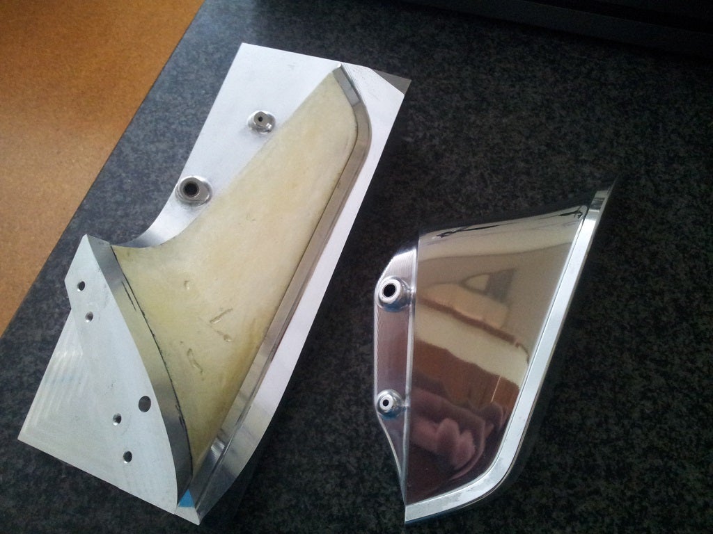
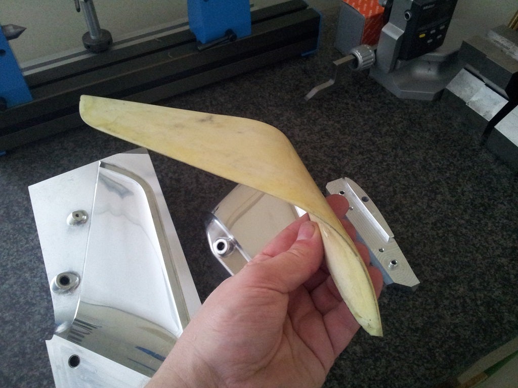
I envisage a fully moulded composite airframe to meet the weight targets, make it robust and to yield a good surface finish for drag minimization. Along side this work, I have been experimenting with some construction techniques on a winglet sample. The results of this experimentation will help drive some of the design and strutural analysis. The potential for high quality surfaces is definitely there but will take some process development and an amount of overly sticky fingers to achieve.
There are a bunch of detail design issues yet to resolve, not least being the manufacturing methods for a robust spoileron at an affordable cost. The non-trivial issue of downward control surface deflection has also to be addressed in mechanical and aerodynamic terms.
Unfortunately as this is all self-funded to date, so progress will continue apace, where the pace will be more tortoise than hare. I hope to publish further info about how I've gone about range analysis, propeller selection as well as some more details about how I've used CFD.
Thanks for reading if you've got this far. I hope it's been interesting
Tricopters, quadcopters, hexacopters, octocopters, etc.
The drone-world is evolving quite fast and nowadays one can see very curious vehicles and configurations that surprisingly (or not) are able to fly properly.
This is due to the possibility that some open source autopilots like Pixhawk or APM offers to develop customized control algorithms for unimaginable vehicle configurations. The majority of control laws are based on PID controllers that allow to even overactuated systems, as octocopters, to be controlled “easily” as the physics of vehicle is “simple” but...
What if the autopilot has to deal with highly overactuated systems whose actuators have very different dynamics and effects?
Our aim as DroneBoX team is learning, researching and developing innovative ideas of unmanned system for logistics purposes. Our first prototype, XXCopter, aims to be a technology demonstrator for warehouses logistics capable of picking up loads from vertical storages and transporting it to a specified location inside the same warehouse.
In terms of technology, it is a 9dof of control tricopter controlled by the throttle level of each motor and the movement of two joints in each arm, using advance control techniques like Non-linear Dynamic Inversion or Control Allocation and open source autopilot like Pixhawk.
Note that this system is a real control challenge not only because the dynamics of the control parameters are really different but also because the inertia and mass properties change when a control order is applied. In addition, one must consider the gyroscopic effects, non-linearity, etc.
We let you with some of the tests carried out so far with the arms:
Do you want to see more details, the assembling process, code, some test and the results?
Stay tuned!
We will release soon some news about our second prototype, which aims to be a true game changing vehicle for last mile logistics and more.
Congrats to the ETH Autonomous Systems Lab for this milestone with a Pixhawk-powered fixed wing drone. Next stop: crossing the Atlantic! From the team:
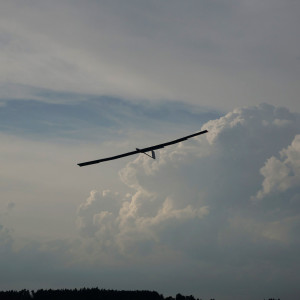
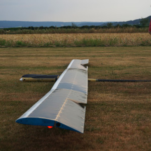
Two weeks after having demonstrated AtlantikSolar’s first 24-hour flight , the fixed-wing team of ETH Zurich’s Autonomous Systems Lab has reached another milestone: A continuous flight of its 6.8kg AtlantikSolar Unmanned Aerial Vehicle that spanned a total of 2316km and 81.5 hours (4 days and 3 nights) and has broken the flight endurance world record in its class. See the video below for an illustrative overview of that flight test.
More specifically, this fifth test flight of the AtlantikSolar 2 (AS-2) UAV
sets a new world record for the longest ever demonstrated continuous flight of all aircrafts below 50kg total mass, and is also the longest-ever continuous flight of a low-altitude long-endurance (LALE) aircraft (the previous record being a 48-hour flight by the 13kg SoLong UAV ).
is the second-longest flight ever demonstrated by an Unmanned Aerial Vehicle (behind Airbus Space’s 53kg Zephyr 7)
is the third-longest flight ever demonstrated by a solar airplane (behind Airbus Space’s 53kg Zephyr 7 and the 2300kg Solar Impulse 2)
is the fifth-longest flight ever demonstrated by any aircraft (both manned and unmanned).
In addition, the flight is a first important milestone to verify the UAV’s ability to stay airborne for multiple days while providing telecommunication services in large-scale disaster-scenarios or live-imagery during industrial sensing and inspection missions.
Flight Summary
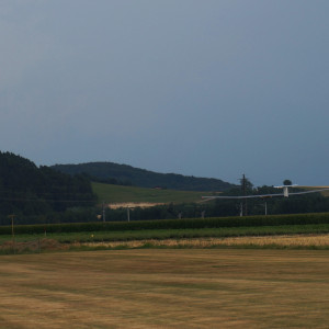
The flight was performed at the Rafz, Switzerland, RC-model club airfield from July 14th-17th, of which the first three days provided very good sun conditions. Take-off was performed via hand-launch at 09:32 on July 14th, and after 2316km and 81.5 hours – 4 days and 3 nights – of flight, the aircraft landed safely and with fully charged batteries at 18:56 on July 17th. The fully charged batteries would in theory have enabled to continue the flight through the night again. With the exception of take off, the aircraft was in fully-autonomous operation 98% of the time, and less than 2% in autopilot-assisted mode via its Pixhawkautopilot.
The long-endurance flight provided very helpful insights on flight performance: The average level-flight power consumption in calm conditions (e.g. during night) was shown to lie in between 35-46W. Maximum power input throuh the 88 SunPower E60 cells during the day was around 260W. With this performance data, the aircraft managed to achieve fully-charged batteries (100% SoC) at around 13:05 local time, and thus even before the time of maximum solar radiation (solar noon, occuring around 13:30). After flying through each of the three nights, the aircraft on average reached a minimum state of charge of 35% at around 07:45 local time and thus still shows sufficient energetic safety margins for worse environmental conditions (such as longer nights, cloud cover or winds).
The flight also subjected the aircraft to a wide range of environmental conditions. Among them were thermal updrafts during the first evening/night (causing a remaining state of charge of 40% ), and downdrafts during the second night (remaining state of charge 32%). The last hours of the flight were marked by upcoming thunderstorm clouds and the strongest winds – up to 60 km/h – the aircraft was ever subjected to. Although the ground station was partially damaged by the winds, the airplane could be landed safely in autopilot assisted mode when the winds had calmed down a bit.
Future work
Having demonstrated the multi-day endurance capability of the bare UAV platform, the AtlantikSolar UAV project will now focus on extended endurance flights with payloads including optical and infrared cameras as well as atmospheric sensors. These payloads will also be carried during a long-endurance and long-distance mission of more than 12 hours and 400km that is planned for later this year in the Brazilian rain forest.
Further information
Detailed design and technical information on the UAV platform can be found in “Oettershagen P, Melzer A, Mantel T, Rudin K, Lotz R, Siebenmann D, Leutenegger S, Alexis K, Siegwart R (2015), A Solar-Powered Hand-Launchable UAV for Low-Altitude Multi-Day Continuous Flight. In: IEEE International Conference on Robotics and Automation (ICRA)”
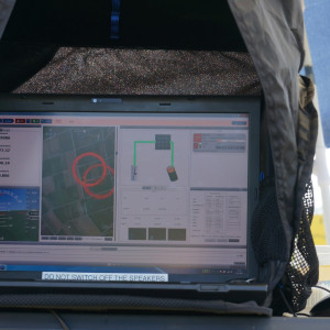
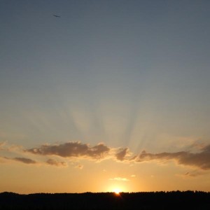
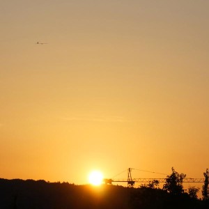
Some more impressions from the flight were broadcasted live through our twitter account
T=0 hours, Handlaunch of AS-2 for the record attempt
T=2 hours, shortly after launch. Only occasional clouds, but strong winds up to 40 km/h
T=8 hours, monitoring the aircraft and its energy generation and storage system. Batteries are fully charged here.
T=36 hours, flying towards the night. Will we make it?
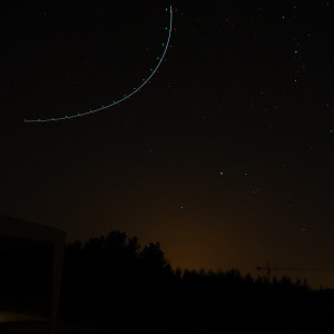
T=41 hours. Drawing circles into the night using the onboard position indicator lights.
T=70 hours, sunrise on the third and last day.
T=81 hours, thunderstorm clouds and winds up to 60 km/h make the landing very challenging.
T=81.5 hours, landing.
T=81.5 hours. Landed.
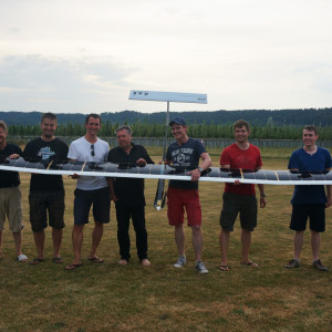
T=81.5 hours. A happy team after a 81.5 hours record flight.
Acknowledgements
This research was funded through ETH Zurich’s internal resources, private supporters, and the European Union FP7 Search-And-Rescue research projects ICARUS and SHERPA . In addition, multiple project partners and collaborators have contributed towards making this important milestone possible, and we’d like to thank all of them for their various and ongoing support. Finally, we are grateful towards the Rafz model aeroplane club for providing the airfield and the Aero Club Asas da Planície (Portugal) for providing the backup airfield!
Pilots: Rainer Lotz, Adrian Eggenberger, Philipp Oettershagen, Bartosz Wawrzacz. Development and Operations Team (Autonomous Systems Lab): Philipp Oettershagen, Rainer Lotz, Amir Melzer, Thomas Mantel, Bartosz Wawrzacz, Konrad Rudin, Thomas Stastny, Raphael Schranz, Jan Steger, Lukas Wirth, Dieter Siebenmann, Dr. Stefan Leutenegger, Dr. Kostas Alexis, Prof. Dr. Roland Siegwart.
We wanted to share a fun video we made recently. Our drones can interact with obstacles and humans, which is opening amazing new applications, be it for accessing hard-to-reach places or for having fun with them.
We achieve that through a passively rotating protective cage an control algorithms that keep the drone stable at all times. More than just a protective cage, the fact that it can rotate really prevents collisions from disturbing the orientation of the drone (see animation below). Also, because the cage is decoupled, the apparent inertia is quite low and the drone is very reactive.
Hope you enjoyed, we look forward to show you more in the near future !
Flyability is a young spin-off from EPFL based in Lausanne, Switzerland. Please read more at www.flyability.com if you're interested.
Cheers,
Adrien
PS: We're currently shipping evaluation kits to professional users.
PS2: We're always looking for talented engineers (jobs@flyability.com)
[IEEE CSS Video Clip Contest 2015 Submission] This is a video introduction to controlling self-driving cars, specifically using PID-control. Special emphasis is placed on how the proportional, integral, and derivative gains affect the performance of the vehicle.
After we demoed a little five-channel "AutoPylot" program on a Naze32 with ODROID companion board, our friends at A2USA, Inc . asked us whether we could do the same for the Pixhawk that they use for flying their big birds. We started modifying our MSPPG parser generator to output MAVLink messages, but soon stumbled across some awesome gists by Christopher Vo that showed a better way, using Tridge's pymavlink.mavutils library. Thanks to their work, we were able to create a little Python class that automates much of the programming.
As with our ARDroneAutopylotand PyQuadSim packages, the autopilot kicks in when you hit a switch (default = channel5, which I've configured as SC on my Taranis), and automatically calls a Python method that you write, which returns the other four RC channel overrides (pitch, roll, yaw, throttle). By overriding the getChannelsPos1() and getChannelsPos2() methods, you can create two different automated behaviors based on the two non-default switch positions. Our code includes a simple example that you can run from an ordinary computer, where getChannelsPos1() cycles the throttle up and down, and getChannelsPos2() cycles the roll. To help avoid accidents, these methods will not get called until the switch has first been reset to its default position. Because our goal is to put this code on an ODROID to support missions like the one simulated in this video, we have also included an ODROID-specific copy of this example in the repository.
To run on ODROID, you'll need an inexpensive Pixhawk telemetry cablefrom 3DR and a level-shifter boardto step up the ODROID 1.8v UART to the 5v required by the Pixhawk's telemetry ports. (We followed advice from A2USA about not using the simpler USB connection, whose rigid cable can transmit vibrations from the ODROID to the Pixhawk). Our video shows us using an older level shifter on a breadboard, but as soon as our new level shifter arrives from Sparkfun, we'll make up a little cable to go directly from the ODROID to the Pixhawk through the shifter. The video also shows 5v power from a Castle Creations CC BEC, but on an actual vehicle the 5v would likely come from the BEC output of one of the Electronics Speed Controller (ESC) units. We're going into the Pixhawk through its TELEM 2 port, so TELEM 1 can be used for the 3DR Radio talking to Mission Planner on our Windows box.
WARNING: We have not flight-tested this system and will doubtless encounter bugs once we do. Obviously you should (1) know how to program in Python and (2) thoroughly bench-test your autopilot solution before flying.
Congrats to our friends at Conservation Drones, whose collaboration with International Union for Conservation for Conservation of Nature (IUCN) and Liverpool John Moores University on using computer vision to spot chimpanzee nests from the air (using APM-powered drones) has now been published in the American Journal for Primatology. Counting nests is easier and less disruptive than counting the chimpanzees themselves. The primates build new nests each night and the nests are visible for about a month before they deteriorate, so it's pretty easy to use such nest counts to derive a population estimate.
As their population has plummeted in the last two or three decades, the International Union for Conservation for Conservation of Nature (IUCN) has come to class chimpanzees as endangered. Monitoring where they live deep in the tropical forests of Africa is critical, as it allows conservationists to detect changes in these tiny populations and identify when they might be becoming dangerously low.
Such monitoring has traditionally required expensive and time-consuming ground surveys, as researchers spend hours traipsing the terrain by foot and counting nests. And because the animals often build these nests beneath the canopy, there was an degree of skepticism as to whether aerial surveying would work.
But a new study carried out by researchers from the IUCN and Liverpool John Moores University has demonstrated that these domiciles can be picked out by drone. The researchers used low-cost drones to snap a large number of photos in a 20-minute flight over an area that would otherwise have taken ground surveyors hours to cover. In viewing the images the researchers were able to detect nests, demonstrating a new technique that could save conservationists time and money.
"The results of this study show that drones can be a new tool to determine faster whether chimpanzees are present in a certain area," says Alexander van Andel from the IUCN and one of the study's co-authors. "In addition the study shows that habitat suitability can be determined by drones by identifying tree species which are important in the chimpanzee diet."
Contributors to 2.0.18 release are (in no particular order)
martinjuju, Peter Barker, mirkix, Lucas De Marchi, Andrew Smith, Mark Sutherland, Andre Kjellstrup, Markus Reitboeck, Александр Фролов, mrpilot, Michał Wróbel, nbrachet, labtoast, Michael Carpenter & Chris Anderson
I'd like to say thank to everybody that has made a contribution to project. Good work!
We were running some tests on RTK / DGPS / GPS these two weeks. Thought it might be interesting to share our results in image format, although the accuracy numbers are already well known.
Test setup is as below:
Below is RTK result from 3 different days; black:20150716, green:20150721, white:20150723
As RTK accuracy is centimeter level, they overlap pretty well at this zoomed-out view.
White line RTK result is used as frame of reference to compare DGPS and GPS results
Below is DGPS result from 2 different days; red:20150716, cyan:20150723. Result is quite good since distance from DGPS base station is only 1.5Km.
Below is GPS result from 2 different days; red:20150716, cyan:20150723.
The shifted red track is due to ionosphere error that changes over time, which accounts for major error in a typical 2.5m CEP accuracy GPS receiver. It just happened that ionosphere error was less on 20150723, resulting in the cyan track closer to the correct white track.
What’s noteworthy is that the two rounds made on each day overlap quite well, meaning that the GPS receiver is fairly precise, just that the accuracy is still 2.5m CEP.
Below is 20150723 result with another popular GPS receiver brand for comparison.
Overlapping all previous plots, below figure results; giving a glimpse of potential GPS error on day to day basis.
This video shows work done this summer by Washington and Lee student Conan Zhao '16. Conan used the PyQuadSim and OpenCV Python packages to create a realistic V-REP simulation of a quadcopter returning to its takeoff point using a combination of GPS and visual information.
This is the sort of thing T3 entrants get up to, well done!
HABLEG has a mass of 7kg, a wingspan of 3m and can carry an additional payload of up to 3kg. The flight was conducted at the rocket base ESRANGE in northern Sweden, where the glider was lifted to an altitude of 20km by means of a helium balloon. Upon release in the low density atmosphere, a central challenge was the transition from freefall to horizontal stratospheric flight. Having achieved this critical part of the mission, the plane was then automatically guided back to base while performing it´s test flight program. All characteristics of the plane could be tested and validated within the one hour glide phase.
Touch-down occurred less than 50m away from the launch site which makes it the first successful flight of this kind in Europe.
This is the most elegant HAB Glider launch I have ever seen!