All Posts (11086)

Sort by

Hi everyone,

I just wanted to share with you all the news that our video stabilization software is now live and ready for download! 


We set out a few years ago to transform the very time-consuming and difficult stabilization technique that I was developing into an automated piece of software.  To say it's been a lot of work would be a huge understatement.  But I must say I think it's been worth it.  

We feel that this will open up a huge range of possibilities for drones, as you'll no longer need to carry the weight of a brushless gimbal, the beefier motors to lift that heavy gimbal, and the heavy higher-voltage li-po to power those motors in order to get solid, smooth footage. 

Who knows, we might even see a renaissance of the servo gimbal!  If you take a look at our gallery page you can see the full before and after clips of many servo gimbal flights.

And we've got no doubt this is going to make drone races look that much more amazing.

Check it out at ReelSteady.com.  We are super-excited to see all the imaginative uses people will find for this new tool.

Hope you like it!


-R

Read more…

Archaeology and UAVs

ireland drone photo

Thanks very much to this site and to 3DR for all of your technical know-how and insights over the years. From Archeology.org

Drones Help Find Medieval Irish Sites

ST. LOUIS, MISSOURI—Thomas Finan, an archaeologist and history professor at Saint Louis University, has conducted excavations in the northern part of Ireland’s County Roscommon over the last two decades at sites including an ecclesiastical complex, a moated stronghold, and a number of ringforts. In addition to other technologies, he is now using aerial surveys taken by drone aircraft to help locate new dig sites with the potential to illuminate medieval social dynamics in the area. "We have collected an unprecedented amount of digital data," Finan said in a press release. "The 3D landscape data allows us to see minute changes in the topography that can be defined as structures and human occupation. The digital data collected with the geophysics is then wrapped around that 3D data to give us an amazing understanding of what is there without sinking a spade." To read about new ideas on when the Vikings came to Ireland, go to “The Vikings in Ireland.”

Read more…
3D Robotics

ZNcldMcGxchGJ8PiJ2R_fCL5XQ5uxbZ2spoTMPwYWyniBzhiSjg-3itvDO-gXVmee_gj5eJNtLsRgtJDXIJmf9LKRhBaJQ6-wnjkbaA1mcLtzITHUOtvuwHRtOFMdCIk6xmZkmc

Hi Everyone -- here's a big (and good!) status update on the Solo gimbal.

The gimbal production pilot is finished and mass production has begun! This means units will be leaving the factory this week. A software update will be timed to go out soon with a variety of updates, and more software updates will follow quickly on the heels of gimbals getting into customers’ hands. That should happen in all likelihood the week of 8/24. (Why can’t we predict this in-hand date exactly? Gimbals are released on a rolling basis, and as they leave the kitting facility in China, they enter various modes of transport, including UPS, FedEx, etc., that all have variability in their delivery dates. Customers who have pre-ordered units from both 3DR and our partners should start seeing them next week, but it will take a couple of weeks to get to everyone.  Retail shelves will likely see stock in a few weeks, mid-September or so.)

Here's some sample video from the latest software build (there will be one more build before gimbals arrive with customers early next week). This is the baseline -- it's only going to get better from here!

Of course, there is much more to the story than having gimbals shipping out of the factory.

Our software team is cranking and there’s a lot of performance we have gained recently. This also means that we’ll continue to release updates that improve performance over time.

Our life test data continues to look strong. That means the gimbals should last a long, long time.

User testing continues to go well. Regular people are able to set up the gimbal and get it flying quickly and easily.

Our customer support team is trained up and ready. The how-to videos are shot and ready to go into the Flight School portion of the app. We have refreshed the app to incorporate the gimbal and improve overall usability. The app UI has been made more elegant; Solo will automatically turn itself off if it has a wonky landing or crash (which should happen rarely!) - stay tuned for a number of updates.

We're excited for everyone who has preordered to get their hands on their gimbal in the coming weeks! We deeply appreciate your patience throughout continued development, and we can't wait to see the amazing videos you create.

For those of you who have preordered in the initial months with directly with us, Vu, who heads customer support at 3DR, will be sending out a reauthorization email with some final instructions. It’s important you follow them, we won’t be able to ship your gimbal without it! Please be on the look out for it.


Read more…

Ammunition Distributor Takes Aim At Drones


Drone-Munition.jpgSnake River Shooting Products, an ammunition and firearms products distributor, is now taking aim at drones, literally. Their new Drone Munition is being sold with the fear-mongering tagline, "prepare for the drone apocalype! The invasion of privacy!" When asked on Facebook, a representative of the company explained that they are not encouraging the potential Federal crime of shooting down unmanned aircraft. Instead, they are merely selling a self defense aid. If you would like to leave them your thoughts, I have linked to the Facebook post here. 

Read more…
Developer

FPV Racing using Arducopter

3689663048?profile=original

Hi All,

This is intended to help people who are interested in using Arducopter for FPV Racing and/or mini quads.

Personally I started using Arducopter because I wanted to fly FPV and get aerial video of my 4wd trips. I also wanted the comfort of RTL and Loiter to get me out of trouble and help me learn. Arducopter's focus at the time was autonomous flight and I was told that we don't have time to focus on manual flight, other boards like the KK were for that stuff. My argument has always been that making Arducopter capable of aggressive manual flight provides the foundation of robust autonomous flight.

Three years later so much has changed. Arducopter is expected to handle the most serve weather conditions the hardware can fly in, while carrying out a way point mission with the grace of the most skilled pilot (I don't believe we are quiet there yet). This has come about by focusing on achieving the best control we understand is possible. This focus on the basics of control means that Arducopter is a very capable FPV and acrobatic controller.

There have been a number of advancements over the last three years that have taken us to this point.
1. Introduction of the Rate D term,
2. Earth frame to body frame conversion,
3. The Stability Patch,
4. IMU filtering understanding and improvements,
5. Our first stabilized ACRO http://diydrones.com/profiles/blogs/acro-for-ardupilot-3-1,
6. The Onion rewrite,
7. The post Onion ACRO rewrite,
8. Autotune,
9. Thrust linearisation and current limiting,

And on the immediate list of things to do

10. Conversion to Quaternion attitude controller,
11. One Shot support.

Some of the key people that have taken an active interest in ACRO and it's development over the last 3 years are Robert Lefebvre (responsible for the first stabilized ACRO algorithm), Randy Mackay, Jonathan Challinger, Paul Riseborough, Josh Welsh, Bob Doiron and many people I can't name who gave feedback and risked their copter testing ACRO.

So enough of the reminiscing about old times.

My role on the Development team focuses primarily on the control and navigation code in arducopter. While many people see Arducopter as targeted at larger copters and autonomous missions, I have found small powerful quads to be the best test platform for this development. Copters in the 250 to 300 size range not only crash well, there agility and power make them very sensitive to controller design and tuning. Further, the standards we aspire to, are reaching a level where the only way to properly test them is with FPV and a combination of on board video and logging. On top of all that, they make testing FUN :)

So this has been my primary test platform for the last 12ish months (after one of many hard landings):

3689663123?profile=original

Name: QAV 250
Weight: 624g
Motors: Baby Beast 2206 2150 kV
Battery: 1300 mAh, 3s
Props: HQProp 5x4.5 Bullnose
Power: 480 W
Current: 40A continuous and full throttle
Thrust: 1.68 kg Thrust at full throttle

My setup on the QAV is relativly low power compared to what some of the best pilots are flying so I decided to build something a little more extreem while ensuring I didn't need to continuously replace puffed batteries and burnt out ESC's and motors. I came up with this:

3689662984?profile=original

Name: My kids call it Willy for some reason (don't ask me!)
Weight: 940g
Motors: Sunny Sky 2208 2600 kV
Battery: 2200 mAh, 4s
Props: Gemfan 6x4.5, Gemfan 6x4 Bullnose, HQProp 6x4.5, APC 6x4E Speed, Quanum 6 x 4.5 Carbon (still experimenting)
Power: 1.4 kW continuous, 2 kW for short bursts
Current: 120 A continuous, 160 A for short bursts
Thrust: 4kg continuous, +6kg for short bursts
Has a custome 200A 4s power module based arround the ACS758ECB-200U-PFF-T.

Setting up an FPV racer

Vibration

Vibration is a major issue on these copters. They tend to be small, light, stiff, operate at high speed and rpm, with relatively large surfaces under the props. This means that lots of vibration is created and it is directly transfered to the base of the autopilot. There are two main sources of vibration, the first is when the high pressure wave created by the prop hits the top of the arm. The second happens during fast forward flight. When the blade of the propeller travels forward into the airstream it creates significantly more lift than when it is traveling with the airstream. This causes a torque on the shaft of the motor twice for every time the propeller rotates. Both of my copters create enough vibration to cause clipping on the accelerometers at full throttle.

My personal rule is I don't add vibration dampening unless it is needed and most of the time it is caused by loose screws or overly flexible frames. While my QAV 250 doesn't experience enough clipping to need any special attention, Willy creates an amazing amount of high frequency clipping that can destroy our attitude estimation (the autopilot doesn't know what direction is up). The solution I use (thanks Paul) is four 11 mm squares of Latex Foam. The foam below doesn't come with tape so I add thin double sided tape to each side before I cut it into squares.

Vibration handling
http://www.hobbyking.com/hobbyking/store/__26457__Anti_Vibration_foam_Orange_Latex_190mm_x_140mm_x_6mm.html
or
http://www.hobbyking.com/hobbyking/store/__26456__Anti_Vibration_Foam_White_Latex_Foam_.html

Below is my vibration isolation in Willy, it is worth pointing out how I kept the cables away from the Pixhawk and ensured any cables connecting to the Pixhawk had a nice bend to minimize vibration transfer from the frame.

3689663138?profile=original

Another serious source of vibration is vertical slop in the motor bell. This means that as the motor rotates the magnetic force that rotates the bell also causes it to jump up and down against the thrust of the propeller. Without the propeller attached this sounds like sand in the bearings. You can easily feel this my moving the bell up and down with your hand. If you feel a small amount of movement or hear a tick every time you move the bell, then you need to adjust the bell on the shaft. I do this with a press I made with the help of Sneezy:

3689663071?profile=original

It is based on this device and some square steal tube.
http://www.hobbyking.com/hobbyking/store/__11447__Turnigy_Pinion_Removal_Tool.html

If I find a problem motor I loosen off the grub screw and very carefully press the bell down over the shaft until I no longer detect any vertical movement of the bell.

ESC Setup

Larger copters don't require the fast response of Simon K and BLHeli and can result in sync loss or burnt motors or ESC's. It is especially important to ensure the ESC can handle not only the average current your motors draw but also the much higher peak currents caused by the aggressive response of the Simon K and BLHeli firmware. The only significant advantage these firmware provide large copters, especially lightly loaded, is active breaking.

For small FPV racers Simon K and BLHeli provide massive benefits. These copters have high powered motors and small propellers that are more an capable of taking advantage of the faster response time these firmware offer. There are three areas these firmware offer significant improvements.

The first is the removal or reduction of input filtering. This means that your commanded input to the ESC is directly passed to the motor without a slow ramp. The slow ramp up on standard ESC's keeps the peak currents from becoming too large and damaging the ESC and motor. That is why we need to make sure your ESC and motor can handle these short but high current spikes.

The second is active breaking. If you take your ESC and pump the throttle you will notice that the motor speed up much faster then they slow down. This is especially obvious on large props that are very lightly loaded because the drag on the propeller is very small and their momentum large, they don't tend to slow down quickly causing control and tuning problems. On small copters active breaking causes the motors to slow down almost as quickly as they speed up. The result is significantly more control torque on the air frame, provided with less delay.

The final improvement is One Shot (also an advantage of CAN bus ESC's). These ESC's speed up the communication between the autopilot and the ESC. The reduced latency makes it possible to have higher PID gains and tighter control. It is sort of like reading this blog post and being able to skip all the woffle to get to the good bits. :)

This is a screenshot of my BLHeli setup. You can see I have enabled Damped Light. This is the active breaking feature of BLHeli. Arducopter doesn't support One Shot yet but we are working towards that and I will let you know how this improves control when we get it going.

3689663214?profile=original

Center of Gravity (CG)

It is very important to get the CG right on any copter. The smaller the copter the more precise you should try to be. For a dedicated racing copter there it may be worth moving the CG slightly forward to counter what I understand is referred to as Propeller-Flapping-Torque. This is the tendency for the propellers to want to rotate away from the incoming airflow like an umbrella on a windy day. You can see the effects of this in forward flight by comparing the motor outputs. You will see that during fast forward flight the rear motors tend to have a higher setting than the front motors. A slightly forward CG can even up this imbalance and let you get the most power out of your motors.

The ideal CG changes based on exactly how you are using your copter. During tuning the CG should be as close to perfect as possible. For racing you may get small improvements by moving it forward. High powered racers that fly at 60 degrees pitch or more don't seem to experience as much Propeller-Flapping-Torque because the airflow is closer to 90 degrees to the propeller disk.

Camera Tilt and Field of View (FOV)

Until recently most copters didn't offer any significant camera tilt out of the box. As an FPV pilot I quickly realized that hovering, especially attempting to land, is the most difficult thing to do because of the limited field of view provided by the camera. As soon as I started moving forward my mind automatically fills in the world around me from the objects that I have recently passed by. For slow cruising around zero tilt is fine however as I started moving faster I found myself constantly looking at the ground. The obvious solution to this problem is tilting the camera back and making use of a camera with a large FOV.

As I started flying around object more confidently I started to shoot through holes and under trees. I needed to adjust for the wide FOV as I found that objects I thought I easily passed under would clip my rear props as they passed by with the annoying delay in fun. Unfortunately the larger FOV also limits the details I can see. This has caused a number of branches to suddenly appear in front of me in, what a second earlier, looked like a lovely open tunnel for me to fly through.

I am currently experimenting with 2.8 mm and 3.6 mm lenses on my FPV cameras and printed camera mounts at approximately 30 degrees. Fast forward flight is great but landing is very difficult because I get a view of nothing but sky. I have found the way to get around this is to come into landing by skimming along the ground then doing a turn to wash off speed while dropping the throttle to put me on the ground. However I am still experimenting to work out what I like and I am sure everybody will need to fine their own personal preference for the copter they fly.

Interesting Features of Arducopter

Now we get to the nuts and bolts but before I go too much further I would like to highlight the difference between FPV Acrobatics and FPV racing. FPV Acrobatics requires lightning fast roll and pitch rates combined with crisp yaw rates. FPV racing benefits from very controlled, smooth, turns with maximum stability. For this reason, maximum rates, acceleration and expo settings can be very different between the two. In general an FPV racer will be much easier for a beginner to fly than the same copter set up as an FPV Acrobatic quad.

Basic setup

There are a number of parameters that control how the copter will handle in ACRO.
ACRO_BAL_PITCH : Rate of pitch auto leveling in Trainer mode.
ACRO_BAL_ROLL : Rate of pitch auto leveling in Trainer mode.
ACRO_EXPO : applied to roll and pitch.
ACRO_RP_P : maximum rate of roll and pitch. It is multiplied by 45 to get degrees per second. Acrobatics will get as high as 20 while Racing will benefit from numbers like 6 or 8.
ACRO_TRAINER : This turns on angle limiting and self leveling. You can also set this using a ch7/8 switch. This is great for learning!!
ACRO_YAW_P : Like ACRO_RP_P, this defines the maximum yaw rate.
RC1_DZ, RC2_DZ, RC4_DZ : is the stick dead zone for Roll, Pitch, and Yaw. These are way too high for ACRO and need to be reduced to something like 5. Be careful though if you make them too small they may prevent Autotune from running because Autotune will think you are making a correction if the stick input exits this dead zone.
MOT_SPIN_ARMED : This should be set to a high enough value to ensure the motors are spinning assertively and can't be stalled easily. If you have an ESC that will reliably restart your motors after they are stalled then you can safely go a little lower. Make this too high and you reduce the usable thrust range, too low and you risk stalling a motor and crashing.
RATE_RLL_FILT_HZ, RATE_PIT_FILT_HZ, INS_GYRO_FILTER : These are the main filter setting used in the control loops of Arducopter. The smaller quads need more bandwidth and lower delays to achieve acceptable control-ability. I use a setting of 40 Hz on each of these filters, however, I suspect I may need to increase this to 80 Hz on roll for my high powered quad (Willy).


Thrust linearization setup

This is how Arducopter addresses the oscillation we see when we apply full throttle. There are two mechanisms that cause this oscillation.

The first is the small dead zone at the top of the ESC throttle range. This is somewhere between 7.5% and 2.5%. It is like driving an old car with play in the steering wheel. Once the controllers get into this region they don't get any response from the motors until they get large enough to get out of this range. The result is a fast oscillation from side to side. We remove this dead zone using the MOT_THST_MAX variable. By setting this to 0.95 we are instructing Arducopter to use only the first 95% of the ESC range.

The second is the tendency for propeller thrust to be proportional to the square of RPM and therefore ESC input (roughly speaking). This effectively increases the gain of the Rate loops as the throttle is increased. The increased gains can become unstable and cause oscillation. The thrust curve is approximated using the MOT_THST_EXPO parameter. This parameter changes for different propeller/ESC/battery combinations but for 5 to 6 inch props 0.65 is a good number.

The thrust is also dependent on your battery voltage and the gain of the Rate loops is adjusted to account for this. The parameters MOT_THST_BAT_MAX and MOT_THST_BAT_MIN defines the voltage range over which the algorithm will adjust the gain. I simply set these parameters to 4.2 x cell count and 3.3 x cell count.


Autotune

So you have finished building your copter, done all the calibrations, and had a bit of fun flying it around. Now you want to tune it up to get the most out of the little beast.

I don't think I need to go into too much detail about how to do Autotune. I personally set ch7 to Autotune, AUTOTUNE_AXES to 1, 2 or 4 (I do each axis on a fresh battery), and AUTOTUNE_AGGR to 0.1 for roll, 0.05 for pitch and 0.1 for Yaw. I find that Roll and Yaw can benefit from a slightly more aggressive tune while Pitch doesn't need it. However, I suspect I can improve the performance of Roll using a more optimal tune (0.05) if I get the filter settings correct.

To ensure a good Autotune, make sure your CG is perfect, be patent and wait for a very calm day (or be willing to repeat it when you get a calm day), and always set the axis being tuned 90 degrees from the wind. The only other suggestion I can make here is if your copter starts to build up speed in one direction or another use a short stick input between twitches to bring the copter to a stop.

Input shaping

Input Shaping is the term used to describe the adjustments we make to the pilots input to ensure the copter is able to follow the pilots commands perfectly. This lets us have a copter that reacts to external disturbances very aggressively but feels very docile to fly. There are 4 parameters of interest here ATC_ACCEL_P_MAX, ATC_ACCEL_R_MAX, ATC_ACCEL_Y_MAX and RC_FEEL. The ACCEL parameters define the maximum rotation acceleration the copter will be asked to achieve while RC_FEEL softens the feel of STABILIZE mode. Autotune will make measurements during the tune and set ATC_ACCEL_P_MAX, ATC_ACCEL_R_MAX, ATC_ACCEL_Y_MAX. You may increase these if you have a very high powered copter however, at hover you may see a little bounce back because it is only able to achieve the full control authority when your throttle is high. For racing you may want to reduce these to make the copter more predictable in the turns.

Saturated Yaw Headroom

This is new for Arducopter, the parameter MOT_YAW_HEADROOM controls how Arducopter prioritizes Roll, Pitch and Yaw when the combined request exceeds the ESC range available. The Stability Patch manages how the Roll, Pitch, Yaw, and Throttle commands are passed to each ESC. When the demands exceed the available ESC range (saturation), Roll and Pitch are prioritized to ensure the copter can stay level (there is no point providing throttle if the copter is upside down). MOT_YAW_HEADROOM determines how much ESC range is made available to Yaw during saturation.

During high speed cornering the copter can stall some or all of the propellers. When this happens the Stability patch can become saturated as it attempts to keep the copter under control while the lift from each propeller is changing dramatically. During this time the copter can spin out though loss of yaw control or drop an arm excessively through loss of roll or pitch control. How the copter varies depends on the CG, speed, and pilot inputs. By adjusting the MOT_YAW_HEADROOM parameter the pilot can adjust the tendency of the copter to spin out vs drop a motor.

I find the fastest way to break into a sharp corner is by rolling the copter 90 degrees then pitching the copter up 90 degrees while looking at the apex of the corner. This creates a massive amount of turbulence but gets me accelerating out of the corner very quickly. I personally find that loss of yaw control is completely disorientating, while dropping a motor can be easily recovered provided my focus point doesn't leave the FOV of my camera. By adjusting MOT_YAW_HEADROOM I can equalize the moment experience in Roll, Pitch and Yaw during high speed hair pin maneuvers.

Current limiting

You may have noticed that many pilots are pushing batteries, ESCs, and motors way beyond their current ratings. This provides the pilots with small bursts of power, however, if this power is applied too long the heat builds up and the smoke forever leaves one component or another. The parameter MOT_CURR_MAX lets you set a maximum continuous current draw based on the specification of your equipment. If the current exceeds the desired maximum the throttle is reduced over 2 seconds until the current is back at safe levels.

And we are done

Well, I hope that is helpful. In the future I hope we see more small Arducopter boards. The development team is very focused on providing the best control we can squeeze from these sensors and we use these small copters as a primary development platform. Currently Arducopter isn't even on the list of FPV Racing Autopilots but I hope we can change that.

Finally I would like to share a situation that always gives me a little smile. When flying FPV with a few friends, there is always the occasional loss of video. This may be because the transmitter failed or because another pilot turned on their copter to the same frequency as mine. When this happens there is normally a panic as the pilot rips off their goggles shouting "I have lost my video", looking for their copter. Pilots on the ground pulling out batteries in case it is their transmission that have caused the problem. When this happens to me I say in a relaxed voice "I think you are on my channel" or "Oh crap, my video transmitter just gave out". I switch to loiter or RTL, I take my goggles off as my eyes adjust to the light. Well, the Arducopter pilots understand, but it is quiet novel for pilots of other systems :)

Read more…

3689663034?profile=original


A colleague of mine just returned from overseas where he flew a UAV as part of an independent exploratory project. He did so with permission and also engaged directly with local communities in the process—as per the guidelines listed in theHumanitarian UAV Code of Conduct. He subsequently sent me this aerial video footage of a camp, which he recorded using a DJI Phantom 2 Vision+.

Screen Shot 2015-08-16 at 5.21.38 PM


The analysis of aerial imagery for humanitarian & development purposes is an active area of research at 
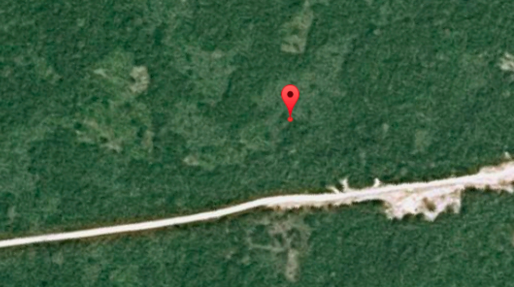
UAViators. He thus kindly gave me permission to share this footage with colleague Matt Shroyer so that we could explore the possibility of creating a mosaic and 3D model from the video. Incidentally, the image below is the highest resolution and most recent satellite image available of the camp on Google Maps. As you can tell, the satellite image is very much out of date.

Screen Shot 2015-08-14 at 10.56.08 AM

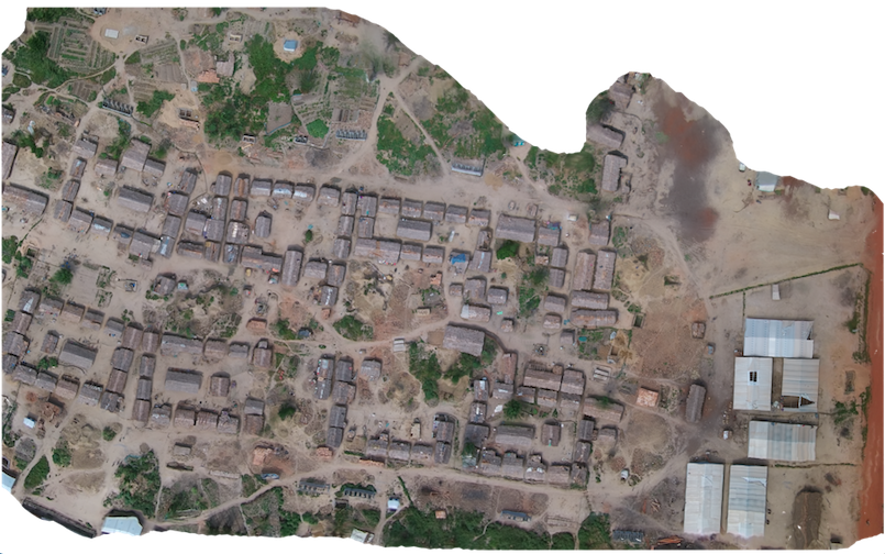
And here is the mosaic, which Matt kindly produced by taking hundreds of screenshots of the aerial video footage (click to enlarge):

Screen Shot 2015-08-14 at 11.00.01 AM

A close up:

Screen Shot 2015-08-14 at 11.02.13 AM

We then explored the possibility of creating a 3D model of the camp using the screenshots and SketchFab. The results are displayed below (click to enlarge). The numbers are annotations we added to provide relevant information on the camp. Perhaps in the future we’ll be able to add photographs & videos (captured from hand-held cameras) and other types of data to the 3D model.

Click here to view the 3D model, fly-throughs, and more. 

Read more…

78401_1_High.jpg

The Mobius docking station takes the ActionCam to a new level and makes it even more versatile. Now very easily you can enable it to transmit the live video to a receiving ground station via the docking stations built-in 5.8GHz 32ch 200mW mini transmitter. 

Slide your Mobius  camera into the docking station with video transmitter to make it compatible with popular video receivers as Fatshark and Skyzone. The transmitter has a range of about 1.5km / 0.9 mile and adds 30 grams to the total weight of your plane. The dock features a JST female connector for easy connection of the supply voltage (6-30V).

Mobius camera not included.

More details on the page at HobbyKing: http://hobbyking.com/hobbyking/store/uh_viewItem.asp?idProduct=78401&aff=5361

Read more…
3D Robotics

3689663022?profile=original

A very interesting paper entitled Rocking Drones with Intentional Sound Noise of Gyroscopic Sensors.  A MultiWii and APM drone were tested. One went down (see below for answer as to which):

Abstract

Sensing and actuation systems contain sensors to observe the environment and actuators to influence it. However, these sensors can be tricked by maliciously fabricated physical properties. In this paper, we investigated whether an adversary could incapacitate drones equipped with Micro-Electro-Mechanical Systems (MEMS) gyroscopes using intentional sound noise. While MEMS gyroscopes are known to have resonant frequencies that degrade their accuracy, it is not known whether this property can be exploited maliciously to disrupt the operation of drones. We first tested 15 kinds of MEMS gyroscopes against sound noise and discovered the resonant frequencies of seven MEMS gyroscopes by scanning the frequencies under 30 kHz using a consumer-grade speaker. The standard deviation of the resonant output from those gyroscopes was dozens of times larger than that of the normal output. After analyzing a target drone’s flight control system, we performed real-world experiments and a software simulation to verify the effect of the crafted gyroscope output. Our real-world experiments showed that in all 20 trials, one of two target drones equipped with vulnerable gyroscopes lost control and crashed shortly after we started our attack. A few interesting applications and countermeasures are discussed at the conclusion of this paper.

Answer:

3689663054?profile=original

Read more…

3689662905?profile=originalHello

I´d like to introduce my project of a smartphone based telemetry and navigation system called FlightZoomer.

Other than (almost?) any existing system FlightZoomer differentiates as follows:

  • There is one smartphone onboard the copter/plane (= the companion computer is the phone)
  • Another smartphone is used as glas-cockpit (groundstation)
  • Focus on realistic flight instruments, navigation systems and auto flight systems (modelled after the Boeing 787 cockpit). This means:
    --- Glas cockpit with PFD (Primary Flight Display) and ND (Navigation Display)
    --- Navigation database with fixes, radio beacons, airports, runways
    --- Radio navigation
    --- Instrument Landing System ILS
    --- Realistic Flight Management System for flight planning
  • Synthetic voice output for co-pilot simulation
  • Transmission 100% based on cellular networks
  • Supports (performance) flight test
  • The onboard smartphone is coupled to an APM based flight controller via MAVLink (over bluetooth)
  • Sensor data is fed to the groundstation primarily from the flight controller, though fallback modes to the phone's own sensors are also supported
  • Latency typically < 0.1s
  • No video or image stream (< this strongly reduces bandwidth and latency issues)
  • Communication between the airborne smartphone and the groundstation runs via a Relay Server
  • The Relay Server can run unattended as Windows desktop application at home
  • The solution is 100% software, all hardware comes off-the-shelf
  • The phone apps run on Windows phone


Project history

The project started two years ago and for the longest time focused on a standalone system that only relied on the phone´s sensors. This was the initial idea and I was able to make it fly though serious constraints remained (non consistent accuracy overall, unusable compass, strange attitude sometimes, GPS overall marginally).

Therefore I decided to mate the phone with the flight controller. So currently a prototype with an AUAV X2 is in flight test, and the results are amazing (compared to the standalone operation). That way I came in touch with the ardupilot community so consequently I also joined diydrones. So here in  that I can introduce FlightZoomer to you. I am also curious what would you think about FlightZoomer...

Next steps

While version 1.0 was the standalone system which was never released, I plan to release version 1.5 (with the MAVLink interface over bluetooth) in the coming months.

There are also a lot of ideas for further releases to improve the underlying premise (recreate the experience of dealing with "real" aircraft systems):

  • More voice features (e.g. extend the role of the virtual co-pilot, test flight director, maybe even ATC)
  • Recreate the autoflight modes of the 787 100%
  • Extend the features of the Flight Managment System
  • Maybe add additional cockpit hardware to the groundstation (modeled after a real cockpit)
  • 3D terrain

More information

click

(The flightzoomer website currently still covers version 1.0)

Personal background

I was educated as electronics engineer, studied Electrical Engineering and worked in professional software development ever since.

Some images

The onboard app:

3689662819?profile=originalThe groundstation:

3689662926?profile=original

The Flight Managment System (real 787 vs. FlightZoomer):

3689662875?profile=original

Read more…

"No Holes" GPS Mod

3689662793?profile=original

Here is my attempt to leave the lid completely alone without chopping or drilling. I have installed a Ublox 7N on a printed, hinged tower. Everything is attached with some 3M VHB. I moved the TELEM2 to the back, via Cloud Surfer mod. I inserted the GPS wires through the empty antenna hole and wired the plugs on the other side. The door is a 3D print of semi-clear PLA which is very bright when activated. 

3689662724?profile=original

Read more…

Nano Camera Quad

SKU271419-1.jpgSmaller and cheaper. This is the way technology tends to move. Cheerson, who made the wildly popular CX10 nano quad, has upped the fun by adding a camera! While it is only .3mp, its hard to argue the engineering prowess to pull this off on a commercial product. Coming in at less than $30 US, I think I will take a shot on this quad, if for no other reason than to marvel at how far consumer technology has come along.

Check out the details here.

Read more…

FOIA Request Reveals FAA UAS Enforcement Data

3689662599?profile=original

Back in April I filed a FOIA request with the FAA requesting the following documents:

“All releasable records related to civil enforcement actions or certificate actions against operators of unmanned aerial systems (UAS) or model aircraft, initiated in 2014 or 2015. This request includes, but is not limited to, letters of investigation, notices of penalty assessment, investigative reports, and other releasable documents, [and] a list of all incidents involving unmanned aerial systems or model aircraft that have been investigated by the FAA in 2014 or 2015 but are still pending or did not result in enforcement action, and all releasable documents related to those incidents.”

After several months of back of forth correspondence with the FAA's FOIA personnel requesting extensions of the response deadline, I finally received a response on August 13. While the FAA did not provide me with copies of actual enforcement action documents such as letters of investigation or notices of penalty assessment (I will follow up to see if any of those will be forthcoming), they did provide me with a list of all UAS related incidents/investigations thus far in 2015. The list contains 237 records from the FAA's National Program Tracking and Reporting System (NPTRS) and one record from the Accident / Incident Data System.

While I will leave it to professional journalists to conduct a more detailed analysis of the 237 records from the NPTRS system, here are a few interesting facts I gleaned from reading through the list:

  • The vast majority of incidents recorded are unsubstantiated reports of UAS sightings by pilots or home owners where the FAA was never able to conclusively prove that a UAS was flown in the area or identify the UAS operator. In at least a couple cases, the FAA concluded the object sighted was likely a weather balloon or party balloons. To me, this suggests that whatever regulations are ultimately passed, the FAA will have a very difficult time actually enforcing them.
  • Most other investigations resulted from complaints about unauthorized commercial UAS operations, and resulted in the FAA sending out their standard form letter advising the operator to apply for a Sec. 333 exemption.
  • Of the 237 records, only two appear to have resulted in new civil enforcement cases being filed:
    • The first was the infamous incident where a drunken government employee crashed a quadcopter on the White House lawn. While there appears to have been some disagreement between FAA officials as to whether an enforcement action was truly merited, the final decision appears to have been to file an enforcement case. A Letter of Investigation was sent on May 12 and the most recent update in that file, dated May 20, said, "Washington FSDO finishes enforcement package for Eastern Region based on the United States Secret Service report." I do not recall seeing it reported in the media that this incident actually resulted in an enforcement action by the FAA.
    • The second enforcement case concerns an incident that occurred on January 28, 2015 at Merrill Field in Anchorage, Alaska, where a quadcopter was flown too close to the airport and a helicopter on a training flight with an instructor and student on-board had to take evasive action. The local police tracked down the drone pilot and put the FAA in-touch with him. The drone operator was contrite and the incident appeared unintentional. While the local safety inspector considered education appropriate in this case, he appears to have been overruled by the legal department, which insisted on initiating a civil enforcement action. The current status of this case is unknown.
  • While no formal enforcement action appears to have resulted, a Letter of Investigation and a couple subpoenas were generated in the course of the FAA investigating a news report by WFAA News of Dallas, which aired a story on November 7, 2013 featuring Louisiana Hog Control operating a UAS to hunt feral hogs. The FAA subpoenaed and interviewed several reporters involved in producing the story.
  • The FAA received several complaints over animal rights groups flying UAS for their activism. Each of these investigations was closed when the safety officials concluded the animal rights groups were operating safely as model aircraft.
  • Several reports involve loss of control of military or border patrol UAVs.
  • In one record dated April 20, 2015, the Academy of Model Aeronautics (AMA) Government and Regulatory Affairs Office reported a pair of UAS operators who flew UAS over community events. That investigation was closed when the FAA talked to the two men who stated that they did not know the rules and promised not to fly over crowds again. I found this interesting since it appears on occasion the AMA is actively reporting UAS operators to the FAA.
  • The only record from the Accident/Incident Data System concerned an incident on November 15, 2014 when a UAS struck a person in the parking lot of the Bryant-Denny Football Stadium in Tuscaloosa, Alabama. No injuries were reported.

I am sure there are many more interesting things to be gleaned from these records, but those are the highlights I have noticed so far. Links to the PDF files on Dropbox of the documents I received can be found below.

FAA Response Letter

Responsive Documents

Read more…

Power System Reliability Considerations Part 2

Intro.jpg

F16 Aerobatic maneuver, Thunderbirds Aerobatic Team

This article is a follow-up on the previously presented results. We will examine the power system of a model airplane from the aspect of reliability. Common equipment configurations will be used as examples.

In a vehicle where the primary power source are electric batteries, the most crucial power consumers are the motor, the avionics and the servos. From now on, for the sake of simplicity, we will refer to the powerplant of the aircraft (which is tasked with producing thrust) as the “thrust” system, whereas the rest of the electric power consumers on the aircraft will be called the “control” system. We will carry out a high level analysis, since too much detail would eventually distract the reader from the most relevant factors.

Refer to Figure 1: our first layout consists of a single battery pack connected to the ESC. Control and thurst are powered by the ESC. Our working hypothesis is that the different failures modes can be considered independent.

figure1%2BLayout%2B1.png

Figure 1. Single battery system

Let's select the battery pack reliability value at \(R_p=0.96\) and the reliability value of the ESC at \(R_{ESC}=0.98\). The battery and the ESC should be working at the same time, so for the first layout, the reliability is \(R_{l1}=R_p \cdot R_{ESC}=0.940\). We notice that the overall reliability is lower than the reliability values of each single component. Moreover, our system is not redundant, since the failure of each component causes the failure of the overall system.

Our second layout consists of two independent batteries, one for thrust and one for control. One battery is physically connected to the motor's ESC and the other is connected to a BEC circuit that supplies the control module. Usually, the power related to the thrust system has more capacity and nominal voltage than the control battery.

figure2%2BLayout%2B2.png

Figure 2. One battery for thrust, one battery for control

Let's set the reliability value of the battery packs to \(R_p=R_c=0.96\), the reliability value of the ESC to \(R_{ESC}=0.98\) and the reliability of the BEC to \(R_{BEC}=0.98\).

Under nominal system operation, the two batteries, the ESC and the BEC should be operational at the same time. From this aspect, the reliability of the second layout is \(R_{l2}=R_p\cdot R_{ESC}\cdot R_c\cdot R_{BEC}=0.885\). At first, this result seems wrong: Despite having used more equipment, the overall reliability is now lower than the initial 0.940 value from Layout 1. Until now we haven't considered in detail what happens when a part of our system fails and that led us to non-comparable results. In fact, under careful examination, the second layout has extended capabilities. In layout 1 we have a probability \(1-R_{l1}=0.06=6\%\) of a total power loss, and if this unfortunate event happens then we will lose control of the vehicle as well as any ability to safely (crash) land the unit. Revisiting layout 2, we calculate the probability to lose completely the vehicle control. The cases that lead to a catastrophic failure are those that include a simultaneous failure of both the batteries or both the ESC and BEC. The following table presents all such failure cases.

Case #

Battery P

 Battery C

 ESC

 BEC

1

fail

fail

fail

fail

2

fail

fail

ok

fail

3

fail

fail

fail

ok

4

fail

fail

ok

ok

5

fail

fail

fail

fail

6

ok

fail

fail

fail

7

fail

ok

fail

fail

8

ok

ok

fail

fail

Table 1. Failure modes that lead to total power loss equivalent to Layout 1

Combining the probabilities of the cases indicated in the table, we get the following expression for reliability \(R_{l2flat}=1-((1-R_p)\cdot(1-R_c)+(1-R_{ESC})\cdot(1-R_{BEC}))=1-(0.0016+0.0004)=0.998=99.8\%\). Now the odds changed to being favorable to Layout 2. However from a user's point of view, it is more interesting to know the value of the probability that the vehicle is still controllable (at least to some degree) after a failure. The necessary condition for controllability is that the BEC and its battery are still working properly.

Refer to the next table. In cases 9 to 12 the pilot will have a chance to land the aircraft safely.

Case #

Battery P 

Battery C 

ESC 

BEC

9

fail

ok

fail

ok

10

ok

ok

fail

ok

11

fail

ok

ok

ok

12

ok

ok

ok

ok

Table 2. Failure modes that lead to a controllable (crash) land.

The reliability related to this minimum guaranteed performance is \(R_{l2user}=R_c\cdot R_{BEC}=0.940\). This value is the same as the value of the first layout. With this method of analysis, the advantage of layout 2 over layout 1 not so clear anymore. However, the situation can be radically different if there is a relationship between the reliability of batteries/ESC/BEC and the corresponding capacity/max-current/etc or there is a dependency among the reliabilities of single items.

All things said, however, by inspection of layout 2, it is evident that it does not offer any physical redundancy, so statistics apart, it's wise to not expect any sudden reliability increase.

figure3%2BLayout%2B3.png

Figure 3. One battery for thrust, dual batteries for control

In this layout number 3, we have a battery that goes straight to the ESC and a redundant voltage regulator, powered by two separated batteries, which feed the control system. The working hypothesis is that the redundant voltage regulator will continue to work even if one battery fails. The most tricky failure to handle for the voltage regulator is a battery cell short. Fortunately even regulators at RC grade can handle this condition [1].

Back to the math, this layout is more reliable as the system composed by voltage regulator with \(R_v=0.98\) and two batteries with \(R_c=0.96\).

\(R_{l3}=1-((1-R_c\cdot R_v)(1-R_c\cdot R_v))=1-0.0035=0.996=99,6\%\) [2]

Using the same battery pack type, layout 3 offers augmented reliability, and that result was reached by means of physical components redundancy.

Typically, the weakest link in the chain affects the system reliability the most, so prior to purchasing or building an expensive or complex reliable thrust system, an analysis of the reliability of the whole aircraft system should be performed. It will be useless to have an amazing thrust system with undersized servos.

References

[1]

For example

Smart-Fly - PowerSystem Eq6 Turbo Plus- Battery input protected

[2]

Mc Dowall (2005), Lies Damned Lies and Statistics: The Statistical treatment of Battery Failures , Retrieved 09/07/2015

Read more…

Brief Survey on ADS-B and Small Drones

3689662693?profile=original

I've got a brief 10-question survey which seeks to get your opinions about ADS-B solutions for small drones.

The technology for tracking small unmanned aircraft systems (UAS) has advanced rapidly in the past few years.  New and disparate solutions all claim great promise.  Many of these solutions are based on automatic dependent surveillance-broadcast (ADS–B), a cooperative surveillance technology in which an aircraft determines its position via satellite navigation and periodically broadcasts it, enabling it to be tracked by ground control station. ADS-B signals can also be received by other aircraft to provide situational awareness and allow self-separation.

But is it the right solution for small UAS (under 55 lbs.) operating in low-altitude class G airspace?

When its done I'll post the results back here in a new post.  Thanks much! - Colin

Take survey here: https://www.surveymonkey.com/r/DBRH89H

Read more…

Iris+Solo=Sirus

3689662655?profile=original

After months of waiting to win a Solo in the giveaway, I just made my own. The angled arms are shorter with the back arms swept back to accommodate 10" propellers. The landing gear was brought in to a mount on the underside (which can still mount a Tarot gimbal) Detachable legs that work as replacements for the !ris+ legs were integrated into the mount. A mount was created for the front mount for the Tarot 2D to get absolutely zero encroachment of legs/props. A tower mounted Ublox 7N was added to match the Solo. These are, of course, 3D printed parts. I hot knifed the threaded inserts from broken Iris arms and all in all was mostly design and print. 3 months of work done.

3689662577?profile=original3689662669?profile=original3689662641?profile=original

Read more…

5 Tips on Finding a Good Drone Attorney

3689662616?profile=original

By Jonathan Rupprecht, Esq. writing for Drone Analyst

In response to the rapidly growing drone industry, there are now many attorneys and law firms that are seeing an opportunity to make money and are offering drone legal services as a part of their regular practice areas.  Although many of these attorneys and/or firms may have experience in their regular and specific legal fields, they most likely are just trying to get into this new legal field area (“get their feet wet”) by offering a new drone practice group with drone legal services. How can you find an experienced drone attorney that will best serve your drone legal needs as opposed to an attorney who is just trying to dabble in the drone area? Here are five tips to find an attorney to best help with your needs:

1. Find out how many 333 petitions the attorney has filed.

Many attorneys are starting to come into this new legal field. Some of those attorneys have no aviation law knowledge or section 333 experience. If they don’t have any experience, this could cause some problems.  One example is where an inexperienced attorney might charge you more for a petition so they can learn how to do it or to get experience. Another example is that an inexperienced attorney might not be able to rapidly file your 333 petition which means your wait is longer until you can commercially operate.

Read more here:  http://droneanalyst.com/2015/08/11/5-tips-on-finding-a-good-drone-attorney/

Read more…

3689662558?profile=original

In June 2014, a joint USAID and USGS team used a small UAV to map artisanal diamond mining sites in Western Guinea. The purpose of this UAV mission was to support the “Kimberley Process (KP), an international initiative aimed at preventing the flow of conflict diamonds.” Adhering to the Process’s regulations is proving challenging for “countries whose diamonds are produced through artisanal and small-scale mining (ASM).” These mines are “often remote and spread over vast territories, and the diamonds found are frequently sold into informal networks,” which makes it “very difficult to track production—a key requirement of the KP.” National governments have recently taken important steps to formalize ASM by “registering miners, delineating mining zones, and establishing a legal flow chain through which production is intended to move. The ability to map and monitor artisanal diamond mining sites is a necessary step towards achieving formalization. Doing so helps to identify where mining is taking place, the extent of activities, the amount of production, and how the activity and production change over time.”

Screen Shot 2015-08-05 at 4.18.30 PM

While the US Geological Survey (USGS) has been using satellite imagery to “identify ASM activities and estimate the production in diamond mining zones through-out the region,” satellite imagery presents a number of limitations. These include “atmospheric constraints (cloud cover, haze, smoke, etc.)” as well as “temporal resolutions that fail to capture the dynamic nature of ASM sites and spatial resolutions that can be inadequate for identifying fine-scale features.” Hence the use of UAVs to “support USAID’s Property Rights and Artisanal Diamond Development (PRADD) project’s efforts to formalize ASM in Guinea.” USAID and USGS deployed a joint team in June 2014 to “create detailed site maps and generate very-high resolution digital elevation models (DEMs) of the region to better inform diamond production evaluations.” The team flew a DJI Phantom 1, a multi-rotor UAV (pictured below) to “collect data at seven artisanal diamond mining sites in the Forecariah Prefecture of western Guinea.”  The DJI UAV was flown by Visual Line of Site (VLOS).

Click here to continue reading

Read more…

711 Materials measures Waterford Plant

In a related project with my other company Jim Oliver Designer, I was tasked to measure the aggregate and sand piles at 711 Materials. JOD contracted the job of redesigning 711’s website and during the initial meeting I could not help but to mention UAV’s and the services available. The owner was quite interested being that he has 12 plants and plans to scout other quarries; plus his son is apparently an insane model helicopter pilot. Here is a Pix4D animation of the project. This was for 711’s plant in Waterford, CA.

Read more…