All Posts (11086)

Sort by

The A B C of laser altimeters

3689619289?profile=original

The SF10 family of laser altimeters was designed by people on this forum. Requests for new features and numerous emails about performance and applications has lead to the development of a compact, light weight, rugged design that can be used in many UAV applications.

We've produce three different versions, each with the same features but having different measuring ranges and representing three broad categories of application - close to the ground, intermediate flight operations and maximum legal altitude. The picture below gives an idea of where we see the different products being used:

3689619232?profile=original

We've matched the cost of available technology to the different operating requirements of small and medium scale UAVs, and the table below shows how we've managed the trade-off between price and performance:

                  Model           Laser                         Detector                          Maximum range          Price

                 SF10/C      High power         High performance APD             >120m                      High

                 SF10/B      High power               Standard APD                       >55m                       Medium

                 SF10/A      Low power                Standard APD                       >25m                        Low

In all models of the SF10 we've kept the energy of the laser pulses very low, making them Class1M - safe for human eyes, and because we believe in high reliability, all models have narrow band optical filters to cut out background sunlight.

Other standard features on all models include:

  • USB port for entering configuration settings
  • I2C bus with configurable address
  • Serial port with configurable baud rate
  • Analog output with configurable ranges
  • Offset trim to match airframe

The team at LightWare would like to thank the hundreds of customers who have contributed to our ongoing effort to improve laser technology for UAS applications. We're having fun, I hope you are too!

L.D.

Read more…

Rover - Ground based Inspiration

Having a new project starting and knowing it was going to be ground based I have had to try and sike my self up a bit. Personally seeing the multirotor platform as the phenom when considering what you can do with remote piloted craft, especially with Arducopter. I started searching for the proper inspiration. One time I had a remote controlled gas powered kyoshyo blizzard and when this video appeared well, it gave me with what I was searching.

Looking forward to playing "Rover"

Read more…
3D Robotics

Commercial Drone Regulations: Canada vs the US

Flags-of-usa-and-canada.jpg?width=400

From Robohub:

When Canadians attempt to characterize aspects of Canadian culture, it’s not uncommon to draw comparisons with the US. I recently noticed that as I respond to questions about the Canadian regulations surrounding commercial drones, I often begin by stating that our regulatory framework is quite distinct from that of the US – here’s why…

In Canada, commercial operators can apply to obtain Special Flight Operations Certificates (SFOCs) from Transport Canada. It takes Transport Canada about 20 days to assess applications, and last year the agency issued 945 SFOCs to applicants representing a variety of industries including aerial videography, agriculture and oil and gas.

Generally, the Canadian regulations do not establish bright line rules governing drone operations – for instance they do not specify whether you need a pilot’s license to complete a commercial drone flight, or whether it is permitted to fly beyond the visual line of sight. Rather, Transport Canada assesses applications using a case-by-case approach. In order to obtain approval, applicants must show that they can mitigate operational risks to an acceptable level.

In the US, the Federal Aviation Administration (FAA) has been working to develop drone regulations since the enactment of the FAA Modernization Act of 2012. Until the framework is in place, those looking to fly for commercial purposes can only proceed by exemption. Most companies have been denied exemptions, the notable exceptions being a couple of oil companies that received approval to operate drones in remote areas of Alaska.

Last Thursday, the FAA extended regulatory exemptions to six Hollywood companies looking to film using drones. Although the Hollywood exemptions represent a move in a positive direction, the restrictions placed on the companies are quite onerous, for instance the operations must take place in a controlled closed-set environment and may only be completed below 400 feet and within the visual line of sight.

By comparison, commercial drone operations are the norm in Canada and will continue to be an exception in the US until the new rules are in place.

Read more…

Part Two: Here is the original picture of the finished product:

3689618661?profile=original

This is the second part of a 2-part series on 'How to build a High-Definition FPV UAV using a Raspberry PI with HD camera, using a high speed WiFi link.

In my first post on the subject (located here), I discussed the parts I used, and how to install them into a Hobby King Go-Discover FPV model. 

In this post, I will discuss installing the Raspberry PI and the PI camera in the Go-Discover gimbals, and the software configuration for both the Raspberry PI and the ground station PC.

From the previous post, step 3 was completed by installing the Ubiquity Rocket M5 in the model.  Now onto step 4:

Step 4: Install the Raspberry PI and PI Camera

Here is a photo of the position of the PI in the Go-Discover model:

3689618887?profile=original

The PI fits nicely just behind the camera gimbals, with the USB and HDMI ports on top. In the right side you can see the Cat5 network cable attached. This cable connects to the ethernet switch, which is also connected to the Rocket M5 input port.  

The two cables shown on top are the servo control wires for the gimbals, which I have directly connected to channel 4 and 5 on my radio.  I am using channel 4 (normally the rudder stick on my radio. Since there is no rudder on a flying wing, this is a convenient channel to use to move left and right with the camera. I have not (yet) moved to a head tracker, but if you already have that setup, just assign the channels accordingly.

To install the PI camera, remove the stock plate from the gimbals (for a GoPro), and mount the PI camera as shown in this photo:

3689618926?profile=original

The PI camera case fits very nicely into the slot, and again I used a small piece of velcro to hold it down. You could use a couple of small screws instead if you want a more secure hold.  The two gimbals servos are also shown here. They are simple to install, just follow the Go-Discover instructions.

Here is a front view of the PI camera installed:

3689618962?profile=original

Here is the block diagram describing all the connections:

3689618829?profile=original

Some comments on my previous post suggested that it is possible to eliminate the ethernet switch and serial-to-ethernet converter using the Raspberry PI and a serial port on the PI. I believe this post describes how to talk to the PI via the NavLink, but in this case, I want to use the PI to bridge the connection from the ground station to the APM/PixHawk. Somebody please comment on this if you know more about it.   I believe it would require a TCP/IP to serial link from the PI to the telemetry port on the APM, and some software on the PI to act as the bridge.  The main connection to the ground station is via the Rocket M5 and TCP/IP, not through a telemetry link (900 Mhz or Zigbee like I used on my other models).

Step 5: Getting it all to work with software configuration (the really fun part starts now).

Check out this post on what others have done with streaming and the PI.  My experiments showed that using GStreamer on both the PI and on Windows gives really good results with very low latency, if you use the right parameters. 

Get GStreamer on the PI by following this blog.   This is the same version of GStreamer that I am using on my setup. 

Make sure your PI camera works ok by plugging in the PI to a standard monitor using the HDMI port and follow the instructions on the Raspberry PI website on how to get the camera up and running (without GStreamer).  Once you have a working PI and camera, you can then proceed to stream things over the network.  

Note: It is suggested that you first get the PI streaming video by plugging it directly into your local network where you can also connect your ground station PC with the correct IP addresses (without the Rocket M5).   For my PI, I picked 192.168.1.2,  and for the ground station, 192.168.1.1.    Make sure you can ping the PI from your PC and the PC from the PI.  

For streaming, you will also have to make sure all the ports you intent to use are open on the firewall (described later).

For the ground station PC,  you can download GStreamer here.  Make sure when you install, select to install everything , or full installation (not the default). 

Here is the command I use for the PI to pipe the camera output to GStreamer:

raspivid -t 0 -w 1280 -h 720 -fps 30 -b 1700000 -o - | gst-launch1.0 -v fdsrc ! h264parse config-interval=1 ! rtph264pay ! udpsink host = 192.168.1.1 port= 9000

The command is explained as follows:

raspivid is the command to start the camera capture on the PI.  The -w switch is for the width in pixels, and the -h switch is for the height.  In this case, I am using 1280 X 720, but you can try any combination that fits your needs. 

The -b switch is the bit rate for the sampling. In this case I chose 1.7mbs to send over the stream. Again you can experiment with higher or lower values. This settings seems to work good for me, and the latency is almost unnoticeable.  

the "-o - |" is piping the output to gstreamer.  Make sure you include the dash before the pipe "|" symbol. 

For the GStreamer command, all the filters are separated with an exclamation point "!", as these are individual drivers that are part of GStreamer.  Since the PI has hardware accelerated video, the output is in a format called "H264", which is a highly-compressed stream. The GStreamer filters are configured to transport the output via a UDP socket connection to the target PC. Notice the 'udpsink' element which specifies the host - in this case your ground station, and the UDP port.  I am using port 9000, but you can use any open port on your system, but be sure to open the firewall or it won't work!  You can also use TCP instead of UDP, but for such a data stream, I chose to use UDP since dropouts are certainly possible, and with UDP this is ok, but with TCP, you could have socket problems and higher latency. 

Note: to get the PI to execute this command on boot, make a shell script with the above command and add it to your local.rc boot sequence. That way when the PI boots, you get the stream without having to log into the PI remotely. 

For the ground station PC, once you have installed GStreamer and opened the correct ports, use this command (from the command prompt) to view the stream:

c:\gstreamer\1.0\x86_64\bin\gst-launch-1.0 udpsrc port=9000 ! application/x-rtp,encoding-name=H264,payload=96 ! rtph264depay ! avdec_h264 ! videoconvert ! autovideosink

If all goes well, you should see the PI camera output on your PC screen in a popup window.  For those of you what want to use FPV goggles, you can connect to the HDMI port on your PC to display the output if your goggles support HDMI. 

I have this command in a batch file (with a PAUSE) statement at the end to keep the window open.

WHEW!  If you got this far, you are amazing. 

The last step to complete the build is to connect to the APM from mission planner.  The method I used to connect was to install a utility that converts a TCP connection to a virtual serial port, but I also think that directly connecting the mission planner to the TCP port will also work, however I have not tried it. I will post back later after trying it.

Here is the link to setup the serial to ethernet device to have an IP address and port.

Here is the link to the configuration utility for installing the virtual serial port.   

Once you have a serial connection over TCP/IP working to the APM, you should be able to connect with Mission Planner. On the maiden flight, it worked perfectly, and I didn't see a single drop in the telemetry data or anything noticeable in the video transmission, however my first flight was limited to 2km.

The last step is to connect the Rocket M5 to the Nano M5 and test everything using the OTA (over the air) connection. If all is well, you are ready to fly!  But be careful on your maiden, you just spent $700. 

Finally, here is a photo of my Antenna Tracker with the Nano M5 attached. My next update will include a video of a longer flight.  

3689618942?profile=original

Happy Flying!

Read more…

GoPro 4 is Here - Sort of!

GoPro is finally announcing the new 4 Silver and Black:

3689618849?profile=original

It , of course has the new 30fps 4K and - not surprisingly costs $100.00 more than the last one so now $499.00.

Probably using the new Ambarella 9 chip, but no mention made of built in electronic image stabilization which is a feature of the Ambarella 9 chip. 

http://www.ambarella.com/uploads/docs/A9%20Product%20Brief%20120813-2.pdf

The new Silver is also $100.00 more and has the nifty built in color touch screen.

3689618980?profile=original

Nice, but not earth shaking and a bit disappointing.

Why no stabilization (My Sony AS100V does remarkably well even on a quad with no gimbal) and why didn't they include the touch screen on the Black, you'd have thought they could have afforded it.

Sadly seems more notable for what they didn't do than what they did.

Still 4K at 30fps is more important than ever and that will certainly drive "pro" sales.

Here is the GoPro site: http://shop.gopro.com/cameras

The reason I said "sort of" is that the announcement says coming soon.

Our local hobby shop has been told they can start selling on October 5th.

Best Regards,

Gary

Read more…

After 3 months of research, picking a platform, and building my own HD FPV rig, I decided to write this blog to share my experience. I have been flying FPV for about a year now, and this was the most fun project yet! 

Here is a picture of the finished product:

3689618661?profile=originalThe platform I picked was the Hobby King 'Go Discover' FPV flying wing. There are many other possible platforms, but to accomplish my goal of creating an HD platform, this bird had the space and wing loading that would accommodate the components. I like the flying wing platform because of the simplicity of the servo setup - only two channels needed for flight. This made it possible for me to use a 6 channel radio and receiver. The Go Discover also has the camera gimbals for changing the viewing perspective in flight, and since I picked  flying wing, I had enough channels left to control the gimbals and the ArduPilot flight modes with a 6 channel radio. My previous FPV plane was the Phantom FPV (also from Hobby King), but its camera space is limited and there was not enough room in the main fuselage to fit all the electronics. The Go Discover turned out to be just right for everything to fit, but with nearly no room to spare. The final rig weighed in at 4.5 lbs, using a 4000mAH 4 cell lipo. 

The final cost was around $700, (not including the antenna tracker, and WiFi receiver), but for full HD, this was not too bad in my opinion, since some HD systems cost this much without the plane and other electronics.

Parts List:

Go Discover Kit ($118)

You can save money by using the PNF version, however I chose to build my own and choose the motor/ESC/receiver combination.

For the motor I picked this 700kv Outrunner ($36) It barely fits, so don't go bigger.

A Turnigy Plush 60amp ESC ($35)

A 4000mAH 4 Cell Lipo ($37)

ArduPilot APM2.6 with GPS ($74)

Ethernet Switch Module ($16.50)

You will need the Ethernet Switch if you want telemetry over the same WiFi connection you will use for the video. To accomplish this, you will need a 'Serial-to-Ethernet converter', which can be purchased here:

Serial-to-Ethernet converter for APM Telemetry over TCP/IP ($22)

Power Supply for Raspberry PI ($7) (Optional if you want to power everything from the main battery).

1000 mAH battery to power the PI and ethernet switch ($11) (Optional if main battery used to power everything)

Raspberry PI with Case ($40)

PI Camera ($25)

Rocket M5 WiFi 5GHZ ($89) Note: you will need to also buy an access point (Nano M5 is here)

I am using the Nano M5 as the access point and an antenna tracker that I built. See my post here on how to build the tracker, or buy your own.

5.8 GHz Planar Wheel RHCP Antennas, you need 2 for MIMO connection using the Rocket M5 ($90) Less expensive antennas may work, but I have good results with these.

6 Channel 2.4 GHz receiver ($13) (Your choice of radio/receiver combo, my radio is a Turnigy 9xR)

2 Digital Servos for the wings ($40) I don't like to skimp on these. These are very good servos.

2 Analog Servos for the Gimbals ($10)

3, 1 Ft, ethernet cables ($7) (One for PI, one for Rocket M5, and One for Serial-to-Ethernet for Telemetry)

Power-over-ethernet cable for the rocket M5 ($5).  You can buy these at any electronics outlet or google it.

Misc RF connectors (Right angle SMA, and a short RG59 cable with SMA) ($10).

Total for Plane: $671.  + Ground station access point ($89),  $760.  I am not including the cost of the antenna tracker, but from my blog, you can build one for about $250.  The grand total should be under $1K, not including your ground station, but I assume you already have one.

Now for the fun part - assembly. I will describe my assembly for the Go Discover, but the process will be similar for any platform you choose. You will need to arrange the parts as you can to get everything in, and also achieve the correct CG. It took a bit of 'trial and error' for me to find the correct combination.

Step 1: Install the motor and ESC.

I chose to build from the back forward, installing the motor, ESC, then battery/electronics, then finally the Raspberry PI and camera. 

From other blogs about the Go Discover, the motor mount is very weak, so I chose to 'beef' it up by adding some EPO foam and epoxying a metal mount designed to support the SK3 motor. Here is a photo of my setup with the ESC and motor mounted in the rear:

3689618676?profile=original

Notice the area just in front of the motor mount where I added some extra foam to fill the space that exists in the stock model. I used some old EPO foam from a junk model and glued it into place. The ESC fits nicely right behind the battery. The battery is installed using Velcro to hold it in place. 

Unfortunately, the amount of electronics that exist in this space made it difficult to just swap the battery, but I could not find a way around it, so I leave the battery in place and charge it in the plane. Of course this limits the number of flights per day, but for such an advanced toy, it's a trade off.

Step 2: Install the ArduPilot, GPS and Serial-to-Ethernet converter.

In the middle section, there is a trapezoid-shaped area that I decided to use to mount the Ardupilot, GPS and Serial converter. Here is a picture of the installation:

3689618762?profile=original

In the trapezoid area, I cut out some cardboard that matches the shape, and placed it over the battery. I then mounted the 3 components on top of the cardboard cutout. The view of this photo is with the tail of the plane on the top. On the right side of the plane is the GPS module (with some duct-tape holding it in place). It's the purple square-shaped PCB. I used Velcro under the unit also, and for all the other components. 

In the center is the Serial-to-Ethernet converter. To connect it to the Ardupilot, you will need to modify the connector that is normally used to connect to the Telemetry port with the 900mhz transceiver that you can buy from 3-d robotics. There are 4 wires: ground, power, rx an tx.  You can find a schematic here.  I will explain later how to make this work with your PC software (download from the internet). The Serial-to-ethernet converter has the pinout silk-screened on the PCB and it's pretty obvious were to connect the wires. Make sure you connect TX to RX and RX to TX from the converter and the Telemetry port on the Ardupilot. 

Allow the pins of the serial converter to hang over the cardboard so you can plug in the connector, and velcro the unit to the cardboard. 

Finally, on the left side, you can mount the ardupilot.  Connect as usual to the GPS port, and radio. Please refer to the Ardupilot website on how to configure an connect your Ardupilot. I will not cover that portion here. 

Step 3: Install the Ethernet Switch,  Rocket M5 and antennas:

There is a bit of work to do here because the Rocket M5 comes in a big (sealed) plastic case. You MUST cut it out of its case, and you WILL void the warranty. Use a dremmel tool and CAREFULLY cut around the edge of the case (not across the top), and remove it from the plastic case.

It is highly suggested that you get the Rocket M5 and Nano M5 talking to each other BEFORE you install the M5 in the model. Follow the instructions on the Ubiquity website on how to do this. It's basically the same as connecting two WiFi terminals. Each unit has a built-in webpage for configuration. Configure your Nano as an "Access Point" and the Rocket as a client.  You should be able to "ping" both units from your PC and connect the Raspberry PI to the network and ping it also. For my Raspberry PI, I set the IP address of the ethernet port to 192.168.1.2, and the ground station PC address to 192.168.1.1.  You will also need to set the IP address of the Rocket M5 and the Nano M5 when you configure them. 

Here is a photo of the position of the Rocket M5 installed in the plane after removal from the case:

3689618723?profile=original

Note: this view is the front of the model pointing to the right. The ethernet switch is mounted just in front of the trapezoid cutout that was used to mount the ArduPilot. It is mounted with the PCB vertical in the fuselage. Notice the Ethernet cables connected to it in the left side of the above photo. Again, I used Velcro to mount the ethernet switch.  Notice the gray cable. This is the POE (Power over Ethernet) cable that you will need to use to power the M5. You can get one of these on EBay or Amazon.

There are TWO RF connectors (left side of plane) on the Rocket M5 because this is a MIMO setup (Multiple Input, Multiple Output), which is the same technology used in LTE phone networks. The two antenna configuration gives this radio higher throughput, more range, and better SNR, all of which makes this setup work very well.

You should mount the antennas apart from each other, and for my setup I decided to place them on either side of the plane just under the wing. Since the Go Discover has a pretty big fuselage, the antennas don't touch the ground and are cleared by a couple of inches, so unless you go nose down on landing, they should be safe.  Notice the RF connector on the top of the photo. This is the 2nd antenna. The first antenna is mounted directly below the first RF connector on the left side of the plane.

Also, not shown in this picture is the 2nd battery (1000 mAH) and the control receiver, that are mounted under the Rocket M5. The power supply for the Raspberry PI is also mounted in this space, just behind the Rocket M5. 

Note: to hold the Rocket M5, I created a couple of EPO foam mounts to make sure it didn't move, and glued them in place under the M5, and then I used Velcro to hold it down. 

Here is a photo of where I installed the antennas:

3689618790?profile=original

Notice the two white posts on either side. These are the 5GHz planar wheel antennas. 

Here is another set of photos showing the RF connectors:

3689618748?profile=original

3689618692?profile=original

Notice also in the above photo, on the left side is the radio receiver (Orange RX DSMX type for my radio). Out of view (under the M5) is the power supply used to power the Raspberry PI. You can mount this anywhere, but this is a convenient spot.  The placement of the radio is also convenient to connect the servo wires to the ArduPilot.

Step 4: Installing the Raspberry PI and Camera

(More to come)

Read more…

VT330--Landing-Gear.png?width=700

3689618491?profile=original

I have not picked this Vtail up since I was stupid enough to take a part of a tail rotor to the eye this past June. It was a really stupid mistake, everything is fine now and it confirmed that the original landing gear would not work, at least for me. The above gear shown is from a mold that is then cut on a water-jet. I made up several sets for many of the models I wanted to covert to coaxial setups, and could not forget the Vtail. 

This frame will convert well to a Mini Y6 design also and if I flip the gear around everything clears. This curve shape was more of opportunistic engineering than anything else, once cut though it has proven to be great landing gear. 

Read more…
3D Robotics

ArduIMU V4 on Kickstarter

Seven Five years after this community created the ArduIMU V2 (and later V3) project, it's back with a much improved version on Kickstarter, with wireless, the latest sensors and processors, datalogging and more! (The Kickstarter project has their chronology a bit wrong; 3DR didn't exist in 2007, and this project started as a private project by Jordi Munoz and Jose Julio. In 2009 it became ArduIMU V2 and V3 under a DIY Drones banner). 

Initially, the ArduIMU project was started as an open source project by 3DRobotics in 2007 to create an inertial measurement unit based on the Arduino™. We contributed to the software development of that project, but, the initial ArduIMU was meant to be used solely as an inertial measurement unit. We want to do better than that; so we developed a brand new platform with other sensors such as a barometer, relative humidity sensor, and light sensor. We also included wireless communication capabilities as well an SD card for data logging and storage. Since then, we have gone through many revisions, adding even more sensors and functions which are present in the latest ArduIMU V4. With this new augmented and improved sensor board we are redefining the term IMU. We proudly present our Arduino™ based Integrated Measurement Unit: the ArduIMU V4.

ArduIMU V4 Final PrototypeArduIMU V4 Final Prototype

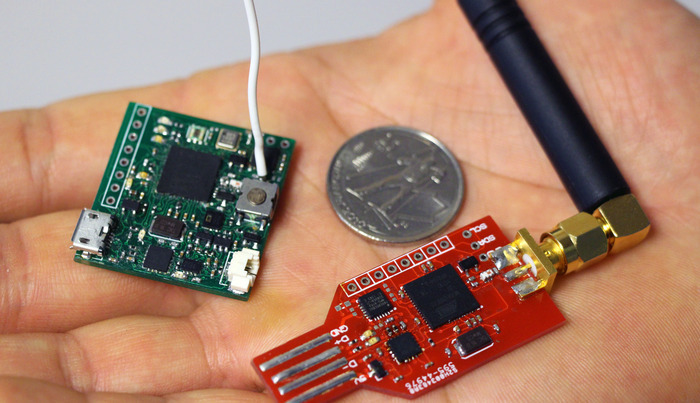
Our team squeezed a huge amount of functionality and sensors into a tiny form factor: π cm x π cm (a 3.14 cm x 3.14 cm square PCB). It can fit into a small plastic case as shown in the video.

Several people from the open source community have joined in and helped us develop the hardware and the software for the ArduIMU V4. The ArduIMU V4 went through various development phases starting with multiple discrete sensors up to the latest and best (and most cost-effective) integrated inertial measurement chips. We have designed the hardware from the ground up to provide functionality never before seen on these devices.

ArduIMU V4 IterationsArduIMU V4 Iterations

The ArduIMU V4 is not just useful to applications which require inertial measurement, but has evolved into a powerful and versatile hardware framework for hobbyists, makers and hackers. After using it first-hand, we believe that the ArduIMU V4 is a must have for Arduino enthusiasts, developers, hackers and tinkerers.

So, what's actually on the ArduIMU V4?

The ArduIMU V4 is based on an ATmega128RFA1 and is 100% compatible with theArduino Framework.

What's on the new ArduIMU V4?What's on the new ArduIMU V4?

Of course, we included an FTDI chip (USB UART, FT230XQ) on the ArduIMU V4 board so the communication with the host computer can be done easily and directly from the board using the attached micro USB connector. We've also done the hard work for you and included a lithium battery fuel gauge (charging state), and charging circuitry right on the ArduIMU V4 PCB, all you have to do is connect your ArduIMU V4 to the host computer (or other regulated 5V external power supply) and presto! it charges for you. Since we can't predict your unique requirements, we leave it up to you to pick a battery with appropriate size and capacity.

What can you use it for?

The ArduIMU V4 gives you access to SPI, I2C, UART (UART0 & 1) (UART1 is broken out as a GPS connector port), analog input and PWM output. This will allow developers to take their own ideas and design and develop custom shields for the ArduIMU V4.

And it doesn't stop there! We were able to compile the Contiki OS on the ArduIMU V4 and use it for various projects, including implementing 6LoWPAN for a network of multiple ArduIMU V4 units. Welcome to the Internet of Things!

ArduIMU V4 Connectors (top view)ArduIMU V4 Connectors (top view)
ArduIMU V4 with mounting holes (bottom view)ArduIMU V4 with mounting holes (bottom view)
Here's a handful of cool ways you can use the ArduIMU V4:

  • Learn to use sensors 
  • Transmit data. Even more fun, transmit data wirelessly! 
  • Make a wireless mesh networks with multiple nodes 
  • Sense motion (e.g., sports, walking, running, flying, ...) 
  • Use it as a humidity sensor (e.g. to check if a pipe is broken in your basement)
  • Log internal and external sensor data 
  • Blink the onboard LEDs 
  • Detect light using the light sensor, it's even capable of monitoring your vitals using pulse oximetry! 
  • Monitor the health of plants with the various humidity and temperature sensors 
  • Use it to help run your quad-copter 
  • Track weather changes 
  • Monitor analog data input and send it off somewhere wirelessly. 
  • Craft a PWM signal to help control a motor. 
  • Use it as an powerful inertial measurement device 
  • Learn Contiki OS and get involved with the Internet of Things 

How do I communicate with the ArduIMU V4?

ArduIMU V4 has a built in Micro-USB port for charging and communication with a host computer. Since we used a standard FTDI USB-Serial chip, you don't have to worry about finding finicky drivers to make it work. To communicate wirelessly, you simply use two ArduIMU V4 units and set up wireless communication between them. Of course, the ArduIMU V4 can do both at the same time, so you could have one ArduIMU V4 out sampling data and sending it wirelessly to a second ArduIMU V4 that is plugged into your computer's USB port to do some heavy number-crunching.

Existing ZigBee devices can also be used to communicate with the ArduIMU V4. However, while this feature is supported in hardware, we are still working on an easy to use Arduino-style framework to make this feature more accessible to those with little micro-controller development experience.

We have also designed an ArduIMU V4 compatible receiver based on the same microprocessor. Besides receiving wireless data from an ArduIMU V4, it also includes the 9-axis motion tracking device and can plug directly into your computer's USB port. The most important feature of the receiver is the SMA port, which allows you to boost your signal range or directivity with a compatible antenna. We are not making the receivers in large quantities yet, but are willing to add it if there is enough interest.

ArduIMU V4 and ReceiverArduIMU V4 and Receiver

Read more…
3D Robotics

Great post on agricultural drone mapping

3689618590?profile=originalThe UAVGuy has a terrific post on his experience with mapping vineyards with a 3DR Y6. The whole post is worth reading, including setting up cameras and gimbals for mapping, but here's an excerpt on the data analysis part:

A number of software suites exist to process images and create NDVI information, two examples are AgiSoft (http://agisoft.ru/ ) and Pix4D ( http://pix4d.com/ ). Another interesting choice is from Agribotix which is a Cloud Based NDVI service for post processing UAV images http://agribotix.com/
This survey was based on Pix4D who kindly gave us a Demo License for this investigation. The purpose of this software is numerous. Firstly it corrects for camera issues, as such the camera model used is added as input data, the separate images are uploaded and then the software joins all the separate images together in a point cloud. From this a single large image is generated and then numerous other outputs such elevation models, 3D models, plus NDVI data plots as outputs. The output formats are numerous, with Geo-Tiff been a primary output. To help the software align the images, ground control points can also be added, which gives known reference point for the software to stitch the images together.
To get a complete stitched image, all the images must overlap. The required overlap is normally 60% to 80% to allow the software to stitch properly. As such you need lots of images, and the lower you fly, the more images you need. The downside of this is that you must process more images, which takes more time. This process requires a fast computer using lots of memory, such as an Intel i7 running 32 or 64GB of memory. So two lessons fly as high as you can, but no higher than 400’, and have a very fast computer.
Pix4D did an excellent job of stitching the NGB NDVI images together, but issues did occur with the RGB images, although this was not a software issue. The GPS on the Canon SX260HS RGB camera had not geo-tagged the images correctly. However just using the Pix4D ground control points, the software was still able to stitch the RGB images together.
NGB Point Cloud showing the UAV position when the image was taken.

NGB_Point_Cloud1

NGB Mosaic Image, showing the separate images stitched together.

NGB_Mosaic1

RGB Point Cloud, where the images were stitched using just ground control points with no GPS data.

RGB_map

RGB Mosaic with all the stitched images.

RGB_Mosaic2

NDVI Image

DVI_NIR_MINUS_G1

The NDVI image was generated using the NGB bands processed by the Pix4D software. A quick explanation of the image brings to lights some details with NDVI imagery in vineyards. Firstly the dark blue is actually due to shadows on the ground between the vineyard rows. This was because the survey was flown in the morning around 10:30am, rather than noon with the sun directly overhead. The green indicates the ground. The red indicates the separate vines.

One of the main items to notice is where you have good vine virility and growth, you see red vines and the blue shadows. Where growth is low the vines in red are less obvious and the shadows (blue) less strong, and the ground (green) more merged together. Using this information it can be see that certain areas show lower growth and yields than other areas.

Correlating to Ground Data

After the data was processed, we went and talked with the vineyard owner, and compared ground data with our results. It was obvious from the discussions that the ground data and the UAV NDVI and RGB images both highlighted low yield areas, which were known to be lower than the rest of the vineyard due to soil type, irrigation etc. As such the UAV images with Pix4D processing were shown to have been able to correlate well to ground data.

It also became clear that the owner knew his vineyard very well, as it was approx. 17 acres, so he and his staff could walk the property and identify issues on the ground. As such UAV imagery only becomes effective as a business model when the property cannot be efficiently walked. At this point the UAV is indispensable in its ability to capture large areas and process data.

One advantage of UAV imagery that needs further investigation though, is that RGB images do not show yield issues that easily when the vines are netted, however preliminary analysis shows NDVI NGB images can show yield issues even when the vines are netted.

IMG_20140721_200505 (2)

Lesson Learned
1. Keep it simple
2. If it can go wrong it will go wrong
3. Preplan your mission, do a site visit or use Google Earth for site info
4. The higher you fly, the less images you need which means less processing time
5. The higher you fly, the larger the area you can map
6. Always check your images when in the field
7. Fly at noon to limit shadows from the vines causing NDVI image
8. Use an observer
9. Crop analysis is 20% flying and 80% data processing
10. Image processing takes lots of computing power, get a fast processor with lots of memory
11. High quality images equates to high quality crop analysis, poor images mean poor data
12. Aerial images and analysis needs to be correlated with ground data to be effective
13. Normal photographs and video in RGB is almost as invaluable as NGB to the vineyard owner
14. Drone NDVI mapping becomes effective with vineyards greater than 50 acres
Summary
So we have shown how a UAV such as a 3D Robotics Y6, mounted with a simple Canon point and shoot camera modified with a NDVI filter, using powerful software such as Pix4D, can generate useful crop analysis for vineyards. We’ve pointed out lessons learned and are now ready to keep on helping the Santa Cruz Mountain Wineries stay the best in the World.

Read more…

Looks like it works. (3DR 915 multipoint)

3689618597?profile=original
I've always wanted to see mavlink data on more than one device. I read through several pages, but had to try and fail. Visited blog entries Adrián Nagy hinst and Brit Davis. A little back and forth upgraded the firmware to my stanard 3dr robotics radio and it was not working, downgraded firmware and the radio worked normally only slave to a master. I think a little while and trying again. but now I updated just two radios, so I found the pattern. see picture and video.
Read more…
Distributor

As many of you might already be familiar with, Walkera has recently been using a variation of the Ardupilot platform in their recent multicopters.  But I think that the latest release, the Scout X4 seems to be using all the cool features of arducopter such as follow me, and waypoint navigation!  I am still to confirm if they are using arducopter firmware but from the looks of it I am pretty sure they are.  Not sure about the price either but since it includes the Devo F12 (retails for about $600 it will be over $1K, which is not too bad considering it will probably include a brushless gimbal and iLook+ with wireless video too.

Another cool feature is the fact that the ground control station will support both android and IOS devices via a Bluetooth datalink ground station, so it uses Bluetooth to communicate with your phone/tablet and it seems it will run at 2.4Ghz to communicate to the quadcopter so not sure about the range of the telemetry link and I am hoping this is not via wifi.

Features:

• Remote control: DEVO F12E FPV Transmitter 2.4Ghz and Video at 5.8Ghz
• Support both Apple IOS and Android based devices
• Waypoint mission planning / Designated flight
• Follow Me Mode / Record Track Back To Home
• Hybrid, can be changed from 4 for to 8 motors
• 2.4G bluetooth datalink ground station (BT-2401A/B FCC / BT-2402A/B CE)
• Flight time: Up to 25 minutes
• Flight range: up to 1500 meter
• Receiver: DEVO-RX707(CE) / RX709(FCC)
• Real time flight data (telemetry) monitoring
• Auto return to home (RTH)
• Motors: Brushless WK-WS-34-002
• ESC: WST-16AH(R/G);
• Battery: 6cell 22.2V 5400mAh Li-Po
• iPad holder with backup power
• Size: 335x335x275 mm.
• Rotor Blades Length: 233mm
• Weight with battery: 1770g
• Flying Weight: <2270g
• Larger Payload with the ability to carry a wider selection of cameras to be announced

Read more…

SF10/C laser altimeter

3689618418?profile=originalThey're getting smaller, lighter and now also cheaper. The SF10/C, short range (0-25m) laser altimeter for multicopters and small UAVs is now in production. Suitable for low level hovering control, auto landing and collision avoidance, this new member of the no-compromises SF10 family has all the bells and whistles including serial, I2C and analog outputs along with a micro-USB configuration port. Suitable for operation indoors and outside in bright sunlight. Special introductory offer at $325.00.

Read more…
Moderator

VR ESC 2.0 Tech Preview

Hello everyone,
after some years of absence from the portfolio of the esc VR, I present the new design.
We made choices very conservative to have 27 and 50 amp ESC from 4s to 6s ... we are doing tests and validations necessary because this is a very delicate component.
Here are the first photos and video of the first test.
The firmware supported are the Simonk and BHely, given the complexity of the topic we did not want to reinvent the wheel but to make a quality product that can be certified and has the ability to be installed on a dedicated distribution board.

Attached are photos and here is the video

3689618362?profile=original

3689618405?profile=original

original blog post : http://www.virtualrobotix.com/profiles/blogs/vr-esc-2-0-tech-preview

Read more…

Hi everyone,3689619101?profile=original


Today we present our first product - Zubax GNSS. It is a high-performance open source positioning module for outdoor environments with doubly redundant UAVCAN bus interface. It's the right choice for any UAV or robotic application where safety, positioning accuracy and cost efficiency are paramount.

Being UAVCAN-interfaced, Zubax GNSS can be used out of the box with any UAVCAN-enabled controller, such as Pixhawk. Detailed instructions about how to configure Pixhawk for use with Zubax GNSS can be found at our documentation portal (see the links below). At the moment, the native PX4 stack already has complete UAVCAN support implemented in the stable branch. The APM stack doesn't have support for UAVCAN at the moment, but there were some successful experiments with it earlier so it will be there soon as well. By the way, any cooperation from the APM developer community is highly welcome!

Features

Sensors

  • High performance concurrent GPS/GLONASS receiver u-blox MAX-M83689619120?profile=original
    • Full RF shielding of the GNSS circuits ensures reliable operation in high-EMI environments
    • 35 mm high gain patch antenna with large ground plane for reliable reception even in urban canyons
    • Analog front end with LNA and SAW ensures high noise resilience
    • Rechargeable backup battery enables low time-to-first-fix (a few seconds)
    • Up to 15 Hz update rate
  • High precision digital barometer Measurement Specialties MS5611
    • Altitude resolution 10 cm
  • 3-axis digital compass Honeywell HMC5883L

Interfaces

  • Doubly redundant UAVCAN with standard connectors
    • Sensor measurements at configurable rates
    • Continuous self diagnostic and failure detection outputs
    • Configuration
    • CAN bus bitrate up to 1 Mbps
    • Can be used in non-redundant mode as well (one interface will be inactive)
  • Auxiliary serial port
    • Direct access to the u-blox module
    • Firmware update
    • Diagnostics and configuration via command-line interface

General

  • 3689619043?profile=originalExtensive, continuous self diagnostics and failure detection make Zubax GNSS a favorable choice for safety-critical applications
  • Multiple redundant units can be used concurrently on the same UAVCAN bus
  • Sources are open and freely available for everyone:
    • Firmware sources
    • Schematics
    • 3D printable models of protective case and mounts
  • Low cost

Performance

The image below shows the performance of Zubax GNSS in comparison with another popular GPS receiver (u-blox LEA-6H with 25 mm patch antenna). Notice the deviation map, position accuracy estimates and SNR. This was captured in a shallow urban canyon of a large city. Zubax GNSS is on the left (click to enlarge):

3689619210?profile=original

This video features a highly precise, fully automatic landing of a Pixhawk-powered quadrotor with Zubax GNSS:

Links


P.S. Stay tuned for more UAVCAN-interfaced avionics. UAVCAN-enabled ESC and a UAVCAN-enabled something-quite-important are on their way to the market. Developers, please consider moving towards UAVCAN-centered ecosystem by supporting this protocol in your projects - learn more at uavcan.org.

Read more…

3689618221?profile=original

First off, we want to thank the great DIYDrones, Amateur UAV, and RC community. Without your guys input and support, a project like this wouldn't be possible.

The Albatross airframe has undergone many aerodynamic, structural, and aesthetic changes. Most recent changes include, reduced airframe weight, increased wingspar strength, and carbon fiber landing gear. (The landing gear helped reduce over all drag and weight, as well as increase ground stability and landing gear strength, helping to extend unprepared surface operation.)

3689618283?profile=original

Among structural testing, we are also ensuring that the real world data (see yarn attached in various locations) we are collecting coincides with our computer assisted (aerodynamic) theoretical design. So far, after careful analysis of flow conditions over the wing, fuselage, and body intersections, we are very pleased.

3689618344?profile=original

3689618238?profile=original

We are structurally testing this airframe well beyond (what will be) our rated limits. We want to ensure that the product we release is solid and will perform at the maximum quoted specifications for the entire lifetime of the aircraft. We have been testing at a Useful load fraction in excess of 0.66 (66%), so we can ensure reliable daily use in excess of 0.58 (58%). 

The Albatross has been flown in winds exceeding 20kts and gusting, at runway-relative angles greater than 45 degrees (crosswind). Impressively, the airframe handles it quite well. We are doing our best to flight test airframe-characteristics in less than desirable conditions to ensure mission success. 

The flights in this video were all under manual control. The main reasoning is to ensure that our feel of the airframe is not affected by the stabilization of an autopilot. Also, this allows us to put the aircraft into maneuvers that an autopilot wouldn't (currently) be able to cope with. During manual testing, we push the limits of stall and post stall maneuvering, as well as high positive and negative G loadings, while testing wing structure, and air flow.

In addition to the airframe, we have been working on a very exciting PC-based, dual 1000 nit screen (daylight readable) ground station. The ground station will incorporate Telemetery and video receiver inputs, external video inputs and outputs, external USB inputs, an internal battery system as well as a complete power supply and charger. These are only a couple of the features this awesome little machine will offer. Stay tuned for more news on this!  

In other news, we will soon be announcing a fun contest which will offer up an award and allow the community to play a role in the airframe design process! Once again, stay tuned for more info!

Sincerely,

Justin, On behalf of the entire Applied Aeronautics Team.

Read more…
Moderator

3689618328?profile=original

Ardupilot for the win! APM lead developer Andrew ("Tridge") Tridgell's CanberraUAV team with a 3D Robotics Pixhawk autopilot completed all the challenges and scored an impressive victory in this premier UAV competition. 

Congratulations to Canberra UAV and indeed all the teams that found and rescued Joe. Everybody that qualified deserves a round of applause its a mission just to get to the venue and get your airframe through the strict requirements.

A bottle drop distance of 2.6m that's insane.

I personally believe the Outback Challenge has advanced unmanned aviation at a faster rate than any other competition and we should all be thankful for its existence. 

If they get to keep Joe I hope there will be a series of road trip selfies. He has had quite a wait so I am sure ready to party it up a bit.

10671245_841225709244109_8910138588639019957_n.jpg?oh=e0f48ac71df6c7be1e2abf9332a00ce6&oe=54B8FDC4&__gda__=1418134466_3b9ee34364b3c168c3471cbce597ed26

Read more…