All Posts (11086)

Sort by
3D Robotics

Insurance company petitions FAA to use drones

3689620923?profile=originalFrom Fast Company:

One of America’s largest insurance companies has an unorthodox proposal: using unmanned aircraft to speed up insurance claim processing. USAA, which serves millions of US military personnel and their families with financial services, formally petitioned the Federal Aviation Administration (FAA) on October 2 for permission to use drone aircraft to process insurance claims. The USAA says that flying unmanned aircraft over natural disaster areas where claims have been filed could potentially benefit their membership.

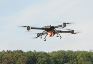
Kathleen Swain, a underwriter at USAA who is also a licensed pilot and flight instructor, told Fast Company that the insurance agency wants to fly PrecisionHawk unmanned aerial vehicles (UAVs) over disaster areas in order to research claims. By flying a drone over disaster areas, the insurance company could potentially research claims much more quickly and cheaply than they could on foot, via car/truck, or via helicopter--which could speed things up in areas where roads are inaccessible. PrecisionHawk is also developing drones designed for use on farms and for surveying and mapping as well.

Read more…

DroneDeploy Co-Pilot

3689620737?profile=original

I recently had the opportunity to set up a vehicle with the DroneDeploy Co-Pilot.  https://www.dronedeploy.com/

The integration was two very simple connections to the Pixhawk.  1) A 6pin to 6pin DF13 cable from the Co-Pilot to Telem2 on the Pixhawk.  2) A 5v lead from the Co-Pilot to a 5v BEC on the vehicle.

The benefit of this integration is two fold.  1) Fully autonomous control of different cameras over Wifi.  2) LTE cellular connectivity to transfer data from the payload to the cloud with low latency while in flight.  This enables mission planning, execution, real-time monitoring and post-flight analytics over a 4G cellular link to a web browser anywhere on the Internet.

There must be a safely pilot present to power up and push the arming button.  All other functions can be controlled from a remote browser.  The local safety pilot can override modes with the RC transmitter.  (tested!)
Here's the main dashboard where you start your missions.  Because of the high-bandwidth link, everything is updated in real-time.  For each completed mission, you can see how many pictures were taken and uploaded to the cloud, date, camera type...this data upload happens automatically while in flight.  Then you click on the blue maps button about 25 minutes after the flight to go to the map page.
3689620794?profile=original
The map page displays all 4 data outputs, including an embedded SketchFab view.  This is from a GoPro.  The camera control is done from the companion computer via WiFi to the GoPro Wifi App.  You only need to turn on the WiFi on the GoPro.  The WiFi did not produce any range issues with the redundant RC link.  Our next step is to begin resolution and quality comparisons with other cameras and other software tools.
3689620695?profile=original
3689620805?profile=original
3689620746?profile=original
There is also a very nice post flight analytics tool.
3689620858?profile=original

I must say that I'm impressed with the work from the team at DroneDeploy, and I look forward to their progress!

JC

Read more…

3689620672?profile=original

Some of you might have read the work that Siddharth, Andrew, Philip and myself (supported by many others) have been doing over the last months with APM in Linux through the BeaglePilot project. We are happy to share with you today a paper titled "Towards an Open Source Linux autopilot for drones" (available  here) that has been accepted in LibreCon 2014: Business and Open Technologies Conference that will be held the 11th and 12th of November in Bilbao, Spain.

The paper will be presented by my colleagues from Erle Robotics and they will also be showing our drones flying with APM in Linux. Feel free to drop by and join.

Code availability:

Most of our work with the AP_HAL_Linux has already been merged in the master branch of the main APM repository. We would be happy to address any comments either here or through issues in the main BeaglePilot repository. 

Acknowledgements:

As we point out in the publication, this work would not have been possible without the support of many people. We sincerely want to thank DIYDrones community members for their support, words of encouraging and guidance. We also like convey thanks to Beagleboard.org, Google, 3DRobotics and Erle Robotics for providing financial means and material.

We would like to highlight the importance of having Andrew Tridgell (tridge) as our mentor through all these months. We can only thank him for his support and patience. It has been an amazing experience to work under his supervision and nowadays, more than ever, we deeply respect the work he and many other developers have done to bring up APM to this level. We wish that this contribution is just the first of many that will (hopefully) benefit the community.

Read more…

Mavlink data displayed on Taranis, without converter

3689620635?profile=original

Having already got my OpenLRS set up to send Mavlink data back from my plane (using the gitsly OpenLRS branch), the next step was to get Mavlink data displayed on my Taranis.

The Taranis need inverted levels to serial pin in the module bay so I build an inverter from the schematic here. 

I saw this topic a while back: MAVLink data displayed on OpenTX (9X/9XR/etc) radio screen via OpenLRS, plus telemetry pass-thru to PC and assumed this would also work on Taranis. No such luck! There is no EXT=MAVLINK option for Taranis in the configurator. 

However I managed to get the OpenTX build environment set up on Ubuntu following the instructions here without too many difficulties. Then is was a matter of redirecting the telemetry bytes into the existing mavlink code, and displaying the Mavlink settings and telemetry screens rather than the Frsky ones. I was quite surprised when it all worked however!  The Mavlink serial is also available from the serial connector on the OpenLRS module so that can be connected to a PC or Android device.

In the original 9X Mavlink firmware it was not possible to select which telemetry protocol to use except by reflashing. I need a mixture of S.Port and Mavlink telemetry depending on which plane I'm flying so that didn't suit me too well. I added an option in the model menu telemetry options to use Mavlink rather than S.Port or Dbus, so each model can have it's Mavlink or Frsky telemetry received and displayed :) . 

I also thought it would be useful to have the radio read the flight modes as they are receiver over Mavlink, this wasn't too hard to incorporate either. I created sound files for each Arduplane mode and added code to play them on receipt of a new mode.

Something else I would like do is to copy the Mavlink data into the normal Frsky variables so that they can be used in the normal way, i.e. read out, used in Lua scripts and for vario sounds etc.. It's on the to-do list.

Hopefully this will be useful to some people out there, I will post the code after I get a chance to clean it up slightly as it is a bit of a hack! For now the binary and sound files are here (they need to be in the SOUNDS/en folder):

https://drive.google.com/folderview?id=0B4xnWmfKh4FrVFl4YlU1Zm9nQU0&usp=sharing

Cheers,
Sam

3689620752?profile=original3689620710?profile=original

Read more…

the latest prototype, UAV 270

3689620361?profile=original

3689620335?profile=original

My recent bout if insomnia resulted in the above. Should be a lot of fun for FPV. The roll bars and added boom support as I am going to try a larger from rotor distance and maybe a differnt size motor all together. Front to back, recently spoke to a friend and asked why not use a pillow block on the front, add a servo and tilt rotor here we come.

The wires were deliberate at the end but then evolved into the fire breathing dragon. The VR Brain micro is the FC. So far I am impressed with the compactness of the design, I spent a ton of time on wire management.

There is a Twin Adjustable voltage regulator PDB, on set to the 5V and the other to 12V. The LEDs are integrated from the FC for notifications, and will get some video of that in action hopfeuly.

Read more…
Moderator

With VR Micro Brain 5 is possible to develop very light , only 9 gr , fully autonomous drones , in last months i developed different kind of prototype the main targets was :

- Very light platform only 439 gr.

- With support of micro brushless gimbal 150 gr. 

- Support of automatic fly support with high reliability after a lot of test i   developed new kind of technology :

  • a new GPS : VR GPS 8 based on new generation of Ublox 8.
  • a new VR Leash a device for full control of drone in very simple way.
  • a new VR micro gimbal 2-3 axis based on nuttx OS with native mavlink support.

- My last target is a long time flight , the first revision of micro drone flew for only 8-10 minutes , now with last updates , new custom motor propeller and battery our time of flight is 27 minutes :)

This is the video of early version of new frame for long time of flight , need to solve some vibration problem i doing all test using EKF and APM Copter 3.2rc12 all work very well.

The next week will be present the new very nice and light frame for our Micro Brain from VR Mechatronic Lab :)

Read more…
Moderator

No hiding behind AC 91-57 anymore

3689620087?profile=original

The FAA just cancelled AC 91-57 the one that many folks used to justify commercial aerial photography from unmanned aircraft in the USA. 

Now look to the “full special” interpretation for Model Aircraft for your guidance.

Patrick said this at the time about that.

Folks in the U.S. UAS community (which now including paper airplane aficionados too) were surprised and dismayed by the FAA’s “full special” interpretation for Model Aircraft. The community is completely flabbergasted by the lack of response from the regular gaggle of advocacy groups. UAS freedom(s) just took a major hit in the U.S. and folks are asking where the hell is the leadership? We are usually treated to quick responses (canned goods) heralding any announcement from the FAA (no matter how trivial or nonsensical they may be), as enlightened and a giant step in the right direction. We can guess who got the special dispensation/backroom deal neutering.

Shocked and awed –

The community is collectively wondering what’s up with the subdued response? Where is the mobilization of the membership(s)? Adding to the dismay is the notion that this edict could have possibly caught advocacy groups off guard? It has many feeling like we just suffered a regulatory tsunami without warning and no disaster plan!

* To everyone’s integration credit… The FAA did state repeatedly that the hobby would look the same after regulation was announced. However, in this instance it would appear that reality and the FAA have parted company again.

If you want to join the Hollywood set these are the requirements for your platforms 

We commissioned our art department at sUAS News to create this simple graphic to explain the system over there ;-)

Slide1.jpg

Read more…

SteadiDrone IRIS/IRIS+ Conversion Kit

.

untitled-1_1_3.jpgI ran across this conversion kit on the SteadiDrone web site.

Transfer your existing electronics, flight controller etc over to an airframe with SteadiDrone's 'rapid deploy' folding design and high quality carbon and aluminum construction, add four powerful top end motors and transform your IRIS into a professional aerial rig! With loads of room for extras like FPV, camera gimbals and more, fly SteadiDrone's high performance airframe and you will never go back. 

IRIS Conversion Kit Includes:

  • SteadiDrone DASH Airframe Kit
  • SteadiDrone Carry Box with custom high quality foam
  • 4 x SteadiDrone MT3506 Brushless Motors
Read more…

3689620192?profile=original

Some of you may have noticed that your multi-copter will lose from 1.5 to 3 or 4 meters at the end of a horizontal run when in any of the Altitude Stabilized modes, like Alt Hold, Loiter (and PosHold for 3.2 candidates) or Auto.

Several heated debates have considered the reasons and possible causes, until finally a more demonstrative test was undertaken, using the 3DR X8 above with Pixhawk

But first some ground data:

The following graph shows how the altitude influence is directly affected by velocity (especially forward velocity), but to a lesser extent latteral velocity.

3689620069?profile=original

A general conclusion is that a "pressure bubble" forms in front of a moving object:

3689620210?profile=original

This is an image of a pressure gradient around a sphere moving towards the left of the image. This gradient is greater or less depending on the physical configuration of the vehicle. The vehicles that are most effected by the altitude drop tend to be less streamlined, with greater frontal area, and therefore a greater pressure buildup.

As the vehicle accelerates, the pressure starts to rise slowly and the forward tilt of the vehicle moves the higher pressure area more directly into contact with the altitude sensor. Then with sudden slowing, quick pitch changes and dropping pressure simulates that the vehicle is rising. Altitude controllers react to counter the effect and the vehicle drops..... sometimes like a rock.

So whereas the debate postulated that software should be able to resolve this problem the problem remains that, if it's really true that the cause of the problem is the "pressure bubble", then the software can only react to what it "sees and feels". If you make the assumption that it is possible to generate a countering force at the end of forward travel, you may end up sending the vehicle into space if the wind is from behind. The processor doesn't know any more than it can "feel".

So I built the testbed above to test the theory. You'll see a tube coming out of the front of a Pixhawk, just about where the altitude sensor is. There's a hole in the Pixhawk cover, and the altitude sensor is sealed with Plastecine, so that the outside air pressure from the "static sensor" is fed directly into the altitude sensor.

The white plastic rectangle on the other end of the tube has a tiny hole (not very visible in this photo, but about 1.5mm diameter) drilled from side to side, and then another hole of the same diameter leads from those holes to the tube. In this way, forward movement does not exert any pressure into the tube, furthermore, as the vehicle pitches forward, the static sensor holes move down into a lower pressure area outside the bubble. Pitching back up, if anything the static holes move into a slightly higher pressure area. the end result is ZERO DROP in altitude.

Lateral movement has no effect, as the side to side holes let flow pass though unrestricted and no pressure gain is seen.

This baby flies as flat as a pancake!

Read more…

3689620046?profile=original

Applanix, a mobile mapping and positioning company, has introduced a new product that enables major improvements in unmanned airborne mapping: the Applanix APX-15 UAV GNSS-Inertial System. The announcement was made at InterGeo, being held this week in Berlin

.

The APX-15 UAV is designed to maximize the efficiency of mapping from small unmanned aerial vehicles (UAVs) by reducing — or even eliminating — Ground Control Points (GCPs). Sidelap is also significantly reduced, increasing the area flown per mission. The Applanix APX-15 UAV provides performance in a small package and, with the included POSPac UAV post-mission software, produces a highly accurate position and orientation solution for direct georeferencing of cameras, LIDARs and other UAS sensors, the company said.

“Applanix has recognized the need to provide the growing UAS mapping market with the same highly efficient solutions that it pioneered for airborne mapping over 15 years ago,” said Joe Hutton, Director of Inertial Technology and Airborne Products at Applanix Corporation. “We are offering a cost-effective solution that meets the size, weight, power and cost requirements of small UAS, and maintains the Applanix pedigree for quality and performance.”

The APX-15 UAV, measuring just 6 cm x 6.7 cm and weighing only 60 grams, features a high-performance, survey-grade, multi-frequency GNSS receiver and low-noise MEMS inertial sensors all on a single board. The Applanix IN-Fusion GNSS-Inertial integration technology runs directly on the GNSS receiver, resulting in an ultra-compact design, while superior performance is achieved from the inertial sensors using the Applanix SmartCal software compensation technology.


APX-15 UAV is expected to be available worldwide in the first quarter of 2015 through the Applanix sales channel.
With 220 channels, the APX-15 UAV tracks all available GNSS satellite signals including GPS L1/L2/L2C/L5 and GLONASS L1/L2, QZSS, BeiDou and Galileo, and provides a highly accurate post-mission and real-time RTK GNSS-inertial position and orientation solution to support guidance and control, precision landing and sensor geo-referencing.

Read more…

Heavy lifting VTOL technology, frames.

3689620111?profile=original

I just tried to edit my post and I hope that all the comments didn't get deleted.

If so, I will have to go back through what I had, and try to add them in. oops sorry won't do that again.

There are fundamental principles such as:

Maximizing airflow, Minimizing weight, Frame Rigidity, Vibrations(mode, frequency, amplitude, localization), Torque.

In the arms specifically: There are torsional from the blades spinning, and lever forces, from the lift generated.

Compression is generally to be avoided, it can fail in a big way, so be careful with it. Oversize is better.

There are probably others so feel free to add. Those are common to all frames.

Most copters use a round boom or arm. This is bad in a wind tunnel. And if they get damaged, you have to replace the whole thing. My suggestion is to use vertical arms, allowing the downward force of the propeller to have the least resistance. Having vertical arms and using thin extruded aluminum not only make it easier to fabricate, it also makes it eco-friendly because you are not wasting fiberglass or carbon parts. You can bend the aluminum back into the proper shape effortlessly.

The torsion forces can be converted into bending/lever forces by appropriate locations of mounting points. This will increase stability because torsion is a pain to deal with. Tension is the best for most thin metals so trying to keep that in mind, putting some parts in tension will reduce needed material. Using a steel or similar wire around the arms will provide tension force against any torsion or bending because any individual arm's movement will be transferred to the other 3, causing them to act as a rigid body, it avoids sending vibrations down the arm.

By having the arms come to a central point, there is symmetry in the forces involved, makes them easier to design around.

If this is helpful at all, a thank you will do, and if you have anything to add, I will keep a record here AND in my heavy lifting design files, which will be used to make the next version of the ADrone. And I won't leave you out where credit is due. Collaboration is the future and we can do it together!

here is the work I am talking about, this is the first version, I know I am late to the drone field but that's no reason to quit.

http://www.instructables.com/id/Aluminum-sport-X-copter-frame-design-for-strength-/

Read more…

Plexidrone - Latest Crowdfunded Drone

3689619892?profile=originalThe Plexidrone launched on Indiegogo at the beginning of October and successfully cruised past it's initial funding goal of $100k within the first week of it's campaign. Like all successfully crowdfunded drone campaigners, the DreamQii team have been quite creative marketing the virtues of their creation and proactive in generating press for their campaign.

The primary USP they are using to differentiate the Plexidrone from the competion is the 'swarm' feature. To quote the campaign video "You will definitely find no drones that you can control using a swarm technology. It's completely new, something you wont find anywhere else". ArduPilot does however offer something like that. It's other unique selling points include an integrated speaker aimed at replacing/augmenting the role of the status LEDs, as well as retracting legs, a clip based payload attachment system and navigation lights.  The Plexidrone also features removable arms with some form of quick connection attachment for compact stowage and easy setup, and (perhaps the best USP of all) it also comes with a rather neat looking custom carry pack.

In terms of smarts, it appears that the flight controller they are using has much in common with ArduPilot, however, if it is (which it obviously is), they don't appear keen to make it known when quizzed on the matter.  The Bluetooth telemetry bridge also appears to be very similar to the one developed by Jeff Taylor and launched on Kickstarter last year.  It will be interesting to see how much their app, which will be available free on both iOS and Android, has in common with Arthur Benemann's DroidPlanner, or whether they get their iOS app out before Helico Aerospace Industries do.

The front facing ultrasonic sensor is an interesting addition. Based on the video and the delicate wording used to promote it, it appears that the proximity feature may simply offer an audible warning to the pilot or people in close proximity with the aircraft (of an immanent collision in the forward direction), however the website states that Plexidrone has Obstacle Avoidance effective up to 6.5m (3m on the tech specs), so it seems a little unclear what it will be able to do.

Interestingly, while initial press and some of the product images on the campaign page show what appear to be quality SunnySky motors, proper threaded mounts and snazzy props, the production unit appears to be wearing Turnigy 2830/11 1000kv motors, old-school collet style adapters and cheaper props.

In terms of performance, it is a little on the heavy side for it's size, weighing in at a sturdy 1.3kg with a modest 3S 5Ah battery, yet flight time is claimed to be up to 35-minutes (which seems about twice what one would expect from the selected configuration, even without a payload attached).

Anyway, it will be interesting to see how this project tracks and whether it gets big like Pocket Drone, Hexo+ and AirDog.  Other discussions on the Plexidrone (including comments by one of it's creators) can be found here and here.

Read more…

CanberraUAV UAV Outback Challenge Review

3689619848?profile=originalNow that we’ve returned to Canberra and taken a well-earned break, we have spent some time reviewing our performance at the OBC. The following article is a review of what we did and didn’t do well as a group at the OBC.

Winning the OBC, whilst an awesome achievement, has also provided us the chance to act out a search and rescue scenario as a team. Thus a review of our performance at the OBC provides some valuable information on how we can improve ourselves in future “real life” S&R scenarios, in addition to providing hints and tips for other likeminded UAV organisations.

Note that this review is from a generally non-technical perspective. Fellow team member Andrew Tridgell has written an excellent technical review of our performance at the OBC.

Things we did well:

The two radio systems (5.8 GHz Ubiquiti Rockets and 928MHz RFD900’s) used for telemetry and imagery worked quite well. The automatic failover between the two links worked flawlessly and enabled us to easily work outside of the range of the 5.8GHz datalinks for parts of the mission.

The Pixhawk/APM:Plane flight controller tracked the waypoints during the mission extremely well during periods of strong gusting winds.

Our image recognition hardware/software found the missing bushwalker easily and quickly displayed it on our screens. Repeated passes over Joe allowed us to get a high accuracy on our estimated position of him.

The wind correction algorithm for our bottle drop, whilst simple, worked extremely well. During testing, we’d used our data to develop an empirical formula for predicting the bottle drop location based on the aircraft’s position and speed and the direction/velocity of the wind.

Things we didn’t do so well:

Labelling of power ports – during setup, we accidentally killed the ethernet switch used in the Ground Control Station (GCS) network (as we had multiple GCS operators/laptops) by plugging the switch into a 12V plug instead of the 7.5V plug. Fortunately, we’d bought a spare switch with us!

Checklists and communications were definitely an item we’d not tested and developed enough. There was confusion about who was doing which check and when on the checklists. Some critical items were left out of the checklists.

Our takeoff and landing (done automatically by the APM) were marginal, far below our usual quality. The takeoff in particular raised some  concerns from the OBC Judges, as the UAV was blown off course towards the GCS and Judge’s tents during takeoff. From an organisational perspective, several things did NOT happen:

  • We did not take the wind into account during our takeoff preparations
  • Lack of practice in taking off in windy conditions
  • Lack of communication between the GCS and Pilot as to the wind conditions
  • Lack of practice in aborting automated takeoffs

At the end of the day, we were very focussed on gaining the extra points in the OBC (for an automated takeoff and landing) and we never stopped to properly consider the circumstances under which the automated takeoff would not be appropriate.

During the mission itself, our antenna tracker required slight offsets to track the UAV properly. Part of this was due to a different magnetic environment at Kingaroy (compared to our home base in Canberra) degrading the compass accuracy. In addition, we’d never considered having to set up the antenna on non-flat ground!

As mentioned previously, the landing to Kingaroy airport also presented some issues. One again, the wind had its own ideas and carried the aircraft past our nominal landing point and it did not land until much further down the runway, finishing up very close to the geofence. As with the takeoff, we did not consider the effect of strong winds on our aircraft during this phase, nor did we have experience in landing in strong winds.

So, for other UAV operators out there, we offer the following advice:

  • Don’t just have checklists – use them regularly and continuously improve them
  • Practice flights in a variety of wind conditions. Know the limits of the airframe and of the automatic flight modes in these wind conditions
  • Ensure that safety is always put first - have a safety management system. UAV’s do have the potential to hurt or severely injure people!
  • If operating in a team, make sure that everyone clearly knows what their responsibilities are. Checklists and operations manuals work well for this. Following this, regular practice with a full UAV/GCS setup with the entire team is a must

A full review list is available at https://canberrauav.readthedocs.org/en/latest/lessons/OBC2014/review.html

We'd like to thank 3DRobotics for their very generous support of CanberraUAV for the 2014 UAV Outback Challenge. Thanks also go to all the individuals we've collaborated with, to further the field of S&R UAV platforms.

Read more…

BzapGAPCUAI_lgX.jpg

Roma Drone Conference, which starts today, is the first of a series of UAV related conferences that will be held in Rome to discuss about many UAV aspects like safety, privacy, rulemaking, tecnology development related to "Drone Journalism". One of the most important display will be demonstration flights, because two companies (ItalDron and FlyTop) got the first Autothority approval for flight in "Critical Scenarios" (i.e. urban areas), a milestone for italian UAV scene!

Coverage here (italian language):

http://www.vanillamagazine.it/italdron-vola-su-roma-in-uno-scenario-critico/

http://www.dronezine.it/8416/domani-prima-missione-autorizzata-enac-su-roma-per-la-conferenza-drone-journalism/

Read more…
Moderator

RIEGL RiCOPTER with added LiDAR

RIEGL_RiCOPTER_UnmannedAerialSystem_equipped_withVUX-1LidarSensor.jpeg

First one I think to come with LiDAR as standard, that's an interesting development for sure. I see the sun setting on photogrametry with RPAS. But we were talking about that five years ago ;-) Interesting that it is what it is, enough to get the job without too many hours of extra to make it look fancy. I should think most people here could build similar.

RIEGL is excited to announce the release of the RiCOPTER! RIEGL is the first major LiDAR manufacturer to develop its own unmanned aerial system. The RiCOPTER is a high-performance UAV equipped with the RIEGL VUX-1 survey-grade LiDAR sensor to offer a fully integrated turnkey solution.

Stop by the RIEGL booth to see the VUX-1 integrated into several other UAS systems, such as SARAH by Flying-Cam or Aeroscouts UAS, demonstrating the versatility of the instrument! Moreover live demonstrations of RiCOPTER will be performed Tuesday – Thursday in Intergeo’s UAV flight zone.

Rest of the press release

Read more…