I just designed and printed this. It snaps together in a few seconds and provides a good way for me to keep my radio pointed vertically. Seems very stable even with the longer antenna. You can find it on thingiverse if you want to print one for yourself Check it out here.
All Posts (11086)
Sort by
At Event 38, part of our goal of offering low-cost, ready to fly UAS is to promote their adoption into a variety of alternate uses. We recently partnered with the physics and engineering departments of Universidad de Chile to explore the viability using an E382 to study low altitude atmospheric effects.
As a preliminary study, we set out to measure the size of the boundary layer over Santiago, Chile as it grows over the morning hours. In the graphs below, you can see the edge of the boundary layer as the area where the temperature starts to increase at about 910-925 hPa.
It’s only visible in the first two graphs because after that time it had grown beyond the altitude we were testing.
The flights were spaced 20-25 minutes apart and lasted about 15 minutes each. For these missions we used guided mode and simply reset the altitude after a few minutes at each altitude break.
The advantage of using UAS in this scenario is the ability to reach both low and high altitudes quickly and repeatably. Logistically it is much more portable and cheaper per flight than weather balloons or tethered balloons.
Hopefully this is part of the future of small UAS once they’re completely integrated into the airspace worldwide!
Finally the last missing board from the PX4 series has been released, the PX4FLOW smart camera module. It can replace GPS in indoor and outdoor applications and provides a metric position close to the ground with only very little drift. It is essentially a microcontroller hooked up to an automotive-grade machine vision sensor that can be freely programmed.
Given the wide distribution of the AR.Drone one might ask what the purpose is, and the answer is simple and well illustrated by the video: You can use this board with PX4FMU and the PX4 native autopilot stack, but you can also interface it with any other system, including Linux onboard computers running ROS. It works indoors and outdoors and brings the same stability the AR.Drone shows in flight to any aerial robot.
It has a native resolution of 752×480 pixels and calculates optical flow on a 4x binned and cropped area at 250 Hz (bright, outdoors), giving it a very high light sensitivy. Unlike many mouse sensors, it also works indoors and in low outdoor light conditions without the need for an illumination LED at 120 Hz (dark, indoors).
- 168 MHz Cortex M4F CPU (128 + 64 KB RAM)
- 752×480 MT9V034 image sensor
- L3GD20 3D Gyro
- 16 mm M12 lens (with IR block filter)
As the aerial image with overlaid trajectory shows, the position estimate is very accurate. This is without GPS, captured in flight at 1.6 m altitude and in one pass.

The work on this module has been accepted at the International Conference on Robotics and Automation (ICRA 2013) in Karlsruhe, Germany: Dominik Honegger, Lorenz Meier, Petri Tanskanen and Marc Pollefeys. An Open Source and Open Hardware Embedded Metric Optical Flow CMOS Camera for Indoor and Outdoor Applications, ICRA2013
The module has been developed by Samuel Zihlmann, Laurens Mackay, Dominik Honegger, Petri Transkanen and Lorenz Meier.
Frequently Asked Questions
- When will it be available? - It is available here and starts shipping next Monday, according to 3D Robotics
- Is the software available? - The software will be made available shortly open-source licensed. The module comes pre-flashed with the latest state.
- Is a ROS interface available? - Yes, here
- Will you offer a low-cost version? - The module has been designed to meet scientific standards and provide a baseline for what one can achieve with a reduced design. A low cost version is not planned, but we're interested to hear if someone is willing to contribute a cell-phone camera based design.
- Can I hook it up to robot XY? - Almost for sure, as it outputs the flow already in m/s and in MAVLink format
- Has it been used in scientific work yet? Yes, for example in this paper by Fraundorfer et al.
More information needed?
Here are some photos and a short video of a 80mm diameter fully articulated turret Ball, currently fitted with the FLIR TAU-2 IR video camera.
Camera and lens is approx 100grams. Complete assembly is 220grams. Camera line of sight view is from 15deg below horizontal, full 360deg coverage. The Ball can be fitted with the smaller Sony Block cameras as well. Ball is 78mm OD - see the dimensions added to the one image right at the end.
The complete structure is made from composite. Male and female molds were machined from Polypropylene for the two half-domes. Timing gears and belts all from RS Components in South Africa.
From start of 3d CAD model to this prototype was 2 weeks.
The Gimbal is currently fitted to our SurVoyeur Aircraft, ready for Night Flight trials with the Ministry of Nature Conservation here in Namibia.
Here is a YouTube video of it working:
all Underside Assembly Side View
FLIR TAU-2 camera
First off who I am:
My name Eugene Lawson
I have always had an affinity for things that fly. As a young child my uncle wanted to fly military (he went Navy AOCS). And showed me Iron Eagle (yeah that movie) I was hooked. But my grades were poor in high school and I didn't know that I had to earn a commision to fly. So I went to the #2 thing that I loved Computers
I am a Software engineer with Crestron Electronics. (7 mos). I have been programming for about 18 years.
Within that time frame I have worked out at White Sands Missile Range (WSMR) as a defense contractor working with DFCS (Drone Formation Control Systems). Basically, code moves drone (aerial or ground based) targets, and the military test its weapon systems on them. Apparently you can't fire weapons at them if people are in and controlling them (go figure). seems like a perfect job for death row inmates but hey.. that's just me.
Since then I made 3 commercial video games for the ps3 and xbox360 and pc. This got me very interested in Artificial Intelligence and Finite State Machines.
Being at Crestron there is a lot of hardware here. So I joined up with former co-worker or current co-worker actually (it's complicated). And we started a small Quadcopter project.
Our current skill set:
Programming 40 years combined programming experinece
5 years Drone experience. (mine)
6 years Game programming experience.(mine)
10+ years electronic experience (his)
We know NOTHING about quadcopters, flight physics, ect. We are banking on our ability to read, current experience and knowledge to get this working.
There is definitely something to be said about learning from previous mistakes and accomplishments of others, but on this project, I feel that more can be learned by independently building this machine. We also feel that maybe by working independently we might find new ways of handling things. Probably for the worse, but could be for the better. That being said, if you view our videos, post, ect. Look at them as a... "look at what these idiots are doing now!" and not as a "How to" posts. Because more likely than not, we will be doing it completely bass ackwards.
As of right now I have already shorted one 3S Lipo 25C 5Ah. I cut the leads off the battery AT THE SAME TIME! (yeah I know right?!) I couldn't have just read in the forum.
I do suspect we'll gather a lot of data. So feel free to look at that and gather what you will from it. Oppose to what we say we are getting from the data.
We are very excited about this project. Our first test is scheduled for this weekend (weather permitting). Provided we don't throw a prop into our chests, I will post our vids, findings, and data.
Talk to you all soon (I hope?)
The Congressional Research Service has done a new report on US drone policy. You can read an overview of it here from the Federation of American Scientists, which originally obtained the report.
Here's the abstract:
Under the FAA Modernization and Reform Act of 2012, P.L. 112-95, Congress has tasked the Federal Aviation Administration (FAA) with integrating unmanned aircraft systems (UASs), sometimes referred to as unmanned aerial vehicles (UAVs) or drones, into the national airspace system by September 2015. Although the text of this act places safety as a predominant concern, it fails to establish how the FAA should resolve significant, and up to this point, largely unanswered legal questions.
For instance, several legal interests are implicated by drone flight over or near private property. Might such a flight constitute a trespass? A nuisance? If conducted by the government, a constitutional taking? In the past, the Latin maxim cujus est solum ejus est usque ad coelum (for whoever owns the soil owns to the heavens) was sufficient to resolve many of these types of questions, but the proliferation of air flight in the 20th century has made this proposition untenable. Instead, modern jurisprudence concerning air travel is significantly more nuanced, and often more confusing. Some courts have relied on the federal definition of “navigable airspace” to determine which flights could constitute a trespass. Others employ a nuisance theory to ask whether an overhead flight causes a substantial impairment of the use and enjoyment of one’s property. Additionally, courts have struggled to determine when an overhead flight constitutes a government taking under the Fifth and Fourteenth Amendments.
With the ability to house surveillance sensors such as high-powered cameras and thermal-imaging devices, some argue that drone surveillance poses a significant threat to the privacy of American citizens. Because the Fourth Amendment’s prohibition against unreasonable searches and seizures applies only to acts by government officials, surveillance by private actors such as the paparazzi, a commercial enterprise, or one’s neighbor is instead regulated, if at all, by state and federal statutes and judicial decisions. Yet, however strong this interest in privacy may be, there are instances where the public’s First Amendment rights to gather and receive news might outweigh an individual’s interest in being let alone.
Additionally, there are a host of related legal issues that may arise with this introduction of drones in U.S. skies. These include whether a property owner may protect his property from a trespassing drone; how stalking, harassment, and other criminal laws should be applied to acts committed with the use of drones; and to what extent federal aviation law could preempt future state law.
Because drone use will occur largely in federal airspace, Congress has the authority or can permit various federal agencies to set federal policy on drone use in American skies. This may include the appropriate level of individual privacy protection, the balancing of property interests with the economic needs of private entities, and the appropriate safety standards required.
From Hackaday:
This gentleman is using electrical impulses from his neck muscles to fly a toy helicopteraround the room. The project is a demonstration of the AsTeRICS project which seeks to reduce the complexity of adapting the set of skills a disabled person can use to do a wide range of functions. In this case, controlling the helicopter could easily be switched to other tasks without changing the user interface hardware.
One of the plugins for the AsTeRICS project uses the OpenEEG library. This reads the signals coming from a pair of electrodes on top of each shoulder. In the video after the break you can see that as he flexes these muscles the changes in signal are mapped to the altitude of the helicopter. This is just one example of a wide range of inputs that include things like building a webcam-based mouse or using facial recognition.
The toy itself is being driven by an Arduino sending IR commands. We’ve seen quite a few project where the helicopter communications protocols are laid bare.
ABC News/Univavision has a great profile of Jordi today. The video segment is here (embedding isn't working here) and the text is below. It's quite long, but here how it starts:
At 20 years old, Jordi Muñoz found himself in Riverside, Calif., an hour east of Los Angeles with not much to do. He'd settled there to wait for a green card after leaving Mexico to start a family with his wife, a U.S. citizen. He was away from friends and family, and he could not work or continue school in the U.S. either. So, with an internet connection and his programing skills, he began tinkering with a remote control helicopter.
"I was extremely bored," he said. "I could only watch TV or program something, so I decided to program."
In his bedroom he tweaked his toy, splicing motion sensors of a Nintendo Wii controller with the mini copter. He calls those eight months "the most productive months of my life." That's because his pet project put him at the front of a budding industry: the personal drone market.
His eureka moment came when he was able to stabilize the helicopter's flight using computer code. He posted his progress on DIY Drones, an online community started by Chris Anderson, who was editor of Wired magazine at the time. Muñoz also acquired more and better sensors, like a geographical positioning system, or GPS, probably the most important component on a drone, he says.
Anderson took an interest in Munoz's work. He found Muñoz's accomplishments "impressive" and began collaborating with him virtually.
"He was able to quickly learn about very advanced technology. He did all that by teaching himself on the internet," Anderson said. "He's that generation of people who don't know what they don't know. He didn't know he was supposed to have a PhD to invent a drone. He just did it."
Read the rest of the article here.
Many R/C and Robotics enthusiasts build Robotic Vehicle parts using 3D printing and find the technology very useful. A group of scientists from the European Space Agency took it to the next level!
Hey everyone,
First off I am happy to announce The First round of Techpods will start shipping Feb 21st!
here are some shots of my latest build. Has 10,000 mah of 6s lipo, an APM 2.5,and minim OSD. Going for a 3.4 hour flight. They are still available for pre-order at hobbyuav.com.

I wonder if it is a practical idea to integrate air traffic data with all the other data we track in the GCS and the OSD. Data seems to be available. I don't see a complete solution in hand but some pieces are there., It looks like there is a growing standard for position reporting (ADS-B) and you can buy a receiver that will allow you to track air traffic in the area. This will only track aircraft that are equipped with ADS-B, but that is in growing numbers and is more prevalent in Europe. There is other data available too, from the FAA, that covers aircraft based on Radar and transponders (I think) for that data there is a 5 min delay that limits its usefulness.
Pictured above is a nifty item, reminds me of the 3DR radios!
This is an example of a receiver that can be connected to a laptop and display a map of local traffic. I'm sure it could easily be hacked and the data turned into waypoints.
There are several networks and software available to allow you to contribute data as well as receive data even if you do not have a receiver. This can work similar to how the findu.com network works for hams using APRS. To me, this seems to be a next logical step for hobbyists who are using altitudes higher than a few hundred feet.
I wonder if the drone community as a hold has an interest and see it as being practical as something that could increase safety, or is this a "dude" idea?
If you would like to learn more, here are a few links i found:
First look at these monsters coming soon!
My dream of an airbot-hammock might just come true after all...
Here is the request for input on developing a new line of motors "tailored for UAV applications"
Am I doing the math wrong? Or is this just cute little copter just crazy expensive?
The nano helicopter has been developed by Prox Dynamics AS of Norway as part of a £20m contract for 160 units with Marlborough Communications Ltd (MCL), Surrey.
I love Lego Mindstorms (it's how I got my start with drones), but it's pretty heavy. You need a lot of helium to lift all that plastic. Via Makezine:
This blimp uses two 55″ helium balloons, Dexter Industries NXTBee wireless modules, a servo, and two DC motors. One of the creators, Tyler Westmoreland, shared the RobotC code.
We're hoping to relaunch our own blimp project later this year. I loved our old Blimpduino, but the sensor technology didn't exist back then to really let it autonomously navigate indoors. Now it does ;-)
First of all, sorry for the unexciting video. Waiting on my new gopro so I made do with an old keychain cam.
Flight went well! I was very impressed with the RTL performance straight out of the box. The Radian displayed much less of a tendency to wander than the 6' Telemaster I had flown with APM before. I will take a stab at tweaking the gains. This first image is just the RTL flight and the next one is all the flight data.
Before landing, the plane didn't want to come out of RTL mode, so a lot of frantic switch-toggling happened and eventually it came back. Not sure what the issue was.On the plane, I have the auxiliary antenna set up orthogonal to the main RX on board so antenna nulls shouldn't have been an issue....
Like I said, onboard video isn't great. RTL starts at about 2:17.
All in all, not a bad morning!

I have been asked a few times now how I got my GCS basics up and running. MAVLink is a rather complicated protocol to implement. The documentation is rather thin and partially outdated... Not an easy thing, if you are no experienced developer...
I'm no pro developer by a long shot. I speak reasonably well C and I did some smaller projects in JAVA. All in all, I can hold my own but can't do nor understand really fancy stuff. Without the help of Pat Hickey, who answered many of my questions on the mailing list, I wouldn't have gotten very far, so first of all, thanks again to him and the others!
Now, how do we get a MAVLink interpreter going?
The first thing to do would be to snatch a copy of the GCS_MAVLink library from the Arducopter project. You will also need AP_Common, AP_Math and FastSerial for dependencies. FastSerial must be the first to be included in your sketch.
Then, go an grab the code of ArduStationII. When you have that, open 2 windows: One with the code of MAVLink.pde from ArduStation2, the other in the GCS_MAVLink library subdir include/mavlink/v1.0/common/
Then, in MAVLink.pde, look at void gcs_handleMessage(mavlink_message_t* msg). This function is called by gcs_update and does the main decoding work. Basically, it's a huge switch-case block which switches on the message id of the received package. Let's have a look at one case block:
  case MAVLINK_MSG_ID_ATTITUDE:
    {
      // decode
      mavlink_attitude_t packet;
      mavlink_msg_attitude_decode(msg, &packet);
      pitch = toDeg(packet.pitch);
      yaw = toDeg(packet.yaw);
      roll = toDeg(packet.roll);
      break;
    }
That doesn't look so complicated, does it? ArduStationII works mainly with global variables for all the interesting parameters. So what they do is, for everything they want, they knit a case block, fishing for the right message id, then call the respective decode method and assign the values to their global variables.
Let's have a look at something that isn't included in ArduStationII. In the common directory, search for mavlink_msg_vfr_hud.h and open it in an editor.
The very first thing in this file is the definition of what's in a MAVLINK_MSG_VFR_HUD packet:
typedef struct __mavlink_vfr_hud_t
{
 float airspeed; ///< Current airspeed in m/s
 float groundspeed; ///< Current ground speed in m/s
 float alt; ///< Current altitude (MSL), in meters
 float climb; ///< Current climb rate in meters/second
 int16_t heading; ///< Current heading in degrees, in compass units (0..360, 0=north)
 uint16_t throttle; ///< Current throttle setting in integer percent, 0 to 100
} mavlink_vfr_hud_t;
Let's say, we want the heading... If you scroll down a bit, you find the decode function...
static inline void mavlink_msg_vfr_hud_decode(const mavlink_message_t* msg, mavlink_vfr_hud_t* vfr_hud)
Seems, like we have everything. Now you just need to define a global variable for the heading...
int heading;
and write the respective case block:
    case MAVLINK_MSG_ID_VFR_HUD:
    {
      mavlink_vfr_hud_t packet;
      mavlink_msg_vfr_hud_decode(msg, &packet);
      heading = packet.heading;
      break;
    }
Now there is only one more thing to do. Normally, the APM sends the VFR_HUD message rather rarely. You have to tell it to do it more often. In MAVLink.pde, scroll down until you find the start_feeds function. VFR_HUD is a stream in the EXTRA2 category ;). You can find out, which message stream is in which category from the GCS_MAVLink.pde in the Arducopter project :).
Have fun coding!
If you'd like to connect to APM 2.5 wirelessly but don't need the long-distance reach of the 3DR radios, you can use the Bluetooth connection built in to your laptop, along with a Bluetooth module.
Here's what you'll need to do this:
- A Xbee-footprint Bluetooth module. Either this one ($20) or this one, with somewhat better range ($29)
- An Xbee adapter board ($9.99)
- An adapter cable (this comes free with APM 2.5)
Once you get the Bluetooth module, you need to set it to the right baud rate. A guide to all the commands it can use is here, but here's the short form:
- If you have a USB Xbee adapter or an FTDI cable, use that to connect the Bluetooth adapter directly to your PC. If you don't have those, you can also do with wirelessly over Bluetooth using the Serial-over-Bluetooth process described below, but I haven't tried that myself.
- With any terminal program (TeraTerm, HyperTerm, etc), select the COM port assigned to the cable/adapter the Bluetooth module is plugged into, and set the baud rate to 115k.
- Within 60 seconds of powering on the Bluetooth module, enter "$$$". This should produce a "CMD" command prompt.
- Type "SU,57"[Return]. This will set the baud rate to 57k. It will not take effect until you power cycle the module.
- Now you can unplug it from the USB Xbee adapter or FTDI cable. Plug it into the Xbee adapter board, and with the APM adapter cable, plug it into the APM telem port.
- Power APM with the Power Module. (Don't power it via USB, since you can't use wireless and USB at the same time)
- On your PC, go into the Windows Control Panel/Hardware and Sound/Devices and Printers. Select "Add a Bluetooth device". It should see the Bluetooth module, which will be called "FireFly". Connect to it. Say OK to any boxes that come up about pairing codes.
- Now if you look in your Control Panel/Device Manager/Ports (COM & LPT), you should see two new ports called "Standard Serial over Bluetooth link" with COM numbers after them. You'll be using the first (lower) of the two.
- Go into the APM Mission Planner and select that port, with the baud rate of 57k.
- You should now be able to connect to APM over MAVLink via Bluetooth!
We are still making some nice progress with the project. I finally got the smallprotocol running, which is a propietary but well documented communications protocol with checksums and stuff for the display. Result: Rock solid performance and no trash on the screen if the Arduino sends too fast or some bits get lost.
At this point goes a HUUUGE thankyou to Pat Hickey who helped me out quite a bit on the mailing list. The MAVLink and other libs are really complicated if you are no pro-dev and Pat and others were so nice to point me to the right direction quite a few times during the last few days.
Now, back to the question, why I chose the relatively expensive eDIPTFT from Electronic Assembly...
- EA is a manufacturer which is specialized on industrial embedded systems, means, the products are a bit more robust
- The eDIPTFT series is pretty intelligent and takes quite some load from the developer and the microcontroller.
For example: To create this instrument in the video, you quickly (5mins) design it in the instrument designer of the (costfree) IDE and upload it to the display. Then it's only 3 lines of code... When the screen is called, one line to define the instrument. Then repeatingly one line to update it - and that is just 3 bytes plus instrument ID plus value. And when you leave the screen another command to destroy the instrument. The whole painting stuff is done by the display.
One big part of this project is writing a library of convenience functions for the display.
I tinker with EA displays already for 7 or so years... The functionality makes them really cool for all kinds of projects. You only need one free serial, I²C or SPI port.

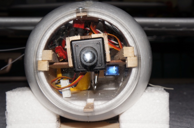
The 1st flights good enough to get on video. It's extremely unstable, but there is hope. The MPU9150 was the only way to get the sensors small enough. It might also be the smallest thing currently flown by a computer, anywhere in the world.


There was some chance noisy stick voltages were making it unstable, but the oscilloscope showed the noise was down near 20mV while flying deflection was near 500mV in the pitch & 100mV in the roll. The Y position has more error because the camera can't sense depth.
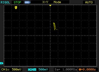
roll & pitch sticks while flying

roll & pitch sticks while flying
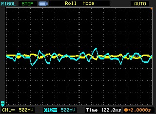
roll & pitch sticks while flying
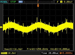
inactive stick noise

changing stick by 0.01


After a flimsy hot gluing of the board on top, the MPU9150 gave drastically improved results over having 1 board for a magnetometer under the battery & a 2nd board on top for a gyro. There's still a bit of error because the board isn't perfectly flat, but it manages to recover. The current or the flexing of having it under the battery was a problem.
There was 1 source file for the MPU9150 on http://permalink.gmane.org/gmane.linux.kernel.iio/4339, revealing undocumented register REG_YGOFFS_TC. He never uploaded the header files.
With the full Marcy 3 software & the crystal, the MPU9150 only reads at 80Hz.

A wishful crystal to get the PIC as fast as possible added some more size. If the PIC does nothing else, it can get 140 readings of all 9 sensors per second. Without the crystal, it can get 80 hz. 50Hz is probably enough for the application.
Being the low end PIC that it is, only software I2C was justified. If it was concerned with the full attitude stabilization, it would need hardware I2C for the gyro/accel part. The trend is now to use STM32F ARMs for even these nano quads.


Took some doing to override the stick voltages.
Automating the Ladybird is a big deal since it requires many many voltages, leading to a pile of LM317's on the verge of cracked resistor circuit board incineration. Mercifully, the remote control has reversible directions, eliminating the need to make a new table of stick directions or require multiple steps to initialize the stick voltages.
Randy posted a great tutorial on using ArduCopter tlogs. Thanks Randy!
