The new version of the cool IEEE Robots app for the iPad now includes ArduCopter!
All Posts (14049)
Sort by
After a year of having purchased the camera FH 10 with 10x zoom, the first experiences were poor due to the lack of a system of stabilization.
then decided dusting the camera again and stabilize with AMP 2.5. using the PAN and TIL my RVJET, to install it sideways. in my skywalker 1900. the camera has stabilization in the ROLL axis, the flight height is 300 meters and the loiter radius is 200 meters.
https://www.youtube.com/watch?v=UrPrqO9uFew&feature=c4-overview&list=UUVoTd1B5K8AEVzY4R0vIqJQ
Mississauga, Ont., businessman Dany Thivierge, right, has established himself as a go-to man for hobbyists in need of drone parts and know-how. (Evan Mitsui/CBC)
Hi guys, pretty happy about that one!
Last week we filmed with CBC Evan Mitsui to get a good view of how the UAV hobby side was doing.
We spend a good half day showing off technologie that here we now take for granted but that the vast majority of the the non initiate people have a hard time grasping. We went flying (couldn't get the Hexa to work... I swear this thing has severe stage fright syndrome, when it's time to shopw off it refuses!) but we had fun with a Quad and recorded everything on the entry level DJI Phantom.
Was a very nice day and we had a blast.
Check the second part of the interview to see me with Yuri a friend/customer with a very DIY setup.
http://www.cbc.ca/news/canada/story/2013/07/10/f-canadas-commcerial-uav-drones-laws.html
OVERVIEW:
 Ecilop Eco is a quadrocopter developed specially for begginers in aerial photography and video. The wood frame absorbs vibrations and does not pass them to the camera. It is the first commercial model which is using RoControl technology for camera rotation and stabilization controlling. Two axle camera gimbal is integrated into the model. The camera gimbal is attached with a single screw, so you can make test flights without a camera. We have not set the kit with motors, controllers, screws and other, so you have the freedom to choose them. You can have minimal experience in modeling to assemble the Ecilop Eco model yourself.
FEATURES:
 Multicopter swaying does not affect the camera, since the camera rotates leaning against the air and not the multicopter frame. Other camera gimbal types using the frame try to quickly stabilize the camera when tilting takes place, whileEcilop stabilization does that inertially. A lightweight wood frame will not cause a lot of damage in case of crash. Small lightweight propellers cannot cause serious injuries. If the drone falls from the height of several meters, the frame is likely to remain intact. Quick repair of the wood construction is possible in field conditions using super glue. The frame of the drone can be spray-painted into any color. Two people can simultaneously control the drone to ensure professional shooting quality. In the “heading hold” gyroscope mode, the camera will not tilt following an erroneous signal from accelerometers (the second operator can take care of smooth tilting). Both optical and inertial horizon sensors can be used for automatic camera stabilization. Drone elements never appear within the camera’s FOV and do not appear in footage (without a fish-eye lens). The compact drone can quickly maneuver and fly through narrow passages. A lightweight drone does not need heavy and expensive batteries.
Sample Onboard Video
Photo Gallery:
Like a Bixler, but bigger and with a cool nose dome for a forward-facing camera. $120, now available from HobbyKing.
Details:
The Sky Eye is a large plug and fly glider designed for the FPV pilot who is looking for all the benefits of a larger model that is also fast to get into the air and won't break the bank!Make no mistake, the Sky Eye is a biggie! That said, it is also really practical and features a 2pc plug in wing and huge magnetic canopy for easy camera and Lipo access. Being a plug and fly model, the Sky Eye is really quick to assemble, the heavy duty mini servo's are all pre-installed, as is the powerful 35mm brushless out-runner motor and ESC, in fact setting up your camera in the supplied transparent camera dome is going to be the longest job of the build!As the old saying goes, the bigger they are, the better they fly and with a 2 metre span, the Sky Eye provides a high lift, stable and virtually un-stallable camera & FPV platform thanks to it's generous wing area and effective pre-installed flaps. The powerful brushless outrunner and 8" prop combo offer an excellent climb rate while the effectively sized four channel control surfaces offer absolute control at all speeds. This fantastic model offers a fun and easy to fly glider and FPV/Camera platform in a simple & fast to build format that is totally affordable and perfect for pilots of every ability, the Sky Eye offers something unique and familiar rolled into one great priced package!Features:• Tough EPO Construction• Plug and Fly Format, Simply add Battery and Reciever!• Large Size Ideal for a Stable Flying in a Variety of Weather Conditions• Unique Nose Mounted Transparent Camera Dome• Pre-Installed Landing Wheel• Pre-Installed Flaps• Large Magnetic Canopy• Plug In 2pc Wing for Easy Transport• Powerful 35mm Brushless Outrunner• Large Payload Capability• Large CF wing TubeSpecs:Wingspan: 2000mmLength: 1100mmWeight: 1350gWing Area: 46.3dm2Wing Loading: 29.2g/dm2Servo: 6 x Mini 17gESC: 30A w/BECMotor: 3536 Brushless Outrunner 900kvProp: 8x6
Its in the way that you use it. I was able to make these aerial shots at my parents farm using a $60 glorified toy quad, and a keychain camera. The source for this was actually a panning video stitched into a single shot by Microsoft ICE (image composite editor). Not bad for a less than a hundred dollar setup, and free software, I think.
...but there's a snag. Right at the end of the build too - extremely annoying. More on that later.
First, apologies for the photo's my main light is bust, and I'm only using an iphone!
This post is a look at what I did with *NO* external compass.
1. Reversed the screws and bolts. Supposedly, the end of the screw causes more interference than the head. This could all be complete rubbish, but since it was in bits, I did it anyway. Now the heads are what's closest to APM.
2. Replaced the 8mm anti-vibe stand offs with a 1cm metal one. Doesn't sound like much, but it's all I had lying around that came with the kit. The good news is, I recon you can get 2cm stand off in there, while preserving the cage. and dome.
3. Twisted the power wired for the ESC's once. That's all I could do given the short cable lengths.
4. Re-did the PDB. It's bigger, and the soldering is much improved. I also took the opportunity to wire in an extra JST.
And that's it for now. Was hoping to run the compassmot in this base config...BUT THE DAMNED ESC'S ARE REFUSING TO SET THEIR END POINTS!!!! Ultra annoying, given the rebuld is complete, the motors are all running and in the correct CW/CCW fashion, everything...but fails to set the end points. Last time I had to take the whole thing apart, and only then did they spring back into life. Sequence after boot up is:
- two beeps
- the calibration scale
- one beep
(throttle down)
- one beep (throttle up....nothing....throttle to max...error tones)
Doesn't matter if you wait for two beeps or one - it still errors out. These are t-motor 30A OPTO PRO's and appear to be running normally apart from this. Dodgy motor maybe? One is making some low vibrations at mid stick with no props.
Anyway - I was request to post details about the rig. Well, here it is:
That's an RCtimer gimbal but with an alexmos. The flight battery is a 10900mAh from maxamps.
Spektrum RC mounted on port side. Includes telemetry. And APM obviously, mounted on double moongel corners.
Fatshark 5.8 tx + bluebeam. Also in shot is 0.1 minimOSD from jdrones. It's not working right though (see forum post) with gopro as the source. Smearas white behind the text (text is clear and sharp, as is image)
Where the fun will take place. A DJI style riser has been fitted - just waiting for my 30cm cable now for the external mag. GPS will also be replace by GPS/compass combo from 3DR, but the old one stays in place for now. The port and starboard pylons have been extended outward to their maximum as well. I should have huge distance between the compass and APM after this is complete!
Underneath is a Turnigy 4-in-1 BEC and the battery for the FPV. Will probably power the FPV camera (have decided to avoid the GoPro, after the current problems). Once I find a suitable Y cable for the balancer port, I can ditch this battery and save 100g.
The Braincube flightlights controller v5 and the electronics battery (on a 3DR PM). It's chunky and heavy, but the power the lights give out is incredible. No orientation issues, even in bright sunlight, so it's worth the weight penalty.
So...almost ready to test. Just gotta work out if I can solve my ESC problem without resorting to a complete disassemble again!
http://new.livestream.com/accounts/3669891/events/2245360
Click the link above to watch our compete team in the 2013 AUVSI Roboboat Competition and hopefully launch our quadrotor from the boat. The quadrotor is an aerotestra platform that has been provided by Sean Headrick (Profile) so a special thanks to him. Our team should be up at 3:30pm EST.
Currently a GoPro 3 is static mounted to my Neo 660 Hex Copter and it takes pretty nice video, but the video is pretty wild and jerky due to the maneuverability of the copter. So a brushless camera gimbal is in the works. The SimpleBGC Controller for the gimbal just arrived from Aerial Pixels and had it's first light today.
The board version from Aerial Pixels include both the FTDI and a USB interface for programming the controller. The USB fired right up without loading any additional drivers when plugged into my Windows 8 box probably since it was already loaded from another project, but the driver is available from the Aerial Pixels support page as well.
The SimpleBGC GUI did not connect to the controller at first because the GUI has newer than the firmware on the controller. That was easily fixed with the instructions from the Aerial Pixels support page, including the very helpful note that the flash loader XLoader displays a failure message on loading the new firmware even though it succeeds.
Just waiting on the gimbal mount now.
I created an Excel spreadsheet to analyze the telemetry data during the flight testing, and have discovered some pretty interesting correlations between altitude and RSSI, throttle settings and cruise speed, cruise speed and mAh/km, etc. This by no means replaces the graphing functionality the Mission Planner has, but its a start into some of the specific analysis I'll need to capture as I prepare for the USA trip.
USA Trip Details: http://www.mygeekshow.com/usatrip/
We got recently some nice shots that we would like to share while flying multi-rotors at high altitude (approx 3000 meters) in the amazing natural theater given by the Alps. The video shows the preliminary steps of our new SHERPA Project (www.sherpa-project.eu) which is focusing on the application of robotics technology (including of course aerial robotics) in the Alpine rescue scenario.
I really believe that we will get some really interesting results to share with the UAV amateur community.
To this end, I would like also to show you some results obtained with our former project, AIRobots (www.airobots.eu), which was focusing on designing and controlling innovative aerial robots able to physically interact with the surrounding environment.
The ideal goal was to design a sort of "flying-hand", and as you can see from some of our videos we got really some nice toys :-)
See you all very soon and thanks to all of you for the many inspiring ideas that are driving our research!
Roberto
(member of the SHERPA and AIRobots project)
http://intuitiveaerial.com/home/2013/7/14/oculus-fpv-first-flight
First flight of our Oculus Rift FPV system!
This system is completely digital. A laptop in the air compresses the video from the two cameras in realtime and sends them over 802.11n (2.4 GHz) down to the laptop on the ground.
Latency is around 120 ms - fully usable for flying!
Range is 50-100 m using built-in wifi-cards in laptops. We will increase this by using external APs. Ranges for e.g. Ubiquiti-systems are quoted as several km - using legal frequencies and power levels. When out of range and then back the reconnection is instant (no "connection broken, reconnecting...").
There is a huge difference between this and an analogue FPV system. The all-digital design means realtime HD video from multiple (not limited to 2) cameras can be broadcasted and received. The received images are then combined into a view-sphere which can then be viewed in a below-25-ms latency loop between ground computer and the Rift. Jonathan is working on the code to let the imu of the Rift determine what is seen.
This project is an R&D effort from Intuitive Aerial. We have dreamed of this system since before we heard of the Oculus Rift. It is like a piece of science fiction that just came true. We have plans for how we can go from software running on laptops to small specific-purpose units so no computer is needed (FPGA-based compression and encode, lower-latency camera connection, possibly integrate cameras on pcb). Such units would also be useful for regular FPV and would offer HD resolutions and wifi interoperability. Let us know if you want this to happen - right now Jonathan is the only one working on this, as his master's thesis project :)
I have written a tutorial on how to program your own AutoPilot/Flight Controller from scratch using an arduino/ArduPilot/RaspberryPi. The tutorial will walk you through everything from reading the RC radio and controlling the motors through to how the PIDs are stacked on top of each other to get stable flight. Information on how to do this is quite hard to find on the Internet, so I hope this article will make the world of flight controllers more accessible and encourage more people to contribute to ArduCopter.
You can find the full article here:
http://ghowen.me/build-your-own-quadcopter-autopilot/
and a video of the code from the article in action (you can download the code and try it on your APM - it'll behave like a KK board):
Note: the code actually flies better than the video demonstrates - my PID settings weren't optimally tuned!
This is the second chapter in my quest to build a flying machine. If this is your first time in joining me in my project of getting a flying machine in the air, I’d encourage you to have a look at Part 1.
In the first installment in this mini series, I spoke about how difficult it’s been to get in to the world of flying copters, due a many acronyms, assumed knowledge and the complexity of the options available.
As I sit here on a return flight to where I am currently living in Brisbane about to down some complimentary coffee and listening to music on the free headphones given to me for the in-flight entertainment, I’m getting the chance to finally reflect on some of the challenges and discoveries I had when building upon my new found hobby.
I had ordered the 3DRobotics hexacopter with the full electronic kit and was super excited when it ordered no more than 5 days later – from the USA. I know that there have been several comments on my last post made about Hobby King as a supplier of equipment. In good faith I had also ordered parts from them too, expecting parts to be delivered within a few weeks of each other at the most. On a side note, I’ve almost given up on expecting the parts from them in time for when I initially needed them – before this week.
I was at my normal job when the box from 3DR arrived. If you are like me, when you go to a shop, usually the box will get opened in the car – this happened again. I’m like a kid who can’t wait to open his presents at Christmas.
On a side note, just beware that if you use a P.O. Box to accept deliveries that some couriers may have trouble with delivery. Fortunately the courier rang me asking for a local physical delivery address.
So, as the box arrived and I open it up, I quickly discovered there were no instructions in the box, or where to directly find them, and no paperwork saying ‘Congratulations on your purchase, we hope you enjoy flying it. You’ll find more information at X etc…”. I was a little surprised at this. The top of the box had the order and contents/packing slip on the top though.
Because this is a community project that I purchased, I’ll let it slide. Even though projects are community based, I know that model designs change and are regularly improved over time.
To the team at 3DR, here’s an idea. When you make and release versions of the hexacopters, are you keeping an archive of the documentation online for each version of the models that are released? I know this happens with the AurdoPilot board, but what about the frames and kits available too, and including basic documentation?
I’m sure it’s not too hard to keep track of the changes and refinements that go along with the manufacturing.
Why the previous suggestion? Well, The first thing I had to do was find the instructions. This took a little searching to do, because even though 3DR are making it and there are “link placeholders” on their site on the actual product pages they are selling, there are actually no links. (This has since changed – well done.) I needed the specific PDF file which laid out quite well the construction of how to build the new frame. There were random links in the forums, and the Wiki but not easily found.
This is the current link of the 3DR hexacopter instructions.
I also found the photos and step by step instructions from the UK Arducopter site very helpful too.
Upon getting these instructions I printed them out in colour was able to set to work.
My coffee table at home was covered in bits of aluminum, cables, plastic, cool little blue motors and some things called ESCs.
As a child I enjoyed playing with Lego and Meccano, so assembling this new contraption wasn’t too hard to do and as a newbie, I was able to easily do it in under a standard movie time.
The manual made it very easy to understand what went where and how all of the hardware joined together. This was the fun and easy part.
I did have one slight problem and that was because I was missing a little screw to keep one of the motors on the arms. I made a note of which one it was and did it up slightly tighter than the others. I searched everywhere and was extremely careful not to lose any part. All I can put it down to is either quality control and someone not counting to 12, or a screw falling out of the bag there were packaged in because of an air hole and they were lost in transport. It certainly wasn’t the end of the world, so I didn’t really worry too much, and up until this time I haven’t raised it with 3DR – I have since bought a packet of m3 6mm screws though as spares for the legs and other parts for (*cough* when) if I break the copter.
The next part after the initial frame construction was the electronics of the copter – this is where having the laptop on hand helped immensely.
Construction
The manual gave step-by-step instructions for the frame and the distribution board (which was thankfully already assembled), but when it came to the electronics, the manual basically said (and I’m paraphrasing here) “Connect the electronics and you are ready to fly”. What the?
I had my AurduPilot controller (which is known as the APM) with lots of plugs available, and also a distribution board available with many wires. Naturally you can see which plugs go where, however because I’m a person that likes to pull things apart to see how they work and put them back together again, it’s taught me a thing or too.
Even when I was working on acid etched circuit boards in my early days in high school I could easily understand how and where power flowed on circuit boards. Even looking at PCBs you can see the copper lines and how circuits join with each other.
The next part threw me. The 3DR distribution power-board totally confused me. It is painted black and has 7 power plugs coming off it. It didn’t make sense to me as to how it was wired up. As I couldn’t see the paths of the electronics, I wasn’t sure of how this thing was truly wired up. I like to ask questions, find out how things work. Taking things at face value sometimes is hard for me until I’ve got a good understanding of a product/item. My old multimeter had died and so I was stuck.
I did however manage to find a schematic of the board online. (http://stuff.storediydrones.com/Hex_Power_Distribution_Board.zip)
Yes! My research was paying off. Next to find an opensource tool read the strange file. Once I could see the wiring of the board on the screen, I was set and good to go. (http://www.cadsoftusa.com/download-eagle/)
As it turns out, according to the schematic diagram of the board, this is how's it's connected under the paint.
http://store.3drobotics.com/products/hexacopter-power-distribution-...
Before I'd seem the schematic diagram, I was VERY tempted to start doing extra soldering of all the pins, but also for the power plugs too. The board itself is painted, and so at the time - it just didn't make sense.
Oddly enough, I still bought a $12 multimeter and double-checked all the plugs.
To most people who have created a copter of some sort, most of this is all second nature, but when you’ve never built anything like this, you want to make sure you get it right before you start powering things up – just in case you short circuit something. I’m sure you’ve blown a fuse, popped a diode or connected batteries the wrong way. When you pay good money for a hexacopter, this is the last thing you want to do.
After studying many images and designs of other people’s copters, I was able to finally connect my system together on the table to see how it would look before it was to be fully installed in the copter itself. Everything looked good. GPS plugged in, ESCs in the right place, loose wires everywhere and so on.
I laid everything out to get a good idea too of how the configuration was going to work as well.
The pictures shown are basically how the cables go together.
In Part 1 of this blog series, you'll remember from the design image how it all goes together. This the actual of how it goes together.
As mentioned before, my order from Hobby King hadn’t arrived and so I had a kit that was half built. I couldn’t do anything else and it was getting to me. I had no battery, or radio system to use the copter. This was really frustrating me – having a half built machine sitting there being unable to progress further because of a lack of parts.
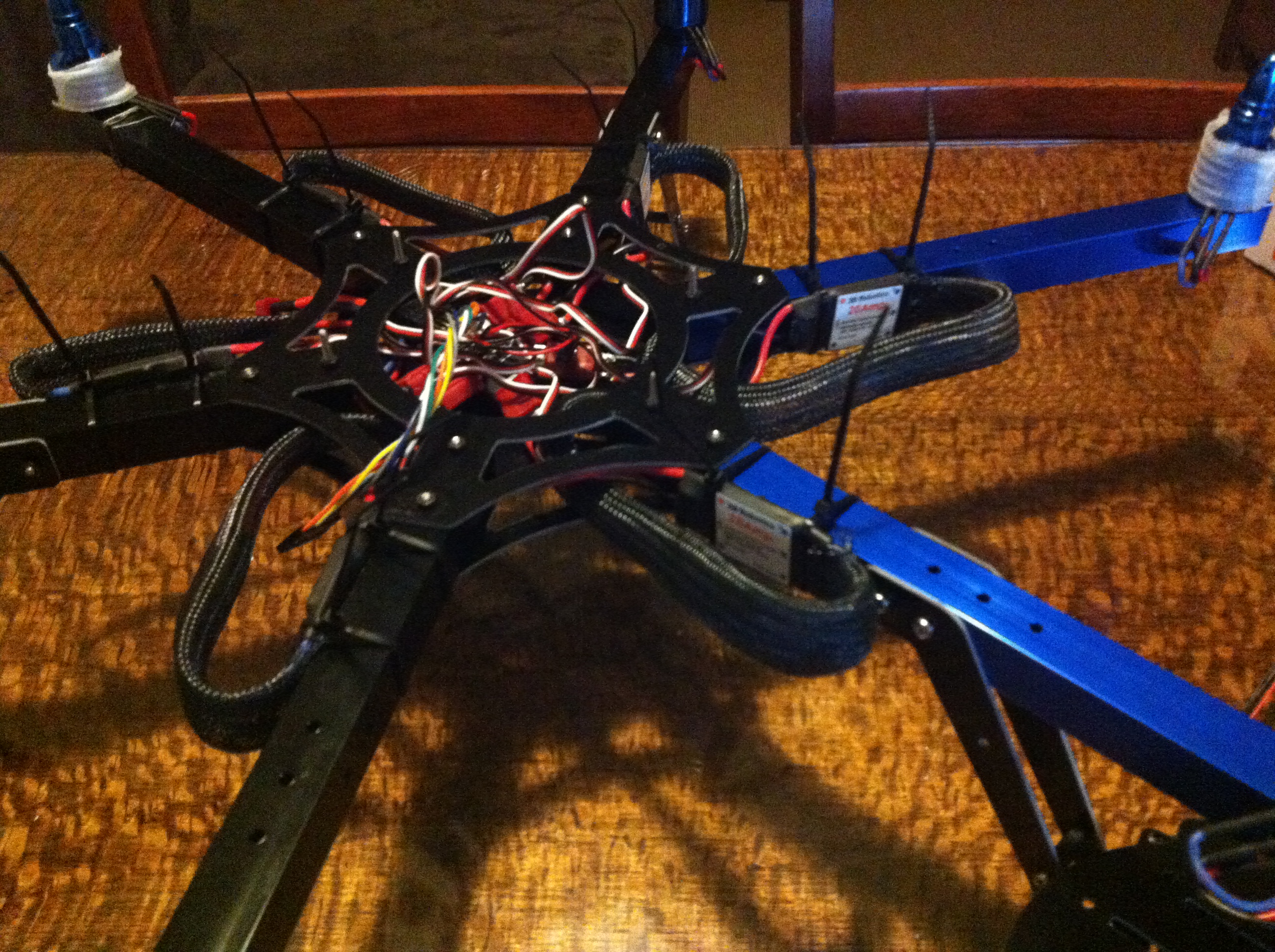 Electronics nearly installed.
It was at that stage that I had it suggested to me to try a local hobby shop and see what was available. In all honesty I hadn’t thought about that option – for two reasons. Firstly, this was a completely new field to me and so I didn’t/don’t know of many/any people doing it as so had assumed it to being a super niche market. Secondly, I often find myself going to shops and asking for items that are considered ‘specialty’ items and so walk out empty handed. This happened a few years ago when I wanted a shoulder mount/frame for my DSLR and went to one of the biggest camera places where I live. They didn’t have any stock or parts. So, what does one do in that instance? You go online and wait weeks… This was where I thought I was.
 As it turns out, radio controlled gear (although as slightly specialist as it is) is reasonably common and not too hard to get hold of. So, off I went to the local R/C hobby shop. I grabbed one of the cheapest but full featured radio control units available a Futaba F8 unit – which includes a receiver, and it also runs on AA batteries; a big bonus. (Some transmitters have interchangeable transmitter packs for various frequencies and things).
When I had these new components with me and a big kid grin on my face and a hole in my wallet (because I’d just paid for a radio and batteries a second time – thanks HK), I was able to continue the build process and get things going properly.
It had taken me at least a few weeks to get to this stage, so I made minor tweaks to the initial and suggested look. I added some black braided plastic to conceal the wires on the six arms.
As soon as I brought the batteries home, I discovered I had a problem. I had initially ordered the wrong part. My battery had a T (Deans) connector on it. My power module unit from 3DR had an XT60 connector on it. Fortunately for me, a gentleman on YouTube has made 4 videos outlining various phases in the configuration of how the APM works and what goes where. It’s a good thing I’d watched them all and remembered about the little jumper pin video, as this was what saved my day. (https://www.youtube.com/watch?v=TFCmUuvcH04)
This basically meant I had to use the little jumper, because instead of using the 3DR power module, I'm now getting power from the ESCs to the APM. It's not a big issue, but just means the APM can't monitor the battery power and do an emergency landing if it runs out of juice.
The other videos in this mini series are also very good to give you enough information as well - Part 1, Part 2, Part 3 and Part 4.
One of the things I also did while waiting for parts and the construction phase was connecting the APM to my computer and loading the firmware required. After downloading the Mission Planner software, it was very easy to put the Hexacopter software on. There are plenty of tutorials out there about how to do this. I did however get excited to see the live telemetry data and the GPS signals coming through on my computer while the GPS module was connected. This was one of the main reasons for going down this OpenSource path.
When trawling through the wiki pages, also note that you are in the ArduCopter pages. The ArduPlane wiki pages are very quickly linked too as well and it's easy to mix up where you are. Most of the information is relevant, but at times it can be slightly conflicting.
For those wondering about how to connect the transmitter and other things, it's very easy.
 The connections on paper.
 Nearly finished.
 What the radio transmitter IN connections look like up close.
 Completed!
One thing you may notice is how I ended up connecting the ESCs to the APM. I went directly from and skipped using the distribution board because a few of the connections had broken and after doing a couple of tests with my multimeter, I wasn't totally satisfied with how it was working. It was easier to remove the soldered cables and go direct.
Thanks for reading. There is still more to come however. Stay tuned...
Hello everyone,
I am super excited to be back on the board and ready to play with my new incoming APM! I have had some experience with the DJI Naza but I always felt that I was missing out on something. So here I am today about to begin my build.
Here's the build:
APM 2.6 w/ external compass and uBlox GPS (Awaiting Shipping)
3DR Telemetry Kit (Awaiting Shipping)
4x RCTimer HP-2212 1000 kV Motors
4x RCTimer Carbon Fibre 9x4.7 Props
I picked the TBS Discovery for a bunch of reasons but I am really concerned about its integrated PCD bottom plate causing havoc with the APM. Does anyone have any suggestions?
I've searched far and wide on the web for similar APM TBS Discovery setups but I have been unable to find any photos or explanations about how to best connect & place everything. So if anyone has similar experience please chime in.
Eventually, I want to FPV but I need to hide some more cash away from the wife before I do that. So in the meantime, I'm looking forward to tinkering with the APM and playing the telemetry.
I know everyone has a lot of experience here so please help me out with suggestions.
.... Sooooooo excited!
Hello,
(Similar, previous blog posts: January 2013; February 2013.)
You may be interested in THIS page that we made after reviewing all 243 blog posts of March 2013. We focused on unmanned aerial-vehicle systems (UAS) and unmanned aerial vehicles (UAV) to identify:
- the posts that are closely related to a defined term or topic;
- a list of sources of components, systems or services, as named in the posts;
- other kinds of information from across the posts.
Next we will review the 226 blog posts of April 2013, followed by the remaining months of 2013 blog posts.
Because of the large number of links, the page may load slower than other pages on the DroneSpeak website.
- John (D.) Githens and Doug (R.D.) Starwalt
(DroneSpeak Administration)
Slate posts a podcast of the first lecture at the new Drone U, "a public education platform focused on the social, legal, and philosophical implications of drone technology" conducted in partnership with the New America Foundation. The first lecture is by P.W. Singer, director of the Center for 21st Century Security and Intelligence at the Brookings Institution.
Here's Slate's summary:
As Singer discusses, the current debate around drones is comparable to the initial challenges posed by the introduction of the car in 1900. This technology brought strange new questions, such as how to protect people from them. The first fine for “speeding” came just a few years later, when a man was arrested for endangering the lives and property of pedestrians in downtown Jacksonville, Fla. He had exceeded the 6 mile per hour speed limit. “Horseless carriages” were a technology that once seemed alien much like unmanned aerial systems do today.
When we think about technologies like the Predator or Packbot, we need to remember that they are just the first generation—the Model T Fords and Wright Flyers. We are still at the “horseless” stage of this technology. Describing these technologies as “unmanned system” means we are focused on what they are not, rather than wrestling with what they truly are.
What the opening of the civilian airspace will do to robotics is akin to what the Internet did to desktop computing. Revolutionary technologies force us to ask new questions about what is possible and consider things that weren’t conceivable a generation before. But they also force us to relook at what is proper. They raise issues of right and wrong that we didn’t have to wrestle with before. With robotics, issues on the technical side may ultimately be much easier to resolve than dilemmas that emerge from our human use of them.
You naughty scamps...you see a nice pair of legs, and the first thing you think about is what's between them. Pervs...:-D
July 12, 2013 By
Imagine a quadcopter hovering above a payload – a can of beans, perhaps. The ‘copter descends onto the payload, activates an electromagnet, and flies away with a hobo’s dinner. Right now, this is a bit of an impossibility. A normal electromagnet that powerful would consume an amazing amount of power, something quads don’t usually have in abundance. With the OpenGrab project, the dream of a remote-controlled skycrane is within reach, thanks to some very clever applications of magnetics.
The tech behind the OpenGrab is an electro-permanent magnet, basically an electromagnet you can turn on and off, but doesn’t require any power to stay on. OpenGrab was heavily influenced by a PhD thesis aimed at using these devices for self-assembling buildings.
This project had a very successful Kickstarter campaign and has seen some great progress in the project. While beer doesn’t come in steel cans anymore, we can imagine a whole lot of really cool applications for this tech from infuriating electronic puzzles to some very cool remote sensing applications.
Filed under: hardware