All Posts (11086)

Sort by

BEAM navigation

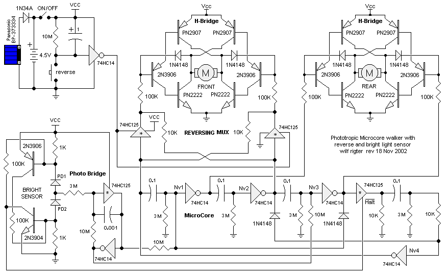
Phototropic_2m_walker.gif

This is the circuit for a phototropic walking robot insect which follows light.
It's based on M.Tilden's work, BEAM robotics: it's about analog control circuits (microcores) that simulate neural and nervous networks present in the in the real insects' spinal cord; these react to external stimuli in a robust and very reliable way. Many other circuits have been drawn to do things like follow light, sense obstacles and reverse motors.
Of course this works just for walkers for the moment.

here comes my project: a BEAM autopilot!
It will be based on conversion of digital data coming from sensors, GPS to analog current levels, that will be inputted to control circuitries like the one above. The outputs will then be reconverted to digital for actuating servos and so on. I haven't still drawn nor calculated anything.

This is just a newborn concept, now I'd like to hear opinions of feasibility from experts in electronics I'm such a stinky newbie!

Thanks to everyone who will give me some thoughts!!
Read more…
3D Robotics

Book review: Skunk Works

I just finished a terrific book that should be an inspiration to aircraft engineers everywhere. It's called Skunk Works, and it's an inside story of the peak years of Lockheed's now-famous secret development lab, which created the U2, SR-71, and Stealth Fighter. Although first published in 1994, it's still a totally gripping read, full of anecdotes of Cold War air battles and engineering heroics. Think "Soul of A New Machine" but about spy planes. I couldn't put it down.

They also created the first reconnaissance UAV, a jet-powered Mach 3+ drone called the D-21 that was launched from a B52 and designed to overfly Russia or China, dropping its film canister by parachute to be recovered before self destructing. This was before GPS, so the drone used a sophisticated star-tracker for navigation. Although it flew five missions over China, problems with the film recovery process led it to be cancelled.

A couple cool tidbits: the big breakthrough on stealth was the discovery (from an obscure Russian scientific paper) that the radar signature of a flat object was the same (and small) regardless of its size. Thus the faceted shape of the Stealth Fighter, shown on the cover at right. The fact that computers in the 1970s could only calculate shapes with big polygons also contributed to its distinctive shape.

It's co-written by Ben Rich, the chief of the lab for much of that period. Highly recommended!


Here's the Publisher's Weekly description:

"Lockheed's Advanced Development Project has set standards for the aerospace industry for half a century. Under its presiding genius,
Clarence "Kelly" Johnson, the Skunk Works produced America's first jet
fighter, the world's most successful spy plane (U-2), the first
three-times-the-speed-of-sound surveillance aircraft and the F-117A
stealth fighter. Rich was Johnson's right-hand man and succeeded him as
director in 1975, retiring in 1990. In an entertaining style, the
authors describe Johnson's tyrannical managerial style, his thorny but
productive relationship with the Air Force and the stealth-technology
breakthrough that revolutionized military aviation. Writing with
freelancer Jonas, Rich also recounts Skunk Works' failures, including
experiments with liquid hydrogen as a propellant and spy-drone flights
over China's remote nuclear test facilities. He has much to say about
the Defense Department bureaucracy and warns, "Everyone in the defense
industry knows that bureaucratic regulations, controls, and paperwork
are at critical mass... and... in danger of destroying the entire
system." This is a significant book for those interested in aerospace
research and development."
Read more…
Moderator

Dear Friends,
this is the first video of Java GS by Riccardo Ferrari (Fox Team) in action.
Java GS using RPC Server architecture implemented in Arducopter Redfox74 branch.
This is new approach to Groundstation for people that prefer completly opensource architecture instead to use labview. In the next revision of Arducopter i think that we implement this code as experimental , activable by DEFINE .
Regards
Roberto N.
FoxTeam : www.virtualrobotix.com


Read more…

Around the world with no fuel!

Hi Guy's,

Way off topic but.... How cool is this!

These guys have built a solar plane that has the potential to stay up for ever with no fuel!!

The will attempt to fly it through the night in the next week or so.

Here is a little video from their YouTube channel. Cheers!

Read more…

This week in aerospace


Monterey flights were pre flighted but the fog never cleared. Then attempted a failed flight over Tomales Bay in which we discovered 2 years of vectoring motors to aim the camera had worked the mounting tape completely loose. Monterey would have been a disaster in that case.

Almost time to invest the $30 in an arducopter. Wait long enough & commercial technology eventually can take over what only custom systems did years ago. Would prefer a 32 bit processor on the smallest board possible, without all the extra stuff or fragile hirose connectors.


The trick with the Vika 1 airframe is real cheap crashes. All the parts are easy to make with hand tools. $10 of wood lasts 1 year of crashes. Who knows what CNC aluminum & landing gear would cost.


Did snap a video of the moon over the valley during a mounting tape test flight. It seems the wind is always going to tilt the propellers slightly.


MediaTek didn't materialize. Wasn't optimistic about it from the beginning. In the interview could tell #1 they were looking for someone with a formal education in computer science & not a jack engineer. #2 they obviously knew someone else & we were just a sales pitch from a recruiter.

However, probably going to start another job in 1 week not in aerospace mind you. Vacation fail.


Read more…

Got any great ideas of how to use a flexible board Arduino - these guys are making "a few for inspiration" and sound like they are willing to share their new toys with people with awesome ideas!!

http://www.seeedstudio.com/blog/2010/06/29/seeeduino-film-maybe-the-first-arduino-board-on-fpc/

Read more…


I just thought I'd share a quick video (and picture.) This is a movie I made of a replay of a real flight a couple days ago. I collected the data remotely while the flight was in progress via a maxstream radio modem connection between the aircraft and the ground station. I saved the flight data on the ground station and then can replay it later in FlightGear. The display is a "glass cockpit" style display I'm just beginning to develop.

https://www.youtube.com/watch?v=vTZ7b-uiTgU

Disclaimer: I have really noisy inertial sensors rigged up at the moment, 10 bit ADC's, you'd laugh if I described my IMU calibration procedure, probably very non-optimally tuned kalman filter for these sensors, windy day (yeah that's it, blame it all on the wind) :-)

But the really cool stuff (I think) if you can look past some of the less smooth flying, is to see all the elements of a very dynamic system playing together in one view.

For instance: the altitude tape shows the current altitude and the target altitude (via a magenta altitude bug.) If you are below the target altitude, the VSI will show a target climb rate (or decent rate if you are too high.) The autopilot tries to match the target rate of climb by manipulating pitch. The green vbars show the target pitch angle. The yellow bird shows the actual pitch angle. The autopilot manipulates the elevator to try to achieve the target pitch angle ... and you can see all these elements working together to achieve the goal.

There is a similar process with route navigation. The system computes a target ground track heading using wgs84 based math. The target heading is marked by a magenta heading bug on the horizon heading tape. There is a white "V" indicator that floats on the horizon heading tape which indicates the ground track heading. The actual heading shown is "true" heading as computed by a 15-state kalman filter. (The filter converges to true heading, independent of wind, side slip, etc.) So the autopilot computes a target roll angle to try to line the white "V" ground track indicator up with the magenta heading bug. And finally the ailerons are manipulated to try to match the target roll angle. If you watch the video you can probably see that I need to increase the gains a bit on my ailerons (maybe the end point limits as well.) What do you think? You can see the actual roll angle often lags pretty far behind the target, and this leads to some excessive serpentining as the aircraft flies towards the target. But if I dial up the gains too much, I may start over reacting to my filter's attitude estimate correction jumps. I think there is a balancing act that needs to be made between tracking your targets quickly and accurately versus slowing things down a bit to help smooth out the flight.

Finally you can also watch airspeed. Right now the autopilot is configured to try to match the target airspeed by manipulating the throttle, so you can watch the throttle move up and down to try match airspeed. Of course as you fly the course and bank into turns, encounter up and down drafts, and work around filter estimation errors everything is changing all at once.

On the one hand, I would like to see much smoother and tighter control, but on the other hand I have to sit back in a bit of wonderment just watching all the pieces working together and doing what they are supposed to do.

I think this is evolving into a really powerful system for evaluating how well an autopilot system is tuned and how well it is tracking it's targets. If your PID gains are inducing oscillations, you can quickly see that. If the PID gains are too low, you can see the system react too slowly. You can see your controls throws max out at their preset limits (or not if that is the case.)

And for what it's worth, this display can also be fed from real-time telemetry data so you could optionally have this running during the flight ... I'm not sure why you'd want it ... maybe during the design and development phase or to impress your wife or girl friend.
Read more…
Developer

Ardupilot 2.6.2 Beta

3689358476?profile=original


This beta brings support for the new MediaTek GPS unit. The MTK works great and it's very light.

I've also added some bug fixes including:


  • Auto Trim - (on by default) When you enter any flight mode from Manual, you'll save your current trim values. Great for trimming your plane in the air.
  • FBW issues (turning too much in one direction) caused by incorrect or unset radio limit - fixed with new algorithm
  • Radio Mixing - lowered the mix value for more responsive sticks
Let me know if you have issues, and I'll update the release version.
Jason


Read more…
3D Robotics

I know, it's been messy. One Xbee adapter for the ground, another for the air. Why can't one Xbee adapter do it all? Now it can! Jordi's really outdone himself on this one. The newest addition to the DIY Drones store: the ultimate all-in-one Xbee adpater--just $24.95. From the product description:


"

This is the most advanced and competitive XBee interface board you will find! It's breadboard compatible, has 4 status LED's (one selectable to display ASC or RSSI), built-in 3.3V power regulator, configuration solder jumpers and an unique feature that allows you set the device as Master or Slave FTDI mode with a simple slide of a switch!

In master mode you will be able to attach any USB FTDI cable/board and send/receive data like the rest of the average XBee adapters do (normal use mode), but if you slide the switch to "Slave mode" you will be able to attach the XtreamBee to any FTDI compatible device, like Arduinos, ArduIMU and Ardupilot's. So you only need two XtreamBee's, one master and other slave to create a both-ways wireless FTDI communication (or one XtreamBee set in "Slave Mode", if you already have another third party XBee adapter). You can even tweak the board to "wirelessly" emulate CTS and RTS signals. This board was under development for about 1 and 1/2 years! But finally after many failures I made it work with cheap/passive components. Great isn't it?

For more information please click here.

Features
-Includes 2 x 2mm female receptor headers to correctly place the XBee module.
-Includes 1 x right angle 6 position male pin headers.
-3.3V regulator build-in.
-ON Led, Tx/Rx Led's, ASC and RSSI Led (Jumper selectable).
-Master/Slave selector
-Solder jumper allow you to supply the board directly with 3.3V (Only recommended in Slave Mode).
-Breadboard compatible!
-Screw holes for easy mounting. "

(Xbee module not included)

Read more…
3D Robotics

Unboxing the Gaui 330X Quadcopter

[UPDATE: I've now flown this a bit. A few tips, which I learned the hard way:


1) Don't connect the green wire (gain) to your Rx. That disables all the onboard buttons and the little pot. Better to set these manually when you've first starting. Later, once you've got it flying well, this may be something you want to control from Tx, but not at the start.


2) Make sure you check the little addendum (if you've got the old manual, like me) about how to set the ESC curve. Make sure the green wire is unplugged and the gain is at zero, then power on the quad when your Tx throttle is at high, then bring the throttle down.


3) CA glue all the fiddly little plastic retaining rings. They fall off all the time and you'll end up leaving bits of this quad on the field]


Now that we're getting into the quadcopter business, I thought I should get a better feel for the competition. First up, the new Gaui 330X quadcopter that we wrote about here. At $400 it's in the same price range as ArduCopter, but it doesn't come with a full autopilot. It's just an airframe, motors/ESC and a 3-axis gyro unit (no accelerometers, so it's not an IMU). No GPS or any ability to program it--it's just an RC quad, not a UAV.


They say you can upgrade it to GPS navigation someday, but there's no clue how.


It comes very nicely packed in an surprisingly small and stylish box:


That the gyro unit at left and the four ESCs.


Here are all the parts. Lots of bolting bits together.


When you're done, it's supposed to look like this:


If you want to upgrade to a bigger body (plywood and fiberglass), you can:


Read more…
3D Robotics

Unboxing the Feiyu FY-3ZT IMU autopilot

As promised ("take one for the team") I bought one of the Feiyu FY-3ZT autopilots from Hooks at FPVFlying.com, and it arrived today.


I haven't had a chance to test it (the software only runs on Windows XP right now, and I don't have any XP boxes), but here are the unboxing photos:


The instructions don't look too bad for a Chinese product.


Here are the parts:


--The three boxes in the middle are the (top) IMU, (middle) Remote Adapter and (bottom) Autopilot controller. Only the IMU and the Autopilot go in the plane. The Remote Adapter is for the ground station.


--Hooks also threw in a 433mhz 500 mW long range modem (black modules at left). I have no idea if they're legal in the US!


--There is also an OSD module (FY-OSD); I'm not sure if that's part of the basic kit or Hooks just being generous to me again.


--The GPS module is one of those very small Locosys deals (MC-1513). I'm not a huge Locosys fan, but we'll see how this performs.


--And the thing with the two red Deans plugs looks like a power/current monitor.


--All the rest is all the necessary cables, antennas and mounting bits.


Of course I took the boxes apart. Each one has an AMR7 processor. The IMU has the usual 3-axis accelerometer, a 2-axis gyro and a 1-axis yaw gyro. The controller board has a absolute pressure sensor. All the markings on the chips are obscured with black varnish so I don't know what kind they are.


I've got to fly off to Europe again tomorrow (Paris this time), so I won't get a chance to start testing until next week.

Read more…
Developer
Progress report: The ArduPilot Mega v1.0 firmware has reached a flyable state!


There is a lot of work left to do before v1.0 is ready for its beta release, but things are progressing. At present STABILIZE and FLY_BY_WIRE_A are working well. Full 4 channel control has been implemented. On board data logging is really making me smile.

Jason Short and I are working closely together and working through the navigation parts of the code. This will probably take just a little longer than just one of us ironing it out, but will result in a better end result. The big change is that we are changing from an architecture that supports a navigating a series of waypoints to an architecture that supports executing a series of commands. This turns out to be a little more complicated than expected, but will allow for much more refined mission scripting.

WE NEED YOU: If you would make a good alpha tester we could really use your help. Both Jason and I have some limitations that won't allow us to test fly nearly as often as we would like. I will probably only be able to test fly 2-3 times in the next 3 weeks. Alpha testers need to work closely with us to test out particular functionality and feed data back to us. If you are interested please PM me!!

We hope to have a beta release by the end of July. If you are using the code prior to the beta release you can expect to find that the code in the repository is changing frequently and from one day to the next there may be sweeping changes.
Read more…