All Posts (14048)

Sort by

APM works great with the X8

I present my X8 test with APM on board ... and modification for parachute landing ... the APM worked wonders with this wing, only I will have to make small adjustments to the PID's ..

I want to know if someone launched the camera tracking code? I'd like to try it in this wing X8 .... if anyone can help would greatly appreciate

regards

Jim

Read more…
3D Robotics

New free Xbee configurator

3689447608?profile=original

For those of you frustrated with Digi's X-CTU Xbee configuration software, there's now an alternative. Massimo Banzi, the Arduino team leader (who I'm having dinner with tonight in Rome!), reports:

Italian company “moltosenso” has released a free, cross-platform software that allows you to configure all the parameters of your XBee modules.

From the website:
moltosenso Network Manager™ IRON is the cross-platform answer for the users of Digi International® X-CTU™.
The same functionalities are now available on Microsoft Windows®, Linux® and Mac OS X™ operating systems.
Thanks to a snappy and totally free GUI, moltosenso Network Manager™ IRON is able to grant:
  • get/set of the parameters of Digi International® modules plugged to the PC, both in API and AT mode;
  • get/set of the parameters of Digi International® modules remotely addressable;
  • an effective graphic test for RSSI parameter, especially tailored for XBEE™ modules;
  • firmware upload (local and – where available – remote) for many supported Digi International® modules.

Download it and enjoy it!

Read more…

Turnigy Integrated PCB Micro-Quad

22607-1.jpg

This tiny  Micro-Quad features an integrated PCB frame, Simply bolt on the motors then solder your choice of 6amp ESC directly to the frame!

An integrated power distribution system is also included making for one of the neatest electronics installs around. All mounting hardware and frame components are included in the kit. All you will require to have this little monster in the air is four Turnigy T1811-2900kv motors, four 6Amp ESCs, a set of 5x3 Micro-quad props (2 Clock wise and 2 counter clockwise) an 800mah 2s 7.4v Lipoly battery, a HobbyKing Multi-rotor control board and your own transmitter and receiver (Tx/Rx).

Features:
Light weight design.
Integrated PCB for component installation.
Included a full set of frame and mounting hardware. 

Specifications:
Flying Weight: 145g (not including RX and battery)
Width: 250 mm
Height: 85 mm

Available from Hobbyking for US$ 14.99: http://www.hobbyking.com/hobbyking/store/uh_viewitem.asp?idproduct=22607

Read more…
Distributor

6267765.bin


Just a quick heads up, GPS might not be working so well over the next day!

"Keep your eyes on the northern sky Thursday night and be prepared for the  unexpected as a strong geomagnetic storm races from the sun toward Earth, says a  B.C.-based solar physicist.

The expected arrival Thursday of the strongest solar storm in six years could  affect power grids, airplane routes and space-based satellite navigation  systems, space weather experts said."

More information here


Regards


Martin.


Read more…

I have been working on a hexacopter for aerial videography and photography.   The hexacopter is equipped with a ArduPilot Mega with sonar, gps, magnetometer and a camera gimbal.  After hours of tuning, I got the Scout Hexa really dialed in.

I really happy with the stability of the Arducopter code.  Here is a video demonstrating some of the ArduPilot Mega's capabilities.  I am working on eliminating the aircrafts vibration to the camera.


Read more…
3D Robotics

3689447541?profile=original

We don't cover military drones here, but I'll make an exception for this fascinating accident report. We've all lost drones due to technical malfunctions, so we can sympathize with this. At least ours didn't cost $73 million.

From Defense Tech:

On August 11, 2011 Air Force ground controllers lost contact with one of the military’s most advanced — and expensive — drones, an EQ-4B Global Hawk as the jet flew high over Eastern Afghanistan.

Nine hours into an otherwise smooth communications relay mission using the Battlefield Airborne Communications Node (BACN), the plane was cruising at 51,000-feet above sea level 105 nautical miles northwest of Kandahar, Afghanistan — close to the border with Pakistan, in fact, the few news reports that emerged of the crash claim the jet actually went down inside Pakistan —   when a pilot from the 12th Reconnaissance Squadron out of Beale Air Force Base in California “lost all links with the payload,” according to a copy of the Air Force’s report on the incident that the service sent to DT. The pilot did everything he could to reestablish communications with the mammoth drone, but 25 seconds after losing communications, the plane began a high-speed fall to Earth. If plummeted so fast that “both wings and at least one of the lower aft fuselage fairings” were ripped off the jet as it fell. Three minutes later, the Global Hawk crashed into “remote, desert terrain approximately 4 nm from its last reported position and was destroyed,” reads the Air Force’s report. “the estimated loss is valued at 72.8 million.”

So, what caused this?

A single part — or Line Replaceable Unit, as the report calls it — came undone, interrupting the flow of electricity to the plane’s aileron and spoiler actuators — the tiny motors that control the movements of an aircraft’s flight control surfaces you know, the moving parts of the wings that control whether the plane climbs, dives, banks, rolls, etc. As expected, this disconnection rendered “the aircraft uncontrollable.”

(Critical parts that lose it like this one are called single points of failure, meaning that if these sometimes tiny and seemingly insignificant parts fail, the entire weapon system fails. Naturally, military equipment makers try o identify these and do all they can to ensure they won’t fail.)

Why did this single part become disconnected? “The board president also found, by a preponderance of the evidence, that the LRU [the critical part] installation methods were a contributing factor in the mishap,” reads the a summary of the report. Apparently, the screws holding the part in place weren’t tight enough and probably shook loose due to typical flight vibrations.

One other thing to note, the jet’s “avionics were not recovered from the crash site.” Let’s hope they were destroyed in the crash and the subsequent bombing of the wreckage by Air Force bombers and not scooped up by someone who could sell them to the Russians or Chinese.


Read the full reporthere:  

Read more…

Useful tips for log analysis

3689447516?profile=original

Hi all, I thought I'd do a little write up on how I tend to use the log analysis function of APMPlanner.

I don't claim to be very knowledgeable about coding and such, being more of a engineering type I tend to use the graphs to understand what the software is doing, rather then trying to understand by reading the code. This approach may be good for other beginners like me.


The first example is used to gain an understanding of what parameters are used in loiter:


Let's use an example of a flight that contained one failed attempt at loiter:


3689447493?profile=original 

 Graph the values from a NTUN line:  Long err, Lat err, nav lon, nav lat, Loiter lon I.

This will immediately identify the portion of the flight, where loiter mode was used. You can see that it begins around line 2000.

Zooming in on that part of the flight we get more detail:

3689447345?profile=original

RED and GREEN: How the copter is deviating from set position.

BLUE and PINK: how the copter is being commanded to move.

YELLOW: The state of the LOITER I TERM.


Here is the I term in more detail (YELLOW):

3689447527?profile=original 

You can see that the I wind-up has deviated from zero.

NOW COMES THE KICKER:

In the forum you can see people asking if X version of Arducopter uses NAV in the loiter or not. Obviously, you have to know this, if you're going to tune loiter properly.

Finding out is as easy as graphing a NAV I TERM instead of the LOITER I TERM:

3689447557?profile=originalIn this graph you can see that the NAV I TERM (YELLOW) wind-up does not deviate from zero,

hence this version does not use NAV terms or procedures for loiter.


A typical circling loiter:

This a typical circling loiter. The values being graphed are the same as in the last example, with no I term displayed.

3689447516?profile=original 


 You can see that the commanded pitch and roll BLUE and PINK are a diverging oscillation which is almost perfectly in phase - this accounts for the circling motion.

You can also see that the position errors are growing as a function of the increasing control commands by the autopilot. 


Anyway that's enough for today, I hope someone finds my amateurish contribution useful... 


Read more…

3689447398?profile=original

Hi all, sorry if this is a little off topic, but sometimes I need to cut foam cores to build planes.

So finally I decided to put together a little tool to calculate the position of the fixed position of the hot wire, in the case of one man work.

This way it is possible to cut foam cores alone, using only one airfoil template.

Here is a screenshot :

It should be correct, but if someone find something wrong, please tell me and I will fix it.

I thought this could be useful to some one, so here is it.

Documenti.zip

Best regards

Read more…
Moderator

3689447322?profile=originalSuperimposed volt/current graphs - 9x5 3-blade in red and 11x4.7 2-blade in blue


Further to my informal testing of 3S and 4S batteries with the same prop I did a test with 9x5 3-blade props (http://www.hobbyking.com/hobbyking/store/uh_viewItem.asp?idProduct=5248) and 11x4.7 2-blade props (APC SF 11x4.7).

Test procedure: using freshly charged batteries I took off and hovered at ~2m for 60 secs and then landed.

Quad specs:

APM2

KDA20-22L motors from Hobbyking

2 x Super Simple 25-30A ESC's from Hobbyking

2 x Hexfet 25A ESC's from Hobbyking (2 of 4 were DOA)

3S 3000mAh Turnigy 25C

X525 frame

Average values:

9x5

Va - 11.75V, Pa - 161.6W, Aa - 13.8A

11x4.7

Va - 11.89V, Pa - 150.2W, Aa - 12.7A

11x4.7 uses ~11W less power and ~1.1A less current on average for the 60 second flight than the 9x5

Full graphs below: 9x5 first.

3689447421?profile=original11x4.7

3689447455?profile=original

Read more…
3D Robotics

3689447312?profile=original

Ning, the hosting platform that DIY Drones uses, has just enabled badges! We've been asking for these for a long time so I'm thrilled. What that means is that administrators such as myself can now recognize members for their contributions and award them badges that reflect their skills and accomplishments. 

The badges are little image files that show up on the members profile picture, everywhere they appear, so you can see their status at a glance. 

We can create any kind of badge, both in word and image, and that reflects the qualities that we value most here. So which ones should we roll out? 

Here are some starting suggestions:

  • Moderator: one of the members with moderation powers here on the site
  • Developer: member of one of the official dev teams)
  • Maven: A recognized expert who is particularly helpful to other members. As an example, I've assigned the amazing Marco Robustini to this category, with a placeholder checkbox symbol. (We need better symbols, so I'll need people to submit suggestion badge images here, too)
  • T3 participant: Anybody who has entered in a T3 competition.
  • N00b Ninja: A member who is very patient and nice to n00bs ;-)

Any other suggestions?

Read more…

Marcy 2 bringup

marcy2_13.jpg
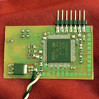
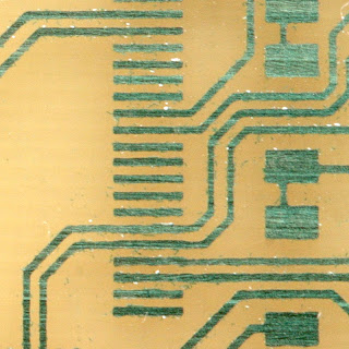
 Marcy 2 was our most complicated layout, ever.  Manely, the camera had 20 connections.  Let it etch for 32 minutes to make sure all the .5mm pins were cleared.  There were a lot of photoresist flakes in the high res photo. 


marcy2_12.jpg


Could use a smaller footprint.  Was a bit disappointed in how big the ARM was, compared to the one we used 5 years ago. ARM is also never going to be as cheap as an 8 bit microcontroller, because ARM charges a license fee.

jtag03.jpg


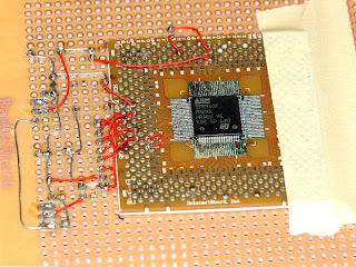
  The chip we used 5 years ago had only 80 pins & never worked.

For programming an ARM, you're better off installing stmstudio in a Windows virtual machine & buying an stlink adaptor.  It would work just as well with our home made board.  Not sure why we're obsessed with doing it in Linux.
We must have memories of a younger age, when corporate bankruptcies caused us to lose many files.  We had a lot produced in GEOS, Speedscript, Microsoft Works, a cheap publishing program for DOS (Publish-it?), & none of it stayed readable.
The best way to program an ARM without buying a programmer is  Openocd


jtag08.jpg


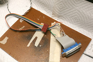
After banging on openocd for 2 days, trying to get it to work with the home made USB bit banger, we soldered a quick parport adaptor & it worked immediately.


The parport was faster than our USB bit banger & it worked.  Really wished the USB bit banger worked, since nothing on the bench still has a parallel port.

jtag09.jpg


2 more days of hacking yielded a functioning USB JTAG interface.  The trick was level conversion using 120ohm resistors instead of 1k.  Also, the SDO pin needed a BJT level conversion.


Building Openocd was a matter of

configure --enable-dummy --enable-parport

then copying src/jtag/drivers/parport.c to src/jtag/drivers/marcy2.c

Edit marcy2.c to use the USB bit banger, then add marcy2.o under every parport.o in the Makefile.  Compile it with errors, then link it manually.

gcc -o openocd main.o ./.libs/libopenocd.a ../jimtcl/libjim.a -ldl /amazon/root/vicacopter/libusb-1.0.0/libusb/.libs/libusb-1.0.a  -lpthread -lrt


Run it with

openocd -f script

where script is a file in the current directory.  So far, our script has:

interface marcy2
#interface parport
#parport_cable marcy2
#parport_port 0


adapter_khz 30
jtag_nsrst_delay 100
jtag_ntrst_delay 100
jtag newtap marcy2 cpu -irlen 4 -expected-id 0x4ba00477
jtag newtap marcy2 bs -irlen 5 -expected-id 0x06413041


target create marcy2.cpu cortex_m3 -endian little -chain-position marcy2.cpu
marcy2.cpu configure -work-area-phys 0x20000000 -work-area-size 65536 -work-area-backup 0
flash bank marcy2.flash stm32f2x 0 0 0 0 marcy2.cpu


For us, that caused it to generate

Open On-Chip Debugger 0.5.0 (2012-03-04-19:49)
Licensed under GNU GPL v2
For bug reports, read
        http://openocd.berlios.de/doc/doxygen/bugs.html
Warn : Adapter driver 'marcy2' did not declare which transports it allows; assuming legacy JTAG-only
Info : only one transport option; autoselect 'jtag'
30 kHz
adapter_nsrst_delay: 100
jtag_ntrst_delay: 100
marcy2.cpu
Info : clock speed 30 kHz
Info : JTAG tap: marcy2.cpu tap/device found: 0x4ba00477 (mfg: 0x23b, part: 0xba00, ver: 0x4)
Info : JTAG tap: marcy2.bs tap/device found: 0x06413041 (mfg: 0x020, part: 0x6413, ver: 0x0)
Info : marcy2.cpu: hardware has 6 breakpoints, 4 watchpoints
Error: marcy2.cpu -- clearing lockup after double fault
Polling target failed, GDB will be halted. Polling again in 100ms
Polling succeeded again


For a new board, you need a script which just says

interface marcy2
adapter_khz 30
jtag_nsrst_delay 100
jtag_ntrst_delay 100


That causes it to probe for the TAPs & generate the jtag newtap commands, but it doesn't get the target running.

Warn : There are no enabled taps.  AUTO PROBING MIGHT NOT WORK!!
Warn : AUTO auto0.tap - use "jtag newtap auto0 tap -expected-id 0x4ba00477 ..."
Warn : AUTO auto1.tap - use "jtag newtap auto1 tap -expected-id 0x06413041 ..."
Warn : AUTO auto0.tap - use "... -irlen 4"
Warn : AUTO auto1.tap - use "... -irlen 5"
Warn : gdb services need one or more targets defined


Examples of openocd usage came from

http://fun-tech.se/stm32/OpenOCD/index.php

http://linuxfreak.pl/elektronika/debugging-stm32-cortex-m3-microcontroller-using-eclipse-on-slackware/

http://gpio.kaltpost.de/?page_id=485


The next great task is programming the flash.  The only way to send debugging commands after openocd is initialized is

telnet localhost 4444

Key commands:

poll
reset run

reset halt

flash write_image erase /amazon/root/vicacopter/arm/copter.bin 0x8000000

That's very slow.  The USB bit banger is limited to the extremely slow 4000Hz.

verify_image /amazon/root/vicacopter/arm/copter.bin 0x8000000


is supposed to calculate a CRC on the chip.  The standard testing procedure is

reset halt

flash write_image erase /amazon/root/vicacopter/arm/copter.bin 0x8000000
reset run


There was some diabolical cut & paste from the STM32F4-Discovery & STM324xG-EVAL source code, some diabolical compiler scripts.


For the source files, we have


/opt/arm/bin/arm-elf-gcc -c -Iarm -Istm32f4 -mlittle-endian -mthumb -mcpu=cortex-m4 -ffreestanding -nostdlib -nostdinc


For the linking, we have


/opt/arm/bin/arm-elf-gcc -o arm/copter.elf arm/main.o stm32f4/startup_ARMCM4.o stm32f4/stm32f4xx_gpio.o stm32f4/stm32f4xx_rcc.o stm32f4/system_stm32f4xx.o -mlittle-endian -mthumb -mcpu=cortex-m4 -ffreestanding -nostdlib -nostdinc -Tstm32f4/ARMCMx.ld -L/opt/arm/lib/gcc/arm-elf/4.1.1/


To convert it into an image suitable for flashing, we have


/opt/arm/bin/arm-elf-objcopy -O binary arm/copter.elf arm/copter.bin


So after 5 years, our 1st toggling GPIO via home made ARM board came to life.  Programming it over the home made bit banger is too slow.  The CPU clock isn't running at the full 168Mhz.


Read more…

Courtesy of some industry demand, we're looking to offer a fully funded PhD scholarship for someone interested in developing machine vision solutions for UAV navigation.

The 'we' in this case would be the University of Canterbury, in Christchurch, New Zealand.  Specifically, the UAV Research Group in the Dept of Mechanical Engineering.

Guess what we're looking for is someone with a Bachelors or Masters degree in engineering, computer science, or something suitably technical sounding.  Preferably someone with a strong background in computer vision, or who can otherwise convince us that they are right for the job.  And someone who is interested in being at the forefront of developing UAS technologies for real-world industrial applications.

That's probably enough to convey the general idea; if anyone wants more information, comment or something and I'll get you the details of the people you'll want to speak to...

Read more…
Developer

jDrones News: Upgraded jD-MiniOSD

3689447267?profile=original

jDrones News: New jD-MiniOSD with switching power regulator

(picture from test batch, production boards will be black)

We are proud to precent first set of electronics, jD-MiniOSD v1.0

Heating issues By Gone..., we made upgraded version available of OSD that has full support for MAVLink and ArduPilot electronics. This board can handle input voltages up to 42 volts so you can easily hook up your 2S - 6S LiPos without making overheating it. This switching regulator version of the OSD was originally developed by Sam Kelly from 3DRobotics


Boards are fully compatible with original MinimOSD.

OSD firmware written by Sandro and Jani.

ArduCAM OSD Config writen by Michael Oborne.

Original PCB design by 3DRobotics

Technical details:

 - Atmel 328 MCU

 - MAX7456 Video chip

 - 600 mAh Switching power supply

 - Input voltage 5v (from FTDI) and/or 6 - 42 volts (external)

 - Size: 17.8mm x 44mm

And what is the best, we made it more efficient and price is only 49.95 USD

Deliveries will start mid March. You can Pre-Order yours from jDrones store.

Read more…
T3

3689447039?profile=original

Team,

Presently I am doing work on multicopter modeling and control. One topic of interest to me is how can the tilt dynamic model of a multicopter be accurately determined from flight data, without disabling the controls or injecting any sort of intrusive signals. It turns out it can be done from normal flight data using a few basic concepts from signal processing. The method is described here. The above plot is the measured pitch dynamic impulse response of my draganflier. The x axis is time. The y axis is the pitch rate impulse response to an impulse command sent to the ESC. There are two curves in the plot. h(t) is the response, computed from flight data. H(t) is an exponentially decaying sinusoid fitted to the measurement. In this case, the Laplace transform of the impulse response is 5/(s*s+4*s+29), which is of exactly the form you would expect to arise from an analysis of fixed pitch control. Basically, in the case of my draganflier, there is about a 0.25 second delay between the time a new tilt rate is commanded to the motors and when quad begins tilting. I have measured a similar delay for the ArduCopter. The cause of this delay is mainly the inertia of the propellers, which delays the response of propeller thrust to change in motor torque, and the inertia of the quad, which delays the tilt rate response of the quad to propeller thrust.

As a check on the accuracy of the method, it is possible to convolve H(t) with control inputs to predict tilt rate. The following is a comparison of measured and predicted pitch rate during a flight of my draganflier.

3689447226?profile=original

Don't get too excited about the way the model seems to predict the high frequency features. If you are curious about that, read my report.

From the form of the tilt dynamic model it is possible to determine the form of an optimal feedback controller. It is not a PID controller. But that will be the subject of another report.

Best regards,

Bill

Read more…

New Low Cost AHRS Sensor Board

Daisy 7 and Fox G20

3689447148?profile=original

Daisy 7 is a module with 9DOF Digital MEMS Accelerometer, Giroscope, Magnetometer, Barometer and GPS receiver in just 4x4cm Fully compatible with the cpu board Fox G20.

The cpu board is ARM9 processor at 400mhz

link to Daisy 7

Features

  • Digital triple axis accelerometer magnetometer and gyroscope
  • Digital-output X, Y, and Z-Axis ±2g ±4g ±8g dynamically selectable full-scale acceleration
  • Digital-output X, Y, and Z-Axis angular rate sensors (gyros) on one integrated circuit with a range of 250/500/2000 °/sec
  • Digital-output X, Y, and Z-Axis ±0.88/1.33/1.9/2.5/4.0/4.7/5.6/8.1Ga dynamically selectable full-scale magnetometer
  • Fast and low noise GPS
  • Digital pressure sensor 0.03hPa (resolution 0.25m) ultra high resolution
  • Fast Mode I2C (400kHz) and serial interface
  • 16 bit data output ADCs provide simultaneous sampling of gyros and acceleration while requiring no external multiplexer
  • 10000 g high shock survivability
  • Enhanced bias and sensitivity temperature stability reduces the need for user calibration
  • RoHS and Green compliant

Applications

  • Motion activated functions
  • Free-fall detection
  • Intelligent power saving for handheld devices
  • Appliances and robotics
  • Display orientation
  • Gaming and virtual reality input devices
  • Motion Control
  • IMU inertial measurement unit & AHRS
  • GPS tracking
  • Black box
  • Motion reconstruction and analysis

the code to create an AHRS and test is located here

AHRS Fox Board

Read more…

The last journey of my EasyStar

I recently bought a GoPro (HD Hero2) for my EasyStar, but managed to crash it before I could mount the camera.
But I just had to see the HD footage from the sky's, so I glued the EasyStar together again.


I throw it in the air and immediately felt it was tail heavy and banked to the left.
I trimmed it a bit and managed to fly it reasonably well, I still never got comfortable whit it.

I still got some great footage from the flight for you to enjoy.


Sadly this EasyStar never got to fly properly with the ArduPilot Mega it was intended for.
I actually think the crash was caused by the wing/wings getting loose.

Luckily the tree branches and foam probably saved my GoPro. 

I don't think I will fix this EasyStar anymore, it is quit bent and like you can see from the video the top got cut clean off. I have ordered an TekSumo from HobbyKing and looking forward to learn to fly a wing, don't know yet if APM can handle the TekSumo?

Read more…