All Posts (14048)

Sort by

PL2Q Hugin, 3D printable quadcopter

3689448387?profile=original

I have released the second version of my 3D printable quadcopter the PL2Q Hugin, the first one was the PL1Q Vampire. There is a lot of improvements on this new version, also more focused at FPV and areal video.. 

You can download it from here:

http://www.thingiverse.com/thing:19161

Here is the presentation video:

https://www.youtube.com/watch?v=MtMYRgkvqsk

Read more…

Hi Everybody!

we're members of the Ars Electronica Futurelab  in Linz / Austria, trying to create a fantastic drone-event September 1st this year.

It's happening during the Ars Electronica Festival in Linz, with about 100.000 visitors.

We try to organize the biggest outdoor-drone-swarm ever, flying above the danube river...

Even more fun, we would love to do a diy-drone tinkerer workshop - an open lab in a huge tent at the park, where enthusiasts and newbies, experts and freestylers... would present their drones, exchanging experiences, holding lectures and panels and give hands-on-workshops to interessted visitors of all ages, and get them infected with the drone virus...

We are now starting to look for local drone-experts and aficionados - to start this endeavor.

 ... to make it a huge drone party here. 

Every help is very appreciated! Please spread the word - in order to find lot's of collabs and participants...

If you do know THE expert we have to talk with... please let us know! 

I'm quoting Chris Anderson here:

>Hi Horst,

>Nice to hear from you--this sounds very cool! We're a community site, so you should post your question, just as it is >below (but with a picture or two, please), as a blog post here for community response. I'm sure you'll get a great >response and many volunteers. 

>Best,

>Chris

Thank's Chris! I did!

And we do hope for reaction and hints... Also experiences with diy-meetings that already happened... What was good, what didn't realy work... loads of ambition is here already - and we want to see it happen!

hoping for response!

Horst Hörtner

P.S: The Video shows partly the area where it should happen (city of Linz). A goPro is hanging on a Hummingbird (Ascending Technologies) I know, that is not realy a diy-drone... but we had to start somewhere ;-)


Read more…

UAS Build, Airframe HK FPV 168

3689448457?profile=original

Well I just recieved my FPV 168 from HK.com. The only damage I was able to spot from shipping was the tip of a horizontal stab. Here are my plans for the build.

I want to have a pan and tilt camera hanging on the underside of the fuselage. I bought the pan and tilt system from ServoCity. I got 2 continues rotation servos. My second payload will be a 12 mega pixel still camera to take pictures of the ground for mapping. 

The telemetry is using a 2.4 GHz with a 1W amplifier on the ground xBee.

I have allot of planing to do to get it up and running. Still awaiting all my parts to start the build. I will keep pics coming once i get started.

3689448482?profile=original

Read more…

3689448435?profile=original

Some who have followed my blog posts will know that I have been working on my HDwing design series for a return-to-launch glider concept using ArduPilot Mega.  Everything I have revealed so far has been based on relatively conventional flying wing ideas. Till now...

This forward-swept flying wing concept was inspired by the work of Justin Ammon (EdgeRC / birdofprey) that I spotted on www.rcgroups.com  A period of spreadsheet analysis and messing about with various X-plane simulations over te Christmas/New Year break demonstrated to me that, whilst unlikely to be a walk in the park, a forward swept wing could be made to work and would yield some worthwhile advantages over a mainstream flying wing.

A bunch of CAD work and several iterations later, based on an acceptably flying X-plane model, I came up with this design and I am now committed to bringing it to reality.

3689448508?profile=original

3689448525?profile=original

3689448555?profile=original

One of the difficulties with the forward swept design, especially as a pusher, has been to establish a workable centre of gravity position.  This necessitates the use of a protruding fuselage (a deviation from the pure flying wing) but offers an advantage of placing a payload area virtually right on top of the CoG.  Thus the design can accept a wide variation in payload mass and still be (X-plane) flyable.  How this translates into real world usefulness is yet to be seen, but it bodes well.

The drag-based yaw stablity of a conventionally swept wing also no longer works with a forward swept design, so the addition of a vertical stabiliser fin is required.  Bad for stealth, I know!

3689448368?profile=original

The nose cone has been sliced off at an angle to yield a removable camera pod as well as a large access aperture for working on the interior of the airframe.  I am designing in a removeable avionics tray so that the majority of the avionics and payload can be mounted on a lightweight demountable chassis to aid bench testing, modification and repair.

3689448542?profile=original

The location of the battery at just ahead of the CoG will allow me to increase its capacity with minimal adjustment to balance.   It is also is attached to the avionics tray for ease of complete systems-level bench-testing.

Personally, one of the attractions of the forward swept wing is that, similar to a canard design, all of the wing surface is lifting to produce pitch stability.  The lift distribution isn't the most theoretically efficient, but at higher speeds and lower C_L, this is not such a huge penalty.  The X-plane simulation shows a best L/D of about 19:1, which is not so bad for such a stumpy, low aspect ratio craft.  My earlier HDwing designs didn't get this far and they had the advantage of winglets and a lift distribution closer to the theoretical optimum.

The forward swept wing layout does come with some compromises but also offers compensatory advantages to exploit.  There is a whole host of detail design work to be done, but hopefully a worthwhile UAV airframe will result.  Time will tell.


Read more…

3689448305?profile=original

Greetings fellow modelers,

I thought I might share some of my experiences with a home built quad frame (X) and an APM2 brain.

Early in December 2011 I was shopping at Cool Components thinking of goodies for xmas and was attracted to the purple brushless 1000kV motors and the text “ideal as an 'outrunner' motor on a Quad copter.” I purchased 4 with the recommended speed controllers and set off on a path of discovery that lead here and to the fine work and shared experiences that is DIY Drones.

3689448140?profile=original

I had an idea to build an alloy rebated crossbar as a starting point and not too challenging to construct. I got some 10mm square section anodised alloy tube with 1mm wall thickness at the local hardware DIY store.

Before cutting it up and drilling holes I had the notion to consider the props, the popular 10 x 4.5 were recommended for the outrunners, apparently each being capable of exerting in excess of a kilogram thrust.

Not being certain of any final weight or dimensions and how these might affect performance, I erred toward smallest and as far as possible symmetrical in shape and weight. The frame dimensions are derived from the optimum prop size for the motor at 3S and a gap of around an inch between neighbors. This coincidentally provides an unobstructing central space about the size of a CDROM. All in all the design was a stab in the dark but it felt intuitive.

I cut the square tube and made two lengths at 445mm and rebated each 10x5mm at the centre point, some of the photos show how it went together using stainless fixings. A 1mm aluminium plate 110mm square provides reinforcement and a place to anchor the ESC’s and CDROM deck. 3689448290?profile=original

The motors were mounted at 275mm centres which measures up at 389mm across the diagonals.

If I build another, the diagonal distance would increase to 400 to allow the lid of a blank CDROM case to be used as a rain proof cover. ;)

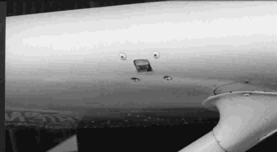
To mount the hardware APM and receiver I glued a couple of old CDROMS together with 5 minute epoxy and very carefully drilled holes that line up the APM2 and four more to match holes I’d made in the plate.

Mounting the APM2.

3689448332?profile=original

My local tool shop sells a really nice selection of round thin wall alloy tube. I used some with an inside dia of 3mm. Cutting the tube is easy if it is rolled back and forth on the bench with the edge of a sharp craft knife, paring off lengths as required. I cut a number of these as spacers and used longer stainless screws. The receiver is traditionally mounted using double sided servo tape as are the 20A ESC’s.

I dislike miles of spare cable hanging about, so I set about making up custom fly leads. Shorter ESC, PWM, motor, power and receiver to APM2 leads.

The Servo leads are taken up through the CDROM hole. The ESC power leads are taken through two 8mm holes in the aluminium plate and joined underneath in a pair of Y harnesses, the idea being to fly as little copper as possible.

Thinking about the mounting for the APM2 and I’m not sure if it even matters, but I decided to try and get the gyro chip bang on top of the centre of the quad in the X configuration, not easy when the mounting plate is a CDROM with no hard centre to work from. Although the mass of the APM2 is no longer dead centre the compromise is negligible particularly as eventual battery position makes a significantly bigger difference to c of g given the relative size and weight.

I don’t have a photo to show the legs and battery sling I’ve added, rather hastily I might add, in an effort to get airborne quickly. Some 100mm bent lengths of aluminum strip attached under the frame from the motor mounts. The design of the legs leaves a lot to be desired but worked quick and dirty as you would expect. The problem is the 1Kg mass moving laterally to the ground, if you catch a leg on the turf it’s immediately bent :) I really need to make them more skid like.

The stuff I used

Alloy square tube and various alloy strip – (Wickes)

Alloy plate – (surplus)

Alloy tube round – (Richardsons Ironmongers)

Various stainless 3mm hex screws washers and nylock nuts (Apex Fasteners)

2 x old CDROMS preferably something you want to take flight. (not a greatest hits!)

4 x 1000kV DYS Brushless outrunners  (Cool Components)

4 x 20A DYS ESC (Cool Components)

1 x APM2 – (DIY Drones Store)

2 x Turnigy 2200mAh 20 – 30C 3S1P lipo (ebay)

Both batteries are carried together in flight, but so far I haven’t made a harness to parallel wire them. Balancing when doing this for the first time is tedious and very much a manual process with safety concerns. Importantly both batteries can be positioned either side of centre maintaining a central c of g  (as near as I can tell).

I use a JR x3810 transmitter upgraded with a Corona-rc  2.4Ghz  + receiver.

I also managed to get 6 flight modes working on this radio using the 2 position p-mix switch and 3 position flap / land switch, but had to use 4 programmable mixers with offsets and the AUX3 pot to get there. I managed it using one channel.  If you have a JR X3810 or a JR XP8103 here’s one way of doing it.

Configuring the JR3810 is relatively simple providing you have the manual and understand the quirks when setting offsets in the mixers. The trick is to have the switch you are configuring in the on position and then rotate the AUX3 pot to get the desired offset.

Return the AUX3 pot to centre or just to one side to get the best 6 position distribution in the APM2 mode config.

Use programmable mixers 3,4,5 & 6. Each mixer should be set for AUX3->AUX3 mixing, effectively a rate and offset mixed with the pot for each switch’s on position in the mixer. AUX3 is one of the variable pots on the transmitter and is output at chan8 on the receiver. Use this pot to set the midpoint when no switch is in an on position. One upside to this set up is if the pot accidentally gets disturbed only the mid position on the flight switch is affected meaning the middle two modes might not line up with the mode you expect.3689448406?profile=original The rest are unaffected.

Programmable mixer 3: Rate +100, SW: ELE>F, Offset -170

Programmable mixer 4: Rate  -98, SW: LAND, Offset +98

Programmable mixer 5: Rate -34, SW: MIX, Offset +54

Programmable mixer 6: Rate +27, SW:MIX, Offset -170

Quad Performance.

The all up flying weight is exactly 1Kg according to the baking scales. That gives me approx 3Kg of thrust to launch it skyward with ;)

It works happily using the default PID settings with the current version 'AC2.4' delivered from AMP, so far I have flown 6+ flights successfully. Mainly in stabilize as the back garden is suddenly very small. The handling is responsive stable and inspires confidence in one’s ability to sling it about a bit. Indeed slinging it from side to side aggressively is so satisfying and skyward launches straight up are a favorite, so long as you first assess wind-age above fence level. I need to get out a bit more. :)

I have the channel 6 FLAP pot dialed to accept a variable P rate and have notched it up slightly in my most recent test albeit only about 10% with no ill effects and a subtly more responsive attack.

There is one negative characteristic which I need to iron out. When throttling up for liftoff, bringing the revs up slowly brings the forward facing corners off first and the resulting ground effect wants to tip the quad over. Alternatively If I stab the throttle upward the quad launch is stable and comes up with authority. At this point I am holding a very slight forward stick in to maintain attitude and consequent drift. This is hampering stabilize + simple testing where the changing yaw angle moves the direction needing the correction. I hope this can be trimmed out either by a better job of aligning, balancing and leveling or by dancing with fairies.

For the future I plan some wireless telemetry, proper autonomous flight and some FPV while it’s at it. I’d also like to build a hex or octo format for a bit more payload and redundancy.

No doubt I’ll be adding some updates as things progress.


Read more…
Moderator

Interesting drone article, featuring Jordi!

20120314-162946-pic-432918474_s160x120.jpg?9ceaf62d62f03469f648092d3990d7aeced52f2c.... While waiting for his green card, the 21-year-old was marooned in his apartment, unable to work, attend school or obtain a driver’s license.

On the other hand, he had an Internet connection. A Nintendo Wii. A radio-controlled toy helicopter his mother had given him to help kill time.

Tinkering with the Wii’s control wand and a $60 gyroscope he had purchased on eBay, he modified the helicopter to fly itself, just like the $5 million Predator unmanned aerial vehicles deployed by the U.S. military.

Five years later, Mr. Munoz is co-founder and CEO of 3D Robotics, a San Diego-based company that has 18 employees and earned more than $300,000 in revenue in December producing components for hobbyist drones.

http://www.washingtontimes.com/news/2012/mar/14/out-of-hobby-class-drones-lifting-off-for-personal/?page=all

Read more…
3D Robotics

Gesture control system for drones

From the MIT news report:

Aircraft-carrier crew use a set of standard hand gestures to guide planes on the carrier deck. But as robot planes are increasingly used for routine air missions, researchers at MIT are working on a system that would enable them to follow the same types of gestures.

The problem of interpreting hand signals has two distinct parts. The first is simply inferring the body pose of the signaler from a digital image: Are the hands up or down, the elbows in or out? The second is determining which specific gesture is depicted in a series of images. The MIT researchers are chiefly concerned with the second problem; they present their solution in the March issue of the journal ACM Transactions on Interactive Intelligent Systems. But to test their approach, they also had to address the first problem, which they did in work presented at last year’s IEEE International Conference on Automatic Face and Gesture Recognition.

Yale Song, a PhD student in MIT’s Department of Electrical Engineering and Computer Science, his advisor, computer science professor Randall Davis, and David Demirdjian, a research scientist at MIT’s Computer Science and Artificial Intelligence Laboratory (CSAIL), recorded a series of videos in which several different people performed a set of 24 gestures commonly used by aircraft-carrier deck personnel. In order to test their gesture-identification system, they first had to determine the body pose of each subject in each frame of video. “These days you can just easily use off-the-shelf Kinect or many other drivers,” Song says, referring to the popular Microsoft Xbox device that allows players to control video games using gestures. But that wasn’t true when the MIT researchers began their project; to make things even more complicated, their algorithms had to infer not only body position but also the shapes of the subjects’ hands.

The MIT researchers’ software represented the contents of each frame of video using only a few variables: three-dimensional data about the positions of the elbows and wrists, and whether the hands were open or closed, the thumbs up or down. The database in which the researchers stored sequences of such abstract representations was the subject of last year’s paper. For the new paper, they used that database to train their gesture-classification algorithm.

The main challenge in classifying the signals, Song explains, is that the input — the sequence of body positions — is continuous: Crewmembers on the aircraft carrier’s deck are in constant motion. The algorithm that classifies their gestures, however, can’t wait until they stop moving to begin its analysis. “We cannot just give it thousands of [video] frames, because it will take forever,” Song says.

The researchers’ algorithm thus works on a series of short body-pose sequences; each is about 60 frames long, or the equivalent of roughly three seconds of video. The sequences overlap: The second sequence might start at, say, frame 10 of the first sequence, the third sequence at frame 10 of the second, and so on. The problem is that no one sequence may contain enough information to conclusively identify a gesture, and a new gesture could begin halfway through a frame.

For each frame in a sequence, the algorithm calculates the probability that it belongs to each of the 24 gestures. Then it calculates a weighted average of the probabilities for the whole sequence. Gesture identification is based on the weighted averages of several successive sequences, which improves accuracy, since the averages preserve information about how each frame relates to those before and after it. In evaluating the collective probabilities of successive sequences, the algorithm also assumes that gestures don’t change too rapidly or too erratically. 

In tests, the researchers’ algorithm correctly identified the gestures collected in the training database with 76 percent accuracy. Obviously, that’s not a high enough percentage for an application that deck crews — and multimillion-dollar pieces of equipment — rely on for their safety. But Song believes he knows how to increase the system’s accuracy. Part of the difficulty in training the classification algorithm is that it has to consider so many possibilities for every pose it’s presented with: For every arm position there are four possible hand positions, and for every hand position there are six possible arm positions. In ongoing work, the researchers are retooling the algorithm so that it considers arm position and hand position separately, which drastically cuts down on the computational complexity of its task. As a consequence, it should learn to identify gestures from the training data much more efficiently.


(via BoingBoing)

Read more…

What a feeling... Finally

I joined this community over 2 years ago and have watch it grow both in technology and users.  I bought the first AP then the mega, GPS, XBee, etc. but either time or technology was moving too fast.  After 2 years of on and off tinkering, I've finally completed a project and guess what, it works as advertised!


Thanks to all of the super smart people in this community that have supported us less fortunate types that just want to fly something and for making it possible to do so.  Here is a video from today's first successful flight.


Read more…
Moderator

A new white paper at sUAS News by Leonard Ligon and Tim Adelman, Attorney at Law might be of interest to all here.

http://www.suasnews.com/2012/03/13397/the-law-and-operating-unmanned-aircraft-in-the-u-s-national-airspace-system/

This article addresses aviation law as applied to Unmanned Aircraft (UA) operating within the United States (US) National Airspace System (NAS). It further presents a review of the Federal Aviation Administration’s (FAA) authority to regulate UA flight operations by a government user (tribal, local, State or Federal). In addition, it touches on the liability of conducting UA flight operations in the NAS.


The FAA obtains its authority to regulate the NAS through statutes enacted by Congress. Therefore, any analysis of the FAA’s authority should begin with a review of the United States Code (USC). Based on statutory authority, the FAA’s responsibility is to implement regulations which carry out Congress’s intent.
Title 49 of the USC relates to Transportation. Subtitle VII relates to “Aviation Programs” and Part A of Subtitle VII relates to “Commerce and Safety.” It is in this section wherein the FAA obtains its authority to regulate the NAS.
49 USC §40103(b) states that “The Administrator shall prescribe air traffic regulations regarding the flight of aircraft for:
(A) Navigating, protecting, and identifying aircraft;
(B) Protecting individuals and property on the ground;
(C) Using the navigable airspace efficiently; and
(D) Preventing collision between aircraft, between aircraft and land or water vehicles, and between aircraft and airborne objects.”

Read more…

Foamaroo Spin Tests

We're continuing to fly the Foamaroo and are constantly amazed by what it will do.  I wanted to try using a flat spin as a failsafe/abort system for the plane and actually tested by spinning it until it impacted the ground.  My suspicions were correct - I was able to pick up and relaunch the plane after every flat spin and impact.  Only damage was a slightly loose wingtip at the end of the day.

This method of recovery in the event of loss of control will not only protect the plane and its systems but would also protect anyone/thing on the ground in the unlikely event that it came down in a populated area.

Jimmy

https://www.youtube.com/watch?v=MRo-pf0KGfY

Read more…

Variable Pitch Tricopter Using APM

I have been building a variable pitch tricopter and wanted to share my results so far.

Basically - I chose a tri and not a quad, because the tri geometry is the same as a traditional heli 120 deg swash plate. Since I can't write a firmware on my own, I wanted to use an off the self solution.

I used a home made simple frame

3 e-flite park 370 hollow shaft motors with their variable pitch props

3 castle ESCs that I had laying around.


Here is a video of the tri on a table

https://www.youtube.com/watch?v=XI_8KCJyjcA


Here is a list of my various attempts

  1. radio programed as 120 deg swash and used airplane stabilizer - worked but not great
  2. used a commercial heli flybarless system - it flew , but could not set gains low enough
  3. used my ardupilot mega - with traditional heli firmware - worked, but could not remove oscillations
  4. I retried the APM with heli firmware and reduced the swash upper and lower limits to 1400 to 1550 and lowered rate p to 0.8 and stabilize p to 3.5 no I term and stabilize D of 0,07

 This allowed me to fly and hover, but very touchy

Check out the video above - and now I need suggestions .

I think one point is I need to redesign the pitch servo so that I use more of the servo throw, but mechanically reduce the movement - I have lost a lot of resolution using such a narrow pitch range in mission planner

suggestions welcome

Al

Read more…

stallsw.jpg

One of the features of extreme high altitude flight is the high true airspeeds that are needed to generate the dynamic pressure required for airborne flight.  To minimise these extreme speeds for my high altitude glider project, I wanted to increase the flyable operation envelope closer to the airframe's stall speed, helping the reign-in the stratospheric true airspeeds!

As I was playing about tuning the roll and pitch control PID loops using my airframe model in an X-plane HIL simulation, I discovered that a relatively large amount of derivative could yield some dramatic improvements to roll control when on the edge of the stall condition.  The D term could be wound up at least an order of magnitude higher than could be tolerated at higher speeds.

To make use of this feature, I forensic'd my way through the codebase and the APM libraries to add a non-linearity to the PID speed scalar as it is applied to the derivative term.  I did this by tweaking the PID.css file in the PID Arduino library folder (not the AP_PID, as it took me a while to discover..!)  The mods are:

PID::get_pid(int32_t error, uint16_t dt, float scalar)
{
 float output  = 0;
  float delta_time = (float)dt / 1000.0;
 float deriv_scalar = (scalar - 0.5);

 // Compute proportional component
 output += error * _kp;

 // Compute derivative component if time has elapsed
 if ((fabs(_kd) > 0) && (dt > 0)) {
  float derivative = (error - _last_error) / delta_time;

  // discrete low pass filter, cuts out the
  // high frequency noise that can drive the controller crazy
  float RC = 1/(2*M_PI*_fCut);
  derivative = _last_derivative +
          (delta_time / (RC + delta_time)) * (derivative - _last_derivative);

  // update state
  _last_error   = error;
  _last_derivative    = derivative;

  // add in derivative component
  deriv_scalar *= deriv_scalar;
  deriv_scalar = max(0,deriv_scalar);
  output     += _kd * derivative * deriv_scalar;
 }

 // scale the P and D components
 output *= scalar;

(Oh, and I corrected the spelling of scalar too!)

I have also expanded the clipping of the speed scalar delivered to the PID controller from the normal 0.5-2.0 in the standard APM codebase, to 0.01-5.0  I also chose to tune the controller with the reference speed to be the stall speed of the aircraft (7m/s) instead of the default cruise speed (25m/s).

The funny (scalar-0.5) term I have used to increase the decay of the term away from the stall speed without getting into complicated and CPU intensive maths.  This allows a higher derivative gain to be used without unduly influencing normal flight. 

So, having got this compiled and working in APM and X-plane, here are the results:

When I glide towards the stall speed in stabilise mode, holding as best I can, a level flight path, but with the roll control derivative term zeroed, which is more or less how I have tuned the controller till now, the airframe slows to approximately 16-17kts before a divergent roll instability develops.  This instability can develop at slightly higher speeds too, but the main characteristic is once it develops, it is properly divergent.  There is no saving it, except for a rapid pitch down and acceleration.

3689448046?profile=original

With the non-linear D term applied, I can now achieve relatively reliable roll control very close to the stall speed.  The divergent instability is still there, but it is at a higher frequency and a much lower speed, clearing the way for operation much closer to the stall break than was possible before.

3689448059?profile=original

This work was done in X-plane 9, using an airframe model of my own forward-swept flying wing concept.  The APM code was modified from Arduplane 2.28, using Michael Oborne's AP Mission Planner 1.1.42


Read more…
Moderator

3689447845?profile=original

My original blog post offering a bounty on software for the ArduIMU v3 to make it into a very good standalone camera gimbal stabilizer attracted alot of criticism and at the same time alot more support.  There are many people who have joined my cause, and pledged to either match my bounty or contribute towards the bounty.  So many pledges that it has become hard to track.  One member suggested using Kickstarter. However as a non-US resident I was not able to create a project on Kickstarter so one has been created on IndieGoGo.

http://www.indiegogo.com/ArduIMU-Camera-Gimbal-Stabilizer?a=489994

Don't forget that whilst the $10 contribution is appreciated, and you contribute as much as you like, matching my $100 bounty is even more appreciated.  And for $225 I'll get a ArduIMU and solder the connectors and flash the firmware for you.

[EDIT: The 30 March deadline has now been extended until 11 May or until the bounty is claimed, which ever comes first.

It looks like this is getting pretty big with a number of contenders and backers, ie. more than just my $100 reward.  Whilst my offer for a $100 reward plus bonus still stands for the FIRST person to deliver code that meets the specification;  I would like to propose that the contributions/backers/funders on IndieGoGo vote at the end of the project (11 May) who should receive the funds raise on IndieGoGo (less the 9% fee that IndieGoGo charge).

So essentially there will be the $100 plus bonuses from me for the FIRST app, and the IndieGoGo pool for the BEST app.

]

Read more…
100KM

First aerial photography

3689447971?profile=original

I'm experimenting with a downward-facing point and shoot camera for aerial photography & mapping.


I had a (very turbulent) flight with APM and called an early abort because of high wind. After looking at the footage, it seemed not bad, so I ran it through hypr3d:

http://www.hypr3d.com/models/4f5e4436219bac000100003f

Some awesome software they have there. My stitching effort using Microsoft ICE was also quite succesful:

Thumbnail:

3689447829?profile=originalFull Size: (Warning huge) http://cde03.cde.co.za/share/set1.jpg

Very encouraging. I just need to get the exposure improved and fly when there's less wind.

Read more…