The competition to hack the Neato Robotics vacuum cleaner Lidar sensor appears to have been sucessful. RobotoBox, which offered a bounty, says it thinks we have a winner!
All Posts (14048)
Sort by
The competition to hack the Neato Robotics vacuum cleaner Lidar sensor appears to have been sucessful. RobotoBox, which offered a bounty, says it thinks we have a winner!
The AMA is claiming that the FAA has "forced" them to become the "manager" of recreational aviation that will force every recreational sUAV user to be a member of the AMA or not be able to fly.
From one of the AMA's "ARC" FAQs:
"AMA would prefer to see a single set of guidelines managed by a community-based organization
that establishes the standards for all of model aviation. AMA is actively developing a
comprehensive set of model aviation guidelines from its current safety standards for submittal to
the FAA and hopefully acceptance and approval before the sUAS SFAR becomes a reality in
2011.
This may sound to some like the Academy is trying to force all modelers to join the AMA.
Certainly AMA believes there is strength in numbers and the health and welfare of the hobby
undoubtedly depends upon the presence of a strong national organization that can speak for and
advocate the interests of the aeromodeling community. But, forcing modelers to join the AMA is
by no means the intent of the Academy’s approach to the sUAS rulemaking. AMA’s sole aim is
to work through this issue that has been somewhat forced upon us, and achieve an end result that
allows the modelers to continue to enjoy the hobby in much the same way as they have in the
past"
Seems like a sneaky way to bolster their falling membership by millions. The AMA has no oversight policy for its members or clubs and its safety policies are based soley on what an insurance company will allow. Let us hope that the AMA will be ignored by the FAA. A set of atandards for everyone to follow instead of forcing everyone to get an AMA insurance policy is what is needed.
Anyway, I ordered myself an Arduino board and set about going through the learning examples, having mixed success with my progress (more with software, less with hardware - I am truly useless with electronics after failing to learn even the most basic parts of it at school) until I finally decided to bite the bullet and buy the ArduPilotMega board and the oilpan from the UK's only stockist (or so it seems) http://www.coolcomponents.co.uk. A bit of soldering later (even I can't mess that up) and I had the basics working. I even managed to get my Mac to upload the code and talk to the system via the CLI. A few weeks (and another pay day later) and I had a complete MediaTek GPS system in my hands from across the pond. Another bit of soldering and my initial payload package was pretty much complete.
Then, a bit of luck! One of the new starters at work is into FPV and offered to donate one of his old airframes to my cause. Yes, it's battered. Yes, the nose is held on with black tape and the wings have clear tape reinforcing the [slightly broken] main spar. It might also have resin holding the tail section on, but it is still an airframe and it comes with servos and an ESC.
So, what next?
Well, I have another heli flyer from work lending me an old six channel analog radio system when he can find it, and I need to source LiPos and a prop, but the most important thing I need to do is to try and fit the bits of the APM into the airframe. My current thinking is that it might involve a little bit of cutting, some hollowing out, and maybe the creating and attaching of a new nose section lovingly made from new foam. I'm also going to be spending a lot more time with the APM code, learning how to code it, and seeing if there is anything I can do to make it better. Already I have some ideas for a new airfame and some extra features, but that would take a lot more experience of coding than I have now to put together. I have time though, and I am learning. I just need to _not_ kill the APM chip, like I did the other day with the one on my Arduino dev board.
I'm hoping that this blog will serve as a memory to how I get on with the build, the initial testing and the more advanced things that I hope I will end up doing with the project. With any luck I'll be able to update it regularly with more successes than failures.
Martin reports: "Last weekend (27./28.11.2010) someone broke into the University of Bergen, Norway and stole three Paparazzi-equipped autonomous aircrafts/systems for atmospheric research based on the Multiplex Funjet. The break-in was very precisely targeted to only the systems that had been used in many measurement campaigns. Any information about the disposition of this equipment (e.g. suspicious offer for sale) is highly appreciated.
More detailed descriptions at the site of the Norwegian RC club:
http://forum.radiostyrt.no/vb/conten...A5let-fra-UiB?"
http://forum.radiostyrt.no/vb/conten...A5let-fra-UiB?"
Video from one of the UAVs on an arctic mission:

power supply and esc

first test frame

test set up


motor with 2 layers of rubber fore damping.
https://www.youtube.com/watch?v=DjRsPxao5Xk
test


lot`s of work to be dan.

i made an plexiglas top plate so i can see the led`s.

camera mount.

frst test fit
Just wanted to share my excitement about the arrival of my Arducopter.
Want to thank and congratulate with Jani for the super fast shipping (despite one month of wait in the pre-order list): the box left the office last Friday and this morning, Monday, 3 days later with a weekend in between, it arrived at my place, in Bruxelles (Belgium)
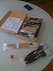
Here is the content of the box:
In main box the full arducopter kit, then 2 sets of spare propellers (you never know what you can hit, and propellers are the first thing to break), the magnetometer and a crash kit (one complete arm).
As a side note, I was not able to close the box after I took the additional items out: the guys that packed it must have insane packaging skills for having assembled this 3D puzzle :)
Here some additional pictures:

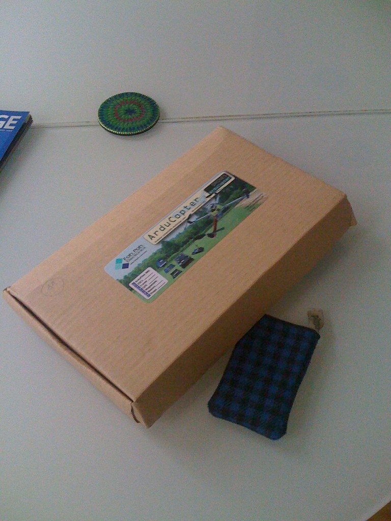
Impressed by the size of the box: I expected it to be bigger, while it is pretty small. Look at the iPhone cover I used as reference. Positively impressed: less problems for storing it away :)
I don't think people will be interested in me posting my building log here in the main page of DIYDrones, so I think I will do it on Flickr: Arducopter Building Log.
If you are interested you can also subscribe to the RSS feed: http://feeds.feedburner.com/ArducopterBuildingLog
Let me know your thought on this.
Hope to be able to start working on it soon :)
I've updated the APM Beta code (zip file version) to roll up our latest bug fixes and tweaks. The most noticeable one is that we've moved back to the excellent circle algorithm that we had in ArduPilot2.7 (we were experimenting with a different approach with APM, but the ArduPilot one turned out to work better in the real world). You can see some results from one of my flights yesterday above (using a SuperStar--moderate wind).
Overall it's flying very well and has been tested on a large and growing number of aircraft. It almost invariably works right out of the box with the default gains. All you should need to do is change the DIP switches to get your servo directions right and use elevon mixing if that what you need.
This is the last beta update. We expect to release the 1.0 code (not beta) this time next week. As always, you can follow the progress here. As you can see from that activity tracker, the APM Dev Team has been busy.
Hi, I'm wondering if there's a way to obtain AoA and sideslip angle information from GPS speed data? There is vertical speed and 3d speed so this would probably be able to give me an estimate of the angle of attack, but for sideslip, I would have to have the y-component of the speed. Is there a way to get this from GPS or the IMU unit?
I have also tried it for one whole day but am at a loss of how to get the information to be passed from ArduIMU V2+ to ArduPilot so that I can use XBee to transmit it wirelessly to my GCS. Any clues from any good samaritans out there?
Otherwise, I think I am left with integrating acceleration information from the IMU which will probably be susceptible to a lot of errors, and also since it depends on the 'initial conditions' the errors will accumulate continuously.. :( Any ideas on whether this is a feasible option at all?
It's getting cold and I'm limited by space to fly and money to repair crashes, so I'm going to feed all my toy-wants by starting off with an AGV, and using the knowledge and experience to make liftoff next spring smoother than would otherwise be.
I already tried using a Traxxas Rustler, but keeping control at low speeds and preventing motor overheats was an issue, so...browse....browse...browse....ah-ha!
What better vehicle to accidently go off-roading with at low speeds than a rock-crawler?! :-)
Kit form - No electronics - $150
Basic crawler ESC and Motor installed: $130-ish
What I had on hand: Arduino Nano V3 and breakout board
Purpose: Main Processing
Servo Control
IR Distance measurement using a Sharp GP2D15 on a pan/tilt
What I bought: ArduIMU+ V2 Flat, and HMC5843 - Triple Axis Magnetometer
Purpose: Rollover warning, impact sensing, heading input, turn-rate input, future GPS
The CreepyAGV V1.0
Here's what I'm flying with ArduPilotMega:
--EasyStar (default settings work fine)
--SuperStar EP (default settings work fine):
--Skyfun (default settings work fine)
--Skywalker (picture at top)
--And of course ArduCopter!
What airframes have you flown APM with? Any tips or changes needed?
I've been building both AutoPilots, and QuadraCopters, and I wanted to drive more servos and ESCs, with less jitter, so I used some ideas from the Paparazzi gang and developed a way to drive up to 10 servos with just 2 output pins from an Arduino or ATMega8.
The design uses just one chip, a Johnson style Decade Counter, and requires only two output pins from the Arduino. The Arduino uses one PWM pin (pin9), and one general IO pin (pin8). All the pulse are generated in sequence on the PWM pin, then spread out to the individual servos via the decade counter. The decade counter costs 63 cents.
Now I can build Hexa-Copters without having to use I2C ESCs, and still have servo outputs available for camera controls.
This should have come out yesterday but admissions essays got in the way. Anyway, I updated the GCS, and now it supports waypoint-ing by clicking on the map. You can also insert waypoints in between existing ones by using the Add Before/Add After buttons. Delete waypoints by using the shiny red button.
To set up options for takeoff and landing, click "Takeoff / Landing Options". You'll be shown a screen like this:
... where you'll be able to set the takeoff pitch and altitude, as well as add CMD_LAND_OPTIONS entries. Fill in the boxes and click Add Landing Option, and it'll be automatically added to the list. The list is held in sorted order. To delete an option, select it and hit the 'Delete' or 'Backspace' keys on your keyboard.
Finally, You can export your mission to a waypoint writer file. I've only exported to the mission[][5] array, so you'll need to create the file and then copy and paste it in.
If you're using the GPS Simulator with this, and suddenly see the CDI (lowest instrument on the left) needles suddenly jerk around, just ignore it for now. I'll add in functionality so that the CDI will show your deviation from the plotted mission soon.
The updated .AIR file can be found here: http://zhiquanyeo.com/apm-gcs/APM_GCS_ControlStation.air
Have fun and as usual, let me know if there are any bugs, or comments :)
More cool stuff with Willow Garage's Robot Operating System (ROS) from I Love Robotics: "Updates to Brown University's ROS Software Repository should soon include the ardrone_brown driver which improve the AR.Drone's ROS performance with access to the front camera. The video above shows the system in action tracking an AR Marker."
My new Kopter!

JYNX 4.0: This is JYNX glider designed by RCPLANS.nl . Now a days I am working on it and modifying it for electric motor powered. I am attaching whole plans of this glider. Totally made of depron foam and low cost plattform for APM.
The JYNX is a depron flying wing glider, designed for sloping. It's a simple build, which took me a week to finish in the evening hours. The JYNX has a 15% symmetrical airfoil, which is created by folding the wing from the leading edge around a depron spar. there are no carbon fibre reinforcements used, yet the wing is very strong and stiff. This plane is light on the budget too, as it uses just two cheap 5 gram servo's, a 4 channel receiver and a small battery.So far the prototype has flown a few hours, in which I've experimented with the center of gravity, control throws and reflex. You can find the results on the plan. Keep in mind that reaching the indicated center of gravity will mean you have to place the receiver and battery at the back of the fuselage.The JYNX has had a good number of pretty rough landings, but I haven't found a single scratch or crack. This is a very durable plane.Finishing has been done with clear packing tape used for masking, acrylic paint applied with a brush, and a dry paintroller to absorb and spread the paint. The results can be compared with airbrushed paint.The available space in the fuselage is quite limited. I'm still working on a version with a brushless motor, and might release a new plan for a slightly bigger fuselage soon.
Click the file below to download plans


Here is a preview of my long range wireless modem.
It's based on a Radiocrafts 868Mhz module (RC1180HP) with 450mW RF output power and good receiver sensitivity.
I'm going to use this for modem telemetry and antenna tracking, one in groundstation and one in the airframe
It has the following features:
1x LCD 102x46dots
4x Buttons
1x MicroSD slot
3x analog to digital inputs
1x I2C
1x SPI (if LCD is not used)
1x RS232 (TTL)
2x Timer outputs (used to connect a 4017 to drive servos)
4.5 to 32volt DC input
Dimensions are 44mm x 55mm x 5mm
More info will be added later.....and yes it will be open-source, I will share all design info if you want....
Edit:
Here you can find the schematics: RC1180HP-Modem.pdf
I noticed this book on the bargain shelf of Barnes and Nobel and picked it up--I haven't been able to put it down since. It's a terrific romp through 150 of the worst aircraft designs in history, but what it really is a catalog of all-too-common engineering errors, such as:
- Solutions looking for problems (such as jetpacks and the Hillar hovering sniper platform)
- Engineers designing planes with no sense of what pilots wanted
- Dependencies on exotic fuels that aren't available
- The "Gillette problem" of adding more wings than the last guy, including some crazy 8-wing things
- Delivering so late that the need is gone.
It's beautifully illustrated and very funny, thanks to the sparking writing of Jim Winchester. And the stories are hilarious. Here's my favorite passage, about the ME 163 Komet, an experimental German rocket plane:
"The fuels in the Komet were highly corrosive and would dissolve organic material (such as the pilot). To avoid this, the pilots would wear special asbestos-fiber suits"
Kill you now or kill you later ;-)
Highly recommended!
Highly recommended!