All Posts (14048)

Sort by

Arduino Number

I am confused about the "Arduino " edition number between# 13 or #15 ....In the Ardupilot setup instructions it links youto the Arduino15 to download and use but no reference to13....Yet here some say we have to use 13 for certain editions of“ Ardupilot “Help requested please ....Thank you De VO1ET Jerry .....
Read more…
Moderator

JR mx 12 long range TX

My JR mx12 FM 35 Mhz TX got an overhaling made by Thomas Scherrer.FM 35 Mhz 10 mW - UHF 433 Mhz 500 mW ( secret button1,3 W)

Replacement of the FM tx to the new long range UHF tx.

OLD FM TX

New UHF TXDon't have to think about channel or "range" anymore.With a Yagi antenna and the new tracking antenna from immersion I hope to get a good range. My goel is about 15-20 km.(Did I mention the 7W booster I also ordered from Thomas Scherrer shhhhh).I'll gess the video link will be the week point now.More will come about this new option.

Read more…
3D Robotics

Day one of Maker Faire

Massive day at Maker Faire yesterday, with Jordi manning the booth in the Maker Shed and me bouncing around with kids between that and the GeekDad booth (shown above), which is my other hat here. We gave a UAV talk on the main stage at 6:00 and then did a photo shoot outside for next month's Make Magazine. Child labor was once again enlisted:

Now for Day 2. DIY Drones will be in the Maker Shed demo row and in the GeekDad booth (next to the Lego presence, of course) in the South Hall. Blimpduinos and ArduPilots on sale. (We've almost run out of BlimpDuinos, so I'm scrambling to make more this morn!)
Read more…
Developer

My UAV helicopter (which can't fly)

What can it do:the atmega 128 can control all the servos and the engine speed. It can communicate with my Windows PC via the xbee so I can send it commands (like inc/dec engine speed, tail rotor servo, etc). It know's it's pitch, roll and heading using the sparkfun 6DOF + the compass (combined using kalman filters).What can't it do?well, first off it can't fly (yet). it can't even control it's horizontal direction using the tail rotor at least not since I attached the main rotors (before it was controlling it's direction pretty well but the main rotor has changed the dynamics of everything a lot it seems). It doesn't have a GPS nor anyway to know it's elevation.Basically I think the hardware (although a bit messy) and basic software is probably far enough along to allow it to hover but I'm currently stuck on getting the control algorithms correct (i.e. when you're 20 degrees from target and your speed is 50 deg/sec and tail servo is at position mid + 80, what should it do?). I've been looking at a few people's projects (especially vicacopter) for ideas and I've tried a few things including a PID controller and even played around squeezing a neural net into the Atmega 128 (it can fit!) but so far pretty limited success.I'm interested in working with others to get a UAV helicopter working. I love the challenge of programming on these tiny CPUs so that's probably the area I can contribute the most in (especially if it's in C, C++, Java) and although I'm pretty happy with the AVR cpus I'm willing to change platforms if necessary. Learning about the hardware since I started this project about 9m ago has been a lot of fun as well as it's something I hadn't been exposed to before.All comments, suggestions for improvements, ideas more than welcome!Here's the parts that have gone into the helicopter:eco8 helicopter (click under link for IKARUS Electric Helicopter)http://www.ikarus-modellbau.de/onlineshop/deutsch/index.php?lang=1hyperion brushless motor and esc purchased from my local hobby shop:http://www.aircraft-world.com/shopexd.asp?id=6382http://www.aircraft-world.com/shopexd.asp?id=5195the CPU is an Atmega 128 with 32k external ram on a pretty basic breakout board:http://www.besttechnology.co.jp/goods/cpu/index.htm#BTC068I program the above in C using Eclipse + winavr:http://sourceforge.net/projects/avr-eclipse6DOF (3 gyros, 3d acclerometer) purchased from sparkfun:https://www.sparkfun.com/commerce/product_info.php?products_id=8454Compass also purchased from sparkfun:https://www.sparkfun.com/commerce/product_info.php?products_id=7915An Xbee module (also purchased from sparkfun) for communicating with my windows PChttps://www.sparkfun.com/commerce/product_info.php?products_id=8695rpm meter built from some more parts from Sparkfun:https://www.sparkfun.com/commerce/product_info.php?products_id=8642https://www.sparkfun.com/commerce/product_info.php?products_id=8644
Read more…
3D Robotics
Your Blimpduino kit comes with most of what you need to compete the blimp, and all the hard-to-find and unique parts. Here's what else you'll need:

  • A soldering iron and solder
  • A FTDI cable (DIY Drones cable recommended) to program the board.
  • Helium (Available in the balloon kits available for $18 at Target, or a larger tank from Amazon)
  • A 7.4v LiPo battery (any other one of that approximate size and capacity will do, as long as it's under about 35-40 grams)
  • A balancing charger (This one, with this power supply, will do the trick and is inexpensvie)
  • If you want to use RC mode, you'll need an RC system with at least three channels. Any will work, starting with simple systems such as this one. You''ll also need two female-to-female RC cables.
  • A 9v battery for the ground beacon
  • Double-stick tape to attach the board to the gondola
  • Velcro tape to attach the gondola to the envelope
  • Superglue
Read more…
3D Robotics

Loading the Blimpduino code

Here's how to load the Arduino code on Blimduino:

First, you need to download and install the latest Arduino IDE.

Then, download the latest Blimpduino code from the code repository.

Unzip the file. You should have a directory that looks like this:


Now plug in your FTDI cable into the six-pin FTDI port on the Blimpduino board. Make sure the BCK and GRN labels on the board correspond to the matching black and green labels or wires on your FTDI cable.

If you're using the Sparkfun FTDI board (it requires a USB cable, if you don't already have one), it will look like this:


If you're using the DIY Drones FTDI cable, it will look like this:


To load this code, power on the Blimpduino board with the battery or using some other 5v power source (do not attempt to just power the board with the FTDI cable. We did not connect the power pins on the FTDI port to the processor to avoid power conflict when the board is powered by the Rx and you're using the FTDI as a serial monitor). The red power LED should go on.

Then in the Arduino software in the "Tools" menu make sure you've selected the right serial port (the FTDI cable will create a new one, which is probably port 5 or higher). Also ensure that the board selected is "Arduino Pro or Pro Mini (8 Mhz)"

Load the BlimpDuino "sketchfile", blimpduino[version].pde, which will load the rest of files in tabs.

Your interface should look like this:


Now press the "Upload to I/O board" icon (the little arrow pointing to the right). If you have the Sparkfun board, after about 20 seconds you should see a red LED flash a few times and then stay on for a while as the code is being uploaded. On the DIY Drones cable, which doesn't have a LED, just wait. After about 30 seconds the software should report that the sketch was successfully uploaded by reporting "Done uploading" and reporting the Sketch size. If not, check out the Arduino debugging tips here.

Note: the Arduino IDE has a handy built-in serial monitor, which is a great way to watch Blimpduino work. The code reports a lot of status messages over serial, which you can see while your FTDI cable is plugged in. Just click on the little box icon on the far right and ensure that the baud rate is set for 38400, as shown:


Read more…
T3

UAV DevBoard is back in stock

UAV_v28.JPG

The UAV Devboard is back in stock at SparkFun, with a new design.The reason for the design change is that Analog Devices no longer makes the gyro that we were using on the previous board, so we have switched the design to the LISY300AL. Paul Bizard and I have thoroughly tested the new board on fixed-wing aircraft, the LISY300ALs work just great with DCM.We have modified all of our existing firmware to be able to run on either board, and will make sure that all future firmware will also work on either board. If you have written firmware for the UAV dev board, you will only have to make a few minor changes to run it on the new one. The two board designs are nearly identical. The only differences are:1. The new board uses LISY300AL gyros instead of the ADXRS401, and the 6g range instead of the 1.5g range for the accelerometers. This will allow you to provide aerobatic control without saturating the sensors.2. The gyros, the accelerometers, and the A/D reference voltage are all tied to the 3.3 volt regulated supply. This will totally eliminate drift of gyros and accelerometers due to supply voltage changes.Each firmware project now has both a "green" version for the previous board and a "red" version for the new board.
Read more…

New InvenSense IMU-on-a-chip

<a href=www.engadget.com/media/2009/05/invensensememsgyromotion6-axis.jpg"/>

gI_Invensense6axisBlockDiagram.JPG.jpg
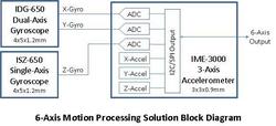
Press Release"The world's first 6-axis MEMS-based motion processing solution delivering the smallest, most robust inertial measurement unit (IMU) for CE applications. This solution includes two 4x5x1.2 mm packages for the gyroscopes and one 3x3x0.9 mm package for the accelerometer, providing a small 7x7mm equivalent footprint with 10,000 g-shock rating"Looks great! It says world's first, but i swear there was already an Analog Devices onearound , but very pricey... Anyway, I cant wait to see this in a RC plane. Good to see prices falling.I wonder if this was what was used in the IMUDot we saw earlier?
Read more…
3D Robotics

FMA no longer carrying Z sensors

I'm sorry to report that FMA is no longer carrying Z sensors. They ran out of existing stock and because their basic Co-Pilot doesn't require them, they won't be making any more. They will continue to make XY sensors, which the Co-Pilot does use, and those should be back in stock in a few days. We're currently exploring alternative sources for the Z sensors, but in the meantime, I suggest you buy them from Dean Goedde for $40 including cable (scroll to bottom for price list).[Update: Turns out that those may not be totally compatible (they're 3.3v and require special wiring to our 3.3v shield). Stay tuned....we're looking at other options.] [Update 2: Dean writes and says that they are compatible: "My Z head is 100% fine at 5V. The analog output will be 1/2Vdd for a balanced horizon view, and skew away based on tilt. After all, myself, FMA, and Paparazzi are all using the same components and design. The AD8551 OpAmp is being used in all 3 of our Z heads and is fine to at least 5 volts.]
Read more…
3D Robotics

Jordi figured out how to make the ArduPilot shield $5 cheaper--now it's just $32.50 with the differential pressure sensor. Features: --Airspeed sensor --Battery voltage sensor --3.3v power regulator to support 5Hz GPS modules --Allows programming of ArduPilot without removing GPS --Easy attachment of other sensors and wireless modems If you've got an ArduPilot, either 168 or 328, you totally need this. Flying with an airspeed sensor is 100% better!
Read more…
Developer

Wiring up uBlox! (Only for PRO's)

Hello again! I'm not so good making intros, so imagine you just read a long and well redacted introduction of why uBlox (the best GPS ever) is so difficult to find and interface with (Specially the SparkFun version). So let's go to the point. ;-)If you are beginner please don't try to make this.Fallow this pictures in order to make the wiring (hurry!):

And this is an example of how to connect it to ArduShield, but you must configure the unit first! So continue reading for instructions.

You will need to configure uBlox module using U-center, only have to do it once, the settings will remain in the EEPROM forever. Download U-center from here and install it:http://www.ublox.com/en/evaluation-kits/u-center/u-center.htmlMake sure you supply the unit with 3.3V and interface it using the FTDI cable. When you are able to see real time data with U-center, you are ready to proceed. Click here for a u-Center user guide.Now UBX has 8 Message Class, we only use "Class 0x01" called "NAV":

Each class has "Messages ID's", we only need 3 ID's of "Class 0x01", the ones marked with blue:

If you need more information about uBlox protocols please download this uBlox_Protocol_Specification.pdf.Everything else must be disabled. Now that you know what we are trying to do, lets go with a more detailed instructions:Go to Message View by pressing F9 (menu View->messages view):

(I'm using Paparazzi instructions but modified).1. Right Click on the NMEA Text on top of the tree and choose disable child messages2. Choose UBX->CFG->NAV5(Navigation 5) - set it to use Airborne 8 <4G. This tells the Kalman filter to expect significant changes in direction.Note that this setting is only good for faster moving airplanes. For a fixed position hovering heli, 'pedestrian' setting is better3. UBX->CFG->PRT - set USART1 to 57600bps4. Change the baudrate of U-Center to 57600bps if the connection is lost at this point5. UBX->CFG->RATE(Rates) - change the Measurement Period to 250ms This gives a 4 Hz position update since 4 x 250ms is one second.6. UBX->CFG->SBAS : Disable (SBAS appears to cause occasional severe altitude calcuation errors)7. UBX->NAV (not UBX->CFG->NAV): double click on POSLLH, STATUS, VELNED. They should change from grey to black.8. UBX->CFG->CFG : save current config, click "send" in the lower left corner to permanently save these settings to the receiver.You are done!! Now plug the GPS to your ArduPilot and fly like a PRO ;-)[UPDATE:]Another great way to do it:

3689318405?profile=original

3689318329?profile=original

Read more…

ArduPilot1. with EEPROM function.

It would seem I’m not the only one using ArduPilot1 code so I fiddled with the code and took some extracts fromArdupilot 2.1 and used it to save the home alt in the EEPROM.When the autopilot resets it self during flight or is reset by the user (quick 5 times toggle of AP switch) the home position (WP 0) would reset and for that given position during the flight the alt. will be “0”.If you descend the alt would read something silly like 65000 subsequently with AP armed then your plane start a immediate dive, but with home alt saved to EEPROM it still reads the correct height you are flying at and then only adjust for WP1 alt.The only problem when a reset happens is the nav routine starts from scratch with WP1 again, it doesn’t matter if you are on your way to the last waypoint or midway to WP3. My next attempt would be to write the current waypoint to the EEPROM and WP0 lat & long.To save home alt. add a jumper between pins 6 & 7 power-up and wait for a valid GPS fix on Ardupilot give it a nother couple of seconds (just to be sure) now home alt is saved to EEPROM. Maybe a led flashing at the end of EEPROM write would be a good idea?You can remove the jumper and reset the board either with the reset button or by cycling the power source.WARNING.I have not flown this code yet but it works fine on the simulator and will give it a go this coming weekend. --- hopefully!and I'm not a programming guru so the changes might not be completely "sound", maybe Jordi can give the code his blessing.ArduPilot13.zip
Read more…

Phase 1 - Define the goals of your UAV project

Goals:-I want my UAV to be able to go from point A to point B, take a picture, go back to point A and then land safely.-My UAV should be built using the cheapest commercial available products and the total cost should not exceed 1000$.-I'm giving myself no more than a year to complete this project.List of my skills:Update: 2009-05-27: Thanks to David for pointing out the excellent article of Cory about the list of skills set which are nice to have if you want to build your own UAV.Here are the skills that I think I have.ProgrammingExperience with CAble to compile softwareCan program embedded systems - NoKnow how to find the appropriate resources for support (forums, mailing lists, wikis, etc.)Radio Control AircraftBe able to take off and land with confidence - NoBe able to fly simple patterns - NoUnderstand model aircraft setup - NoBe able to make simple repairs to model aircraft - NoBe familiar with tools and techniques used for model aircraft - NoUnderstand the care and usage of lithium polymer batteries - NoBe a member of the Academy of Model Aeronautics (For access to certain flying fields) - NoElectronicFamiliar with embedded systems - NoKnow how to interface electronic components to micro controllers - NoBe able to locate, read, and understand data sheetsKnow how to troubleshoot electronic systems - NoUnderstand signal timing - NoBe able to solder small components and wiresBe able to fabricate wiring harnessBe able to read schematicsControl TheoryUnderstand PID control - NoGeneralAble to learn without guidanceStrong ability to troubleshoot systems
Read more…
Integrated picoc as a runtime thread in VicaCopter. The current version locks up, it doesn't do floating point, it crashes your entire autopilot when it encounters an internal error, but after working around all the problems, managed to get some nifty flights out of it.It's like turtle graphics with a very very expensive turtle. U can build up incredibly complex flights out of reusable maneuvers. U can repeat maneuvers. U can nest maneuvers in maneuvers.Ironically, picoc was written to fly airplanes but its author never flew it in an airplane. His only application was that Surveyor rover.The lack of floating point means we can only do relative waypoints & no latitude & longitude.

That was a 15m altitude change & 2 pirouettes in picoc.

That was the cross mission & 2 circuits in picoc.

That was 4 orbits with the nose pointing in different directions in picoc. Impossible with tables of waypoints.It locks up if you forget a comma in an argument list. Don't use "assert" in programs which are intended to fly things. Run it in a thread so if it locks up, it doesn't crash you. A floating point trig library would be nice.
Read more…
T3

PicPilot + Ardupilot Ground Station

I got the Radio Interface running today and am talking thru the XBee radio to the Ardupilot ground station. I'm not sending all the data yet, but most of it. That's my house down there!

That just leaves the SD card as the last bit of hardware to validate. I'll probably wait a bit on that and focus on getting the magnetometer integrated with the attitude estimator. Then I think I'll put it on an RC car and tool around to collect some data. I need to start thinking about what plane/helicopter to put it on first so I can start down the stabilization/navigation path.Power Supplies - workingProcessor - working12 bit AD - workingGyros - workingAccelerometers - workingAirspeed Sensor - workingUSB - workingAltitude Sensor - workingMagnetometer - workingGPS Interface - workingRF Interface - workingCurrent Monitor - workingVoltage Monitor - workingSD Card - Not DoneServo Outputs - workingPWM In - working
Read more…
T3

Pic32 Autopilot Progress.

Got the Altitude sensor working (BMP085). This graph shows the responds from holding the autopilot near the roof then lowering it to the floor, then back again. All in all about 8 ft. A little noisy, but not too bad. I haven't attempted any filtering of the data yet.

This graph shows the accelerometer data as I hand held it and did several rotations about the roll and pitch axis.

This plot shows the noise floor of the IDG500 and LISY300AL. The LISY300 is a little quieter, but not by a whole lot. For the most part I'm happy with the performance of the IDG500. Check out the video of the Attitude Estimator if you haven't already.I also got the PWM inputs done for measuring the pulses from the RC Receiver. Here is a quick rundown of status.Power Supplies - workingProcessor - working12 bit AD - workingGyros - workingAccelerometers - workingAirspeed Sensor - workingUSB - workingAltitude Sensor - workingMagnetometer - workingGPS Interface - workingRF Interface - Not DoneCurrent Monitor - workingVoltage Monitor - workingSD Card - Not DoneServo Outputs - workingPWM In - workingI'll get the RF Interface running tomorrow and start sending messages to the ArduPilot ground station. After that I need to finish up on processing the magnetometer to give a heading for removing drift in the Yaw axis of the Attitude Estimator, then it's time to start looking for an airframe to install the autopilot in and begin the stabilization process.Regards,Brian
Read more…
3D Robotics

The more we get into the RC world, the more we're shocked by how overpriced and underpowered a lot of RC equipment is. Most of the specialty electronics, from ESCs to servo amplifiers, are just cheap PIC chips with a few support components. The parts cost a few dollars, but the completed boards often sell for as much as ten times that A good example is the failsafe/multiplexer ("MUX"), which allows you to switch between two inputs for RC control (in our case, that would be RC or autopilot control). The main one on the market is the RxMUX, which costs $79 (shown below).

We thought we could do better. So Jordi created the DIY Drones Failsafe/MUX (shown at the top of the page), which uses the same Attiny45 and multiplexer as ArduPilot. Ours is $16.90, and is literally both one-fifth the size and one-fifth the price as the RxMUX. It also includes all sorts of other goodies, such as recognizing the middle position of a three-position switch and having a programmable signal-loss behavior. Plus it's open source, so you can do anything you want to the code. Our failsafe/MUX is four channels, rather than eight (everyone preferred the smaller one and thought four channels was enough) but if you want an eight channnel one like RxMUX we can make it for you easily for about the same price. Here are the two side-by-side, with a 9V battery for scale.

What else can we take 80% of the cost and size out of?
Read more…