Jack Crossfire's Posts (188)

Sort by

AR Drone 2.0 teardown


ardrone13.jpg


For all the talk of the drone revolution, there remanes but 1 vehicle which is truly a plug & play drone for the masses: the AR Drone.  In true dot com tradition, ifixit.com made zillions of dollars in venture capitol & never did a teardown of the 2.0, so it was time for the unemployed masses to step in.


ardrone01.jpg

The entire electronics assembly & battery are supported by a piece of foam.  The boards still have many wires connecting to the frame, subjected to the full vibration.

ardrone06.jpg

A common 640x480 camera does the optical flow & seems to send some kind of compressed data.  It may be a 30fps USB cam.

ardrone07.jpg

A custom AR Drone sonar circuit.


ardrone02.jpg

ardrone03.jpg

It's a mane brain board & sensor board, connected by

ardrone04.jpg

just 8 pins.  The 2 cameras connect to the mane board.  The front cam may output uncompressed data.

ardrone05.jpg

A common PIC serializes the data from all the sensors.  Maybe it also fuses the sensor data.

ardrone08.jpg

The air pressure sensor is under a piece of foam designed to not touch it.

ardrone09.jpg


Standard gyro + accelerometer chip & unknown magnetometer, not that it matters since everyone is going to use the mpu9250 tomorrow.


ardrone10.jpg

The radio

ardrone11.jpg

with a trace antenna.

ardrone12.jpg


Under the can, it's a power management & USB chip from TI, some kind of flash & RAM from Micron.  In usual modern fashion, the mane processor would be sandwiched under the big chip, so there would be no way to see it.


The 1st test ever done to see how accurately the optical flow holds its position. Over carpet, it's hopeless & seeks the nearest line. With a target, it's decent at the default altitude, but slips off at higher altitude. As soon as it slips over carpet, the altitude reading goes high & it descends. It could be improved with more software.
Read more…

Ladybird autopilot

ladybird31.jpg

The 1st flights good enough to get on video. It's extremely unstable, but there is hope. The MPU9150 was the only way to get the sensors small enough. It might also be the smallest thing currently flown by a computer, anywhere in the world.

ladybird35.jpg


ladybird33.jpg


There was some chance noisy stick voltages were making it unstable, but the oscilloscope showed the noise was down near 20mV while flying deflection was near 500mV in the pitch & 100mV in the roll. The Y position has more error because the camera can't sense depth.

NewFile11.bmp


roll & pitch sticks while flying

NewFile9.bmp


roll & pitch sticks while flying

NewFile10.bmp


 roll & pitch sticks while flying

NewFile7.bmp


inactive stick noise

NewFile8.bmp


 changing stick by 0.01

ladybird32.jpg

ladybird30.jpg


After a flimsy hot gluing of the board on top, the MPU9150 gave drastically improved results over having 1 board for a magnetometer under the battery & a 2nd board on top for a gyro.  There's still a bit of error because the board isn't perfectly flat, but it manages to recover.  The current or the flexing of having it under the battery was a problem.

There was 1 source file for the MPU9150 on http://permalink.gmane.org/gmane.linux.kernel.iio/4339, revealing undocumented register REG_YGOFFS_TC. He never uploaded the header files.

With the full Marcy 3 software & the crystal, the MPU9150 only reads at 80Hz.

marcy3_13.jpg


A wishful crystal to get the PIC as fast as possible added some more size. If the PIC does nothing else, it can get 140 readings of all 9 sensors per second. Without the crystal, it can get 80 hz. 50Hz is probably enough for the application.

Being the low end PIC that it is, only software I2C was justified. If it was concerned with the full attitude stabilization, it would need hardware I2C for the gyro/accel part. The trend is now to use STM32F ARMs for even these nano quads.

ground18.jpg

ground19.jpg


ladybird13.png

ladybird12.jpg

ladybird11.jpg

ladybird10.jpg

ladybird12.jpg

ladybird08.jpg


Took some doing to override the stick voltages.

Automating the Ladybird is a big deal since it requires many many voltages, leading to a pile of LM317's on the verge of cracked resistor circuit board incineration. Mercifully, the remote control has reversible directions, eliminating the need to make a new table of stick directions or require multiple steps to initialize the stick voltages.
Read more…

Secrets of the MPU9150


mpu9150_06.jpg


After another heroicly wasted day, the MPU9150 finally surrendered all 9 of its data streams. It has so many problems as a 1st run product, a much improved revision negating all of today's work is guaranteed. But with 2 MPU9150's lying around & a definite use, it was time to bang out a workaround just to get the data from it. The DMP firmware isn't going to happen.

Step 1: the 1st I2C command must be to set PWR_MGMT_1 (0x6b) to 0x01 to move it out of sleep mode & set the clock to the gyro oscillator. That puts 1.8V on the REG_OUT pin & 25V on the CPOUT pin. Nothing else works if it isn't the 1st command.

Step 2: set the remaining configuration registers after PWR_MGMT_1

0x37 = 0 // disable i2c passthrough
0x6a = 0 // disable i2c master
0x1b = 0 // gyro config
0x1c = 0 // accel config
0x19 = 0 // desired sample rate divider

The I2C passthrough didn't work. Only using dual I2C busses connected to the mane I2C & the aux I2C worked. The mane I2C reads the gyro & accel. The aux I2C reads the mag.

The real problem is if you simply read the gyro & accel registers, you'll always get the same value. They tried & failed to synchronize the register refreshes with inactivity on the I2C bus.

The only way to get the registers to refresh is to issue a bogus command to the mag on the mane I2C bus. I chose to read the mag status register (0x02) 1st on the mane bus to get the gyro/accel registers to refresh, then read the same mag register on the aux I2C bus to get the real value. It probably counts an unrecognized address as inactivity on the bus.

No amount of hacking could get the registers to update with passthrough enabled. It seemed to consider all communication with passthrough enabled as activity on the bus.

The aux I2C has decent enough pullups to read the mag at a decent rate. The mane I2C needs 1k pullups. It showed no obvious sensitivity to voltage changes between 2.5V & 3V. Its 1.8V regulator must make it immune to supply voltage fluctuations.


mpu9150_04.png

mpu9150_05.png

mpu9150_03.png

Hopefully that helps all the people with jobs involving the MPU9150 pay some of their medicare tax increases.


There's obviously some intended use involving the FIFOs, the myriad of slave registers, & the DMP instead of banging on the aux I2C manually, but any source code revealing how to do it is a closely guarded secret.  The Apple model of a basic & premium developer program seems to have caught on at Invensense.
Read more…

Tablets, copters, & extreme precision

blade_mcx41.jpg

blade_mcx35.jpg

blade_mcx31.jpg

blade_mcx30.jpg


The Blade MCX being the most stable indoor flying thing ever invented buys most of the precision, but it still took some doing to get vision, sensors, & feedback good enough to keep it in the smallest box.  The Blade MCX is 4 years old, but it had just the right combination of cyclic, flybar, & servos to be more stable than anything since.

The IMUs since then haven't achieved the same motion damping of the mechanical flybar.  It's a mystery why the Blade CX2 wasn't as stable.


Got the last of the features on the tablet which were last done on the RC transmitter, years ago. Manely manual position control in autopilot mode. Rediscovered the ages old problem where velocity & direction can't be changed if a move is already in progress. It would have to stop moving & recalculate a new starting position of a new line to fly.

The algorithm was all part of a plan to make it fly in straight lines. Merely setting fixed velocities didn't make it fly in a straight line. It would need a much larger flying area for changing velocity to be practical. The war on straight lines was a long battle in 2008, comprising many blog posts.


Screenshot_2013-01-14-00-43-26.png

Screenshot_2013-01-14-03-38-10.png


As the tablet interface evolves, it's very confusing, with separate inputs for manual mode & autopilot mode.


blade_mcx38.jpg

blade_mcx39.jpg

blade_mcx40.jpg


The final leap in accuracy came from tapping the Blade MCX's integrated gyro to drastically improve the heading detection without increasing the component count.

Its heading is extremely stable, allowing its position tracking to be more stable than using the magnetometer alone. The improvement costs nothing, but would require more parts on copters with no analog gyro already installed.


 That was purely the magnetometer without the gyro.


Another discovery with this system was pointing it 45' left of the cameras during calibration seems to be the optimum alignment for the cyclic phasing.


So far, these micro copters have proven the smallest indoor autopilot works, but what you want is a flying camera. Dreams of useful quality video from a monocopter were busted. The available cameras aren't fast enough. There were signs that they could be synchronized to the rotation by pausing the clock. The blurry images would then require a really fast wireless connection.

A camera on a micro copter would take serious investment in really fast, microscopic, wireless communication. All roads are leading not to building aircraft, but perfecting a camera & wireless communication. 

There is a desire to put the autopilot on a ladybird or convert something big enough to fly a camera.


You are subscribed to this thread  

Entropy


Many years ago, a fake test pilot noted that averaged sensor data produced better flying than lowpass filtered sensor data. Lowpass filtering was the academic way of treating the data because it got rid of aliases.

The fake test pilot also noted that jittery servos produced better flying than perfectly timed servos.

In all these cases, the noisy unfiltered data had less latency than the filtered data & glitching the servo PWM around 50hz conveyed more data than their normal 50Hz update rate allowed. Since there were no data points at an alias frequency & with enough amplitude which could cause the aircraft to oscillate, the reduction in latency was a bigger win than the reduction in noise.

blade_mcx34.jpg


blade_mcx28.jpg 


Now a camera system has 2 cameras, each running at 68fps, limited by clockcycles. They're not perfectly timed or synchronized, so an image from either camera is captured at 136 unique points in time. A new position is calculated when each of the 136 frames comes in. This allows slightly faster position updating than if the cameras shot at exactly the same 68 points in time, without requiring more horsepower.


blade_mcx32.png


The velocity calculation has only a 1/13 second delay, is pure noise, but gives a much tighter flight.

Anyways, the dual 68fps system uses 90% of the raspberry pi with the ground station on. Without the ground station, it uses only 60%.  The RLE compression generated by the board cams takes a lot less horsepower to decompress than the JPEG compression from the webcams, but is made up for in the higher framerate.


The dual cameras on a single pan/tilt mount at 320x240 70fps is probably as good as a cost effective system can get.  Better results could be had from 640x480 or higher resolution at 70fps.  That would take FPGA design & something faster than a raspberry pi.  Webcams max out at 640x480 30fps, but higher framerate has proven more important than higher resolution.


 Baby Vicon busted
vicon01.jpg
vicon04.jpg
 There was a delusion of having 2 cameras on separate pan/tilt mounts, to give very precise distance readings & eliminate servo wobble.
vicon02.jpg

vicon03.jpg

 The problem became obvious, immediately after starting the calibration. The pointing direction of the servos can't be known precisely enough to get a distance from the angles of the cameras. The convergence angle needs to be more precisely known than any other angle to get a useful distance.

The cameras in a 2 eye mount have a fixed convergence which can be hard coded. The cameras in 1 eye per mount have variable convergence which must be deduced from the servo angles. That couldn't be known as accurately as hoped. The Hitec HS-311 is the tightest servo known, but it's still not accurate enough.

If the cameras were on different sides of the room, so they always converged at 90 degrees, the problem would be solved, but that would require having a 270 degree field of view with no lights that could interfere with machine vision. The cameras have to be close together & on the same side of the room to make the lighting practical.

Read more…

Adventures in tablet flying


Finally got the macbook running on VNC, XCode to add some widgets to a screen, keychain access to manage all the passwords Apple requires, & then ran into the dreaded "Access denied" when trying to create a provisioning profile to run the program.

So developing anything for the 'pad requires either paying $100 every year to belong to the iOS developer program or getting someone you know who's already paying up to give you a provisioning profile for every device & app you develop. It's unfathomable to have to pay $100 every year to run your own code, so that just about finishes off having an aircraft that belongs to M.M.'s Apple universe. It needs to run on Android.

There are ways of rooting it, but now we're back to writing software that no-one else can run without rooting their own device with a program that requires someone somewhere to root every new version of iOS.  There's no guarantee Apple devices are going to be rooted forever.

Don't know what the future of this macbook & iPad is. They're basically worthless except for writing software for a paying customer that won't be runnable after a year. Have found the pad interface more tedious to navigate than Android, even though it's faster. The pad is also heavier than the Android.


tablet02.jpg

After deciding on continuing with just Android development, started the 4th incarnation of the ground station interface. It has now been done once in Java with a HUD, once in Java without a HUD, once in C++ without a HUD, & once in Android. The ground station is a significant amount of development, every time it's redone on a new, incompatible platform. Even graphics in Android are incompatible with the AWT libraries.

At least the Android rendering is real fast. It's much faster than those 1st 2 Java implementations. There's no lack of connection to the state of the aircraft. The ground station may actually be more complicated than the flight control software.

This phase was originally intended to be just enough to fly Marcy 1 manually. 1 day of programming ended up producing just enough to engage the autopilot or fly manually. Flying manually with the tablet is real hard.

Getting enough telemetry displayed to debug problems takes many days of work. There are graphical & text representations of many pieces of data for even something as simple as a monocopter.


When it came time to show the video preview, Java fell over. It can't get nearly the framerate of the C ground station.


shutter09.jpg


Read more…

Marcy 1 with the lights on


Finally got her to fly with the lights on. There are a lot of problems with lightbulbs reflecting on reflective surfaces. These problems never happened with IR, but IR should be no different.

Detecting the XYZ of a spinning object with 1 camera in high shutter speed mode is really hard. It would be easier with 2 cameras.

There is a new takeoff algorithm, relying on hard coded throttle for a given battery voltage to instantly leap off the stand. It's a very unstable system. Technically, it should be more stable than the previous throttle ramping algorithm.

marcy1_79.jpg

marcy1_80.jpg

marcy1_81s.jpg


 So the 70fps framerate, the lack of need for a USB hub, & the lower computational load made the board cam irresistible. Despite everything flying perfectly, it was time to rebuild it again.

The board cam immediately had new problems. The radio & camera don't always initialize. It helps to leave the board powered off for a while before restarting it, but it's a real problem if it is to automatically boot on the raspberry pi without a command line to drop kick it. There would only be power cycling after observing the failure on a tablet. This didn't happen with the last build of exactly the same board, but the last build had 4 more PWM's & no camera.

Also, there are a lot of tiny cables flexing. There wasn't any notable improvement in flight. The picture had a much more refined oval & probably more accurate coordinates but the flight was equally unstable.

With all the knowledge gleamed over the last year, the ultimate vision system would now use visible light, dual board cameras on separate turrets & separate USB connections producing 320x240 at 70fps. That would give the best velocity measurements. It would be nice if an IR board cam was easily obtained, but the lack of such a camera & the reduced power needs of visible LED's make IR impractical.

Without the instant velocity measurement of doppler shift that GPS provided, all indoor vehicles have suffered from delayed velocity measurement. The only solution is to increase the framerate to make the velocity measurements as close to realtime as possible, but never as good as doppler shift.

There were 2 major software changes:

The autopilot since 2009 exclusively used a binary integral. It would add all or none of the feedback constant, regardless of the error. That produced very fast response to changing weather, but created lots of oscillation. Changing it back to a proportional integral which scaled the feedback constant based on the error greatly reduced the oscillation.

The autopilot has always accumulated cyclic trim in world frame & translated it to copter frame. That compensated for wind as the copter turned, but indoors there is no wind & the trim is entirely due to vehicle balancing. For the 1st time, the cyclic trim was stored only in copter frame & the turns on the Syma X1 got a lot more stable.

The Syma X1 has a problem of gyro drift & uneven motor heating causing massive trim changes. It has always needed more aft pitch as the flight wore on. Normally, you want the vehicle as balanced as possible, so the trim is only due to wind.

There is a case for cyclic trim in copter frame for an outdoor vehicle, to compensate for balancing, but no way to differentiate between balance & wind.


The 1st flight using the 70fps 320x240 board cam. It wasn't tuned & oscillated.  The velocity measurement needs to be at least 7Hz before the oscillation becomes bearable.


Looking up from below in slow motion gives the impression of a long gone vehicle, but the reality is she's never been more than a week from being flyable, since 2011. There are plenty of other vehicles which will never fly again. With the flight software now working on raspberry pi, there is every intention of having a self contained flying system that always works.

The current vehicle was mostly developed in April, 2011. Only the takeoff stand was improved in Jan 2012. The machine vision system saw development in Summer 2011, Jan 2012, & the last week with conversion to a board cam.

Since monocopter development began, in 2010, there has never been an onboard camera. The plan is now to stick a basic 320x240 wifi camera board on her, in addition to the existing flight computer board & ESC. The previous plan was to replace the flight computer with the camera board & have all data on wifi, but the camera board needed to be more modular. Wifi will now just carry video & somehow automatically associate with the raspberry pi access point.


The 2nd Marcy 1 took to the air. This one is loaded down with the POV LEDs.


Visually the same, but mostly redesigned. The POV processor & mane processor now read the radio directly instead of the mane processor passing on data to the POV processor. It was 1 more wire but much simpler code. Even though it was built in July, this was the 1st time this airframe did POV. The motor is immediately getting too hot, melting through the propeller.

The fancy blob detection had to go for POV to work. It's back to a simple threshold, exactly like the nighttime only version. IR vision would allow it to use blob detection.

marcy1_82.jpg

marcy1_83.jpg

marcy1_84.jpg


There was supposed to be a 3rd Marcy 1, with an onboard camera. It's possible to get a very small, wireless camera, but the only fabrication possible in the apartment is a large wireless camera.

Also, if it has 802.11 on it, it's a drag to have to carry around a ground station to control it instead of controlling it directly from a tablet. It's necessary, because 802.11 isn't reliable enough to control it & having 1 system that supports an autopilot & manual control is easier than having 2 unique systems for autopilot & manual control.


 The trick with Marcy 1 is once she's flying with the lights on, the thrill from such a strange device hovering subsides, & she gets real boring.

Read more…

Raspberry Pi flies Blade MCX

Just press start & it flies itself.  A self contained autopilot was the goal. 

There were a number of options. Wifi ended up having too many dropouts to be used in any feedback loop, but would have to be used when communicating with a tablet.

So all the intense vision processing had to be done on the camera mount, wired to the cameras. The camera mount required an access point to communicate with a tablet for the user interface.

In the old days, this would have required an FPGA or DSP with custom software.  The computational requirement meant the STM32F407 was completely out of this project.  Nowadays, a 1Ghz linux board computer with webcams & a wifi dongle is the easiest, cheapest way to do it.

The pi only reached 900Mhz, regardless of active cooling.  The complete flight software without user interface used 80% & 1.5A with a cooling fan. With a user interface connected over the network, it used 90%.

Using an LM317 to convert 12V to the 5V was the most reliable power supply.  Amazing for all its hardware multimedia for set top boxes, it can barely do machine vision. According to the goog, this is the 1st time anyone has ever done anything that couldn't be done without overclocking it.

The mane task was completely removing the flight software from the GUI, making the entire user interface connect through the network, then removing the user interface completely.  The dual camera machine vision maxed out at 320x240 30fps. 

Certain uses of memcpy to shift a buffer by 1 byte don't work on the pi. You need for loops. 

a5353460-228-pi07.jpg

a5351326-232-pi03.jpg

a5351328-170-pi05.jpg

Now some useful commands:

Steps to bringing it up:
log in as

user: pi
passwd: raspberry

enable root login:
sudo passwd root

step up to 1Ghz & reduce video RAM:
raspi-config

/boot/config.txt contains the settings

enable static ethernet:

vi /etc/network/interfaces

change

iface eth0 inet dhcp

to

iface eth0 inet static
address 10.0.0.11
netmask 255.255.255.0
gateway 10.0.0.9

disable swap file:
vi /etc/init.d/dphys-swapfile

fix slow ssh login:
vi /etc/hosts


Maximum CPU speed:

echo userspace > /sys/devices/system/cpu/cpu0/cpufreq/scaling_governor
echo 1000000 > /sys/devices/system/cpu/cpu0/cpufreq/scaling_setspeed


Download cross compiler from:

https://github.com/raspberrypi/tools

For some reason, they make a software floating point compiler.  Only download  arm-bcm2708hardfp-linux-gnueabi.

To get the CPU frequency in khz:

cat /sys/devices/system/cpu/cpu0/cpufreq/scaling_cur_freq

Manually set the speed in khz:

echo userspace > /sys/devices/system/cpu/cpu0/cpufreq/scaling_governor
echo 1000000 > /sys/devices/system/cpu/cpu0/cpufreq/scaling_setspeed

Read more…

Automating the Blade MCX


The Blade MCX is a favorite of indoor micro UAV autopilot designers, even in the age of micro quad copters. The time had come to automate one.

ladybird01.jpg


A test of a Ladybird showed the Blade MCX was much more stable.  It automatically damps its horizontal motion to a freakish level.  The ladybird flew for 5 minutes with a dummy payload.  It would have been an unknown amount less if the payload used as much power as the real autopilot.

The Blade MCX flew for 11 minutes without a payload.  Flight time was slightly longer without a canopy.

The full autopilot with IR leds & hot glue was 3.7 grams & reduced the Blade MCX to 2 minutes.  It would probably reduce the ladybird to an even more unacceptable time, but it would take some doing to test the current usage.


The largest problem was the 160mA required by the IR leds to give a light field the cameras would see.  This was the introduction of a pure IR camera system.

camera_mount05.jpg

stereo09.jpg

ir01.jpg


IR filter from edmondoptics.com was invaluable.  You need a filter which passes the IR band without attenuation to get a high enough frame rate.  Floppy disks & film rolls neither do that nor are they still produced.


The camera of choice was the Logitec C210 webcam.  It was cheap, had manual exposure control, decent picture quality, & was easy to convert to IR. 

webcam02.jpg

webcam03.jpg

webcam04.jpg

webcam05.jpg


Unfortunately, the mighty TCM8230 from $parkfun couldn't be converted to an IR camera.

tcm8230_01.jpg

tcm8230_02.jpg

tcm8230_06.jpg


The IR filter is too close to the sensor to remove without damaging the sensor.

ir05.jpg


View from the Logitech in IR, with auto exposure.


blade16.jpg

blade17.jpg

blade14.jpg


Overriding the Blade MCX remote required just a 100nF, 1k, & 600khz PWM to generate a stick voltage.  The sticks were now overridden by software.  A 0-3.3V range was all that was required to control it, even though the stock remote did 0-3.5V.

It was very useful to have a 2nd controller to fly it manually, testing for whether a problem was in the autopilot or natural instability.

marcy3_11.jpg


The Marcy 3 board has become the jellybean autopilot board for micro UAV's.  All it does is transmit the heading & provide 1.2V to the LED's.  In the future, it could be expanded to control the motors.

Indoor copters are such 1 hung low items, there hasn't been any incentive to replace their electronics. 


Solid IR leds have been superior to flashing, visible LEDs.  The IR spectrum has a lot more unused bandwidth.  They are still overpowered by lightbulbs & sunlight, but it won't be sunny here for another 7 months.  If only they didn't need so much power.

blade_mcx21.jpg


A fleet of Blade MCX's in various stages of testing.

blade_mcx15.jpg


 The complete autopilot electronics.

blade_mcx18.jpg

blade_mcx16.jpg


 A final revision of the autopilot conversion.

blade_mcx17.jpg


 26.4g with autopilot.

blade_mcx19.jpg


 21.6g with no canopy or autopilot.

blade_mcx20.jpg


22.8g with canopy

blade_mcx08.jpg


 It flies itself in the apartment.

blade_mcx09.jpg

blade_mcx10.jpg

blade_mcx11.jpg

blade_mcx12.jpg

blade_mcx13.jpg

blade_mcx14.jpg


1 of the Blade MCX's developed a natural oscillation, early in its conversion.  There's no record of Blade MCX's developing a natural oscillation, on the goog.  The oscillation remaned, whether or not the autopilot was installed.  Nothing looked mechanically different or unbalanced, compared to a working Blade.  This is a mystery mechanical problem.


blade_mcx22.jpg


It turned out, the problem in internet lingo was "toilet bowl effect" & the solution was soaking the flybar assembly in 3 in 1 oil.  So now there are 2 autopilot capable Blade MCX's in the apartment.

It's a lot easier to photograph when it stays still.

blade_mcx23.jpg


blade_mcx24.jpg


blade_mcx25.jpg


blade_mcx26.jpg

Read more…

Distance measurement with Rigol


distance01.jpg
So ya wanna measure distance with 4 cheap radios & a cheap SRAM to measure propagation delay.  Before investing in a full system, let's try it with a laser reflection & a Rigol.

A laser diode is attached directly to a microcontroller pin via the shortest path possible.  It'll get 3.3V at 50% duty cycle, so it won't burn out while still delivering useful brightness.


laser_rise_time.png


The laser rise time is given by the fall time on the cathode, which is extremely short.  There's no way to measure how long it takes to light up, in this apartment.


distance02.jpg

Next, we have a photodiode receiving reflected laser light from various distances.

distance03.jpg

A very carefully, painfully aligned mirror reflects the laser.  Should have used the heavier tripod for this.

laser_reflection01.png

With the mirror 1ft away, the Rigol now becomes the Rigol of despair, as the rise time of the photodiode is nowhere close enough to the rise time of the laser to see a delay on the screen.

What if you take the 1/2 way points of the 2 rises?  That would get it to maybe 100ns, a distance of 30 meters.

laser_reflection02.png

With the laser moved 15ft away, now the rise time of the photodiode is 4 times longer than before.  It has too much capacitance, causing the half way point to be more correlated with signal strength than propagation delay.


distance04.jpg

Maybe a very low resistance pulling down the photodiode & a very high amplification would get rid of enough capacitance.

laser_reflection03.bmp

The mighty capacitance fighting resistor did get the rise time down to a more useful range at 15ft, but still very erratic.  There still might be useful data with extreme averaging & the higher quality amplifier in a radio.

laser_reflection04.bmp

At 1ft, there's no obvious change in propagation delay with the noise. 


A cheap radio would have automatic gain control & might have less capacitance, but the problems of longer rise time with a smaller signal & erratic half way point in the waveform would probably still be too great.

Another idea was to hack a laser tape measure to use a radio for part of the signal propagation. The same problems of capacitance & erratic rise time would apply.

The kind of components it would take to measure propagation delay of RF are going to be out of reach for a reasonable cost.  You'd think someone would invent a local area GPS system, which used a different frequency, but used the same components to have a cheap GPS system in a room.

Over the years, the ability to detect a 1/115200 second time difference with a simple chip radio has led to the idea of measuring distance with low cost components. A pair of radios operating on different frequencies & hard wired so 1 directly transmitted the voltage received by the other could theoretically allow the propagation time of a voltage change to & from the aircraft to be measured. It would use a bank of staggered comparators, all timed by a slower clock, to detect very small differences in time.

10 staggered comparators timed at 100Mhz resolution would have 30cm accuracy. Averaging hundreds of samples might get it down to 3cm. It really depends on how noisy the signal is. Rough knowledge of RF communication says the lower the bandwidth, the less precisely the arrival time of a signal should be known. If it has 256kbit of bandwidth, the arrival time should only be known to 1/256000 seconds. But GPS has only 1megabit of bandwidth, so that shouldn't be a problem.

The Rigol & a set of 4 radios could do a simple proof of concept, up to 3 meter accuracy.


blade14.jpg

blade15.jpg

Anyways, the schedule is now to convert 1 new aircraft to autopilot every month, combined with several days of formalities required to run a business: meetings & traveling.  It's extremely ambitious & doesn't leave any time for experimenting.
Read more…

Vision systems, then & now

vision60.jpg


After a rough start in Summer 2011, pan/tilt vision systems have emerged as the ultimate solution for indoor navigation.  No surprise, after the success of the Kinect.  This was the most advanced, so far. 


It wasn't as stable as the AR Drone, but the advantages were size & absolute coordinates.  It took a few years, but the budget & technology were finally in place to make an indoor quad copter capable of flying in the world's smallest apartment work.  Now it's off to a customer.


The breakthrough with this system was conversion to 1 bit & run length encoding of the image on the microcontroller instead of JPEG compression.  That allowed 320x240 to go at 70fps.  640x240 went at 40fps & turned out to be the optimum resolution.  40fps gives 20 unique position readouts, enough to maintain very tight altitude.

Since 1/2 the rows are skipped, the LED sometimes gets lost, but all the columns are scanned in 640x240.  Ideally, this would use an FPGA & do 640x480 so every pixel would be covered.


syma26.jpg

syma23.jpg

syma22.jpg

syma19.jpg

syma18.jpg

syma15.jpg

syma01.jpg


The other factor making it possible was the arrival of copters stable & cheap enough to do the job.  The Syma X1 is more stable than anything else tried.  It has no accelerometer, yet automatically levels itself & resists horizontal motion.  There seems to be a gyroscopic effect from the propellers.


It needed only a magnetometer for the autopilot to detect heading.  It was level enough that a decent heading could be determined without any tilt information.


The Blade CX2 was also tried & found to be hopeless.  That would not level itself, for some reason.  There's hope a Blade MCX will be more stable, but the CX2 is still the only thing small enough to fit in the apartment, with a reasonable payload capacity.

vision56.jpg

cam88.jpg


The TCM8230MD, STM32F407, & RTL8192 combination has emerged as the ideal jellybean camera solution.  That can do the high framerates, manual exposure, multiple camera synchronization & custom encoding you need for machine vision.


It turned out there was a blanking interval on the TCM8230MD where you could pause the camera clock & restart it to synchronize multiple cameras.  It didn't affect the exposure.


The mane problem with the pan/tilt camera is determining where it's pointing.  The direction derived from the servo PWM doesn't completely agree with the direction in the image.  There's also wobble & delay in the servo motion.  This creates a position which constantly drifts & has noise. 

The ideal solution would be stationary markers in the room, which show up in the image & give the cameras an exact readout of where each frame is pointing.  The most practical idea is 3 gyros directly on a camera for an instantaneous pointing direction which is blended with the PWM pointing direction.

There are ideas to improve the background separation.  The flashing LED works really well, but alternating colors would work better.  It's really time to start using FPGA's.


Read more…

Target audiences

marcy_mogul.jpg

It may be that the blog reaches more people on RCGroups than DIY Drones.  The audience of both tends to be the same RC pilots, not electronics designers, but RC Groups tends to be frequented by more electronics designers while DIY Drones is frequented by more absolute beginners. 

Because of the lack of jobs, the Marcy class aircraft have tended to shift more towards a product than an open source hobby.  Had a rare opportunity to fly her in a large room, because someone paid to have a pretty difficult autonomous feature put in Marcy 1.  For a few days, only 2 people in the world saw a vehicle do what she did, for the cost.

Also got to fly her manually, in a large room.  The 1st manual indoor flight in her 3 year history showed exactly how stable she is. 

So that difficult autonomous feature is top secret & the brains of Marcy aircraft are becoming more secret, over time.  15 years of doing 1 open source project or another have never yielded any career benefits from the open source aspect of it.  They might care about the final product or the experience from developing it, but no-one ever offered a job because the source code was free & no-one who copied my source code to advance their job ever offered a pat on the back.

Part of the problem is it takes a lot more support than development for the open source aspect to gain enough popularity that it enhances your career.  You have to be more of an organizer & the development has to be more in line with what the masses look for in other products right now, not a science project.  Compromises like a 4Hz update when you'd like 30Hz or a clunky touch screen interface when you'd like a bulletproof tactile interface have to be accepted, because the platform has to be what the masses want right now.

In open source RC projects more than web servers, the developers tend to have jobs other than programming.  They're competent enough at programming to make a career out of it, yet they're not offered jobs & they don't seem to seek any. 

What seems to be happening is people who work on web servers are interested in software for its own sake.  People who work on RC projects are using software as a tool to solve another problem that they're more interested in.  The economy is based on very specialized roles, performing exactly 1 task for their entire life.  Programmers are supposed to write software for their entire life, without regard to the application.

If technology is allowing 1 person to do the work that required 3, years ago, shouldn't jobs become less specialized?  Business leaders are all saying no & continuing to just hire specialists.  Programmers are just supposed to program, because the amount of skill required to be competitive requires committing your full attention to just 1 thing. 

The maker revolution seems to depend on the opposite, because you don't have the budget to hire a full time, lifetime specialist in Ruby on Rails.  Money is made by generalists who fabricate, program, & solder, while the specialized work of perfecting the tools is unpaid.

Exactly which model will be required to survive is unknown.  A modern government can impose any model it wants, through flexible currency & credit.  We only know that business leaders using the traditional model continue to dominate the economy & the economy hasn't produced more than it has consumed in many years. 

Who knew there were once people who spent their entire lives lighting gas street lights. 

594px-Stockholmgas_1953.jpg?width=252

Kiwipedia

There were once people who spent their entire lives manually adding transaction amounts in books, before computer spreadsheets.

2-12-12+Nelson%27s+021.JPG

19th century ledger

Hard to believe the reason today's jobs seem ridiculously specialized isn't because the same type of evolution has continued.

Read more…

Throwing more feeds & speeds at a problem

sonar98.jpg


So sonar was officially back again for another swing at a home run, with a lot more clockcycles.


bear.jpg


AP

It was a hot one.

Unlike the last attempt, beacon triggering over USB was neither an option nor accurate enough.

sonar89.jpg

sonar88.png


So that was propagation delay over 10ft using a hard wired trigger & 266khz sampling on a PIC.  It was extremely accurate but not reality.


Past attempts to synchronize beacons with radio packets were very ineffective.  That requires a mode of communication with a constant latency.  USB was good enough for 1 meter accuracy.

The 802.11 system currently in use is even less realtime than the USB system in the old days.    The aircraft would use IR for a trigger.

sonar91.jpg


It came from a chinese toy.

sonar92.jpg


The IR emitter was toggled at 38khz & ran on 1.5V.

sonar90.png


The intended IR trigger naturally failed.  38khz modulation was too erratic.


That leaves only a draconian complex system involving a dedicated, hard modulated 900Mhz radio set. The radio set would be used to send triggers using a hard realtime bit banging protocol.  An 802.11 radio would be omitted from the ground station.

sonar93.jpg

sonar94.jpg

The MRF49XA radio in raw mode allows a trigger to be sent with 256khz precision.  Getting raw mode requires clearing the TXDEN & FIFOEN bits in the GENCREG register.  Then, the FTYPE bit in BBFCREG needs to be set for analog filtering.

Getting the maximum bandwidth requires driving the FSK/DATA/FSEL pin on the transmitter to 0 or 3.3V & reading the RCLKOUT/FCAP/FINT pin on the receiver.  You're looking at a lot of pins for a full duplex radio set.

The FSK pin outputs a lowpass filtered voltage which maxes out at 115 khz.  The FCAP pin outputs the unfiltered voltage at 256 khz, so for a sonar trigger, you need the 256 khz voltage.  The voltage is not linear, but either 0 or 3.3V.  You would need a codec to get audio through it.

It's important to get the GENCREG register address right, which happens to be 0x80, exactly the same as the TXDEN bit you need to disable. 

sonar93.png

Not as blazingly accurate as the hard wired trigger. 

a2422254-109-sonar34.png


An original graph from 2009.  The 2 graphs covered the same distance.  No dramatic improvement is jumping out from the extra firepower, but the original USB clock synchronization can be considered very high quality.

Even with the waveform massively oversampled at 266khz, things weren't decisively different than the experience with 74khz.  The massive signal processing developed in 2009 was still required.

The quest to reduce the signal processing to something that could be put in a simple analog circuit showed the comb filter is required to suppress noise.  The integral is required to further separate the pings from the noise.  Not sure why anyone thought a simple analog circuit could do it. 

A PIC at 64Mhz would be just fast enough to do all the required processing for 1 channel.  I actually implemented it on a PIC in the last week, to show how much free time unemployed programmers have.  At 40Mhz, it maxed out at 180khz.  Also, with the comb filter, subtracting a 1/2 wavelength worked better than adding a full wavelength.

A 16 bit ADC might do a better job & be $22 for anything in the 216khz range.  More gain with less noise would do the same thing.  Sort of sad to see the amount of mathematical fudging which was done in 2009, in the belief something workable was just around the corner, only to have it lead nowhere.

sonar99.jpg

Completion of the next sonar board using 168Mhz ARM revealed some interesting nuggets about the STM32.

It works with only 1 VCAP, VDD, & VSS connected, greatly simplifying the routing.  The VDDA & VREF+ can be connected to a VDD pin.  Only 1 VSS is required.

ADC sampling can go in the 600khz range with no obvious noise issues like the PIC.  8 bit sampling goes a lot faster than 12 bit.  While it can do a lot more with audio than video, it's still very limited in the 300khz range that you need for sonar, so you'll be hand optimizing.

Function calls kill it.  As much as possible must be inlined.  Those convenient GetFlagStatus calls need to be replaced with inline ->SR calls.

Some operations go a lot faster with unsigned than signed variables.  1 operation that signing killed involved multiply & divide.

The packing order of variables affects speed.  Splitting up a bunch of frequently used variables with large, infrequently used buffers slows it way down.  Having all the frequently used variables together speeds it up.  It's a caching issue.


sonar95.png


So with the ARM screaming at 329khz per channel, that was propagation delay with the sensors 3" apart & the transmitters 2ft away, on the bench.

sonar96.png


That was the propagation delay over 10 ft with 3 sensors.  That actually looks equivalent to the PIC sampling at 266khz.  1 of the sensors has 4x the gain of the other 2, without showing any obvious difference.

sonar97.png


The position calculation in centimeters once again lost a lot of precision.  With the 12V emitter & super fast sampling, it was almost omnidirectional, but the precision dropped as the horizontal distance increased.  This was the 1st time horizontal accuracy was seen improving dramatically with wider sensor spacing.


The pings were 8 Hz.  The sampling rate was 329khz at 8 bits.  There's no point to using the 256khz radio bandwidth.


Calculating the position has been done with very slow, trial & error pythagorean calculations on the ARM.   Despite its floating point support, there hasn't been enough incentive to load the math library on the flash, to do a fast trig solution.

The position is only calculated on the ARM in case it could be sold as a standalone position calculator.

Ground based sonar still isn't going to have the all out range that ground based vision could have.  For 1 vehicle flying in a small room, it might have the immunity to the environment to come out ahead of vision.  It's not as compact as an equatorial mounted camera, but has a lot less fabrication & costs a lot less.  It won't need a high speed connection to the computer.


In Feb 2010, an amazing amount of work went into getting Marcy 1 a sonar guided autopilot, in the belief that the real M.M. would have seen it in person.  It turned out Her attention was impossible to get for any normal guy & there wasn't a snowball's chance in hell of Her ever watching a normal guy fly a UAV.

Even if sonar worked in time, it was an obsurd campaign.  She had many celebrity suitors & is now settled down with a famous producer in LA, resigning from the USAF in 3 years.  In that case, it would have been truly awful for Her if the sonar panned out in time.

Read more…

Sonar revival

recycle01.jpg


 Further progress requires starting to desolder the Heroine 2200 boards.  That was the 1st robot.  The ages from 25-30 were spent purely devoted to that 1 thing, while everyone else was clubbing & getting married.

recycle02.jpg


Heroine 2200 would still be a working robot, with new electronics.   She was very unreliable with the old electronics, but modern vision systems & high bandwidth I/O could give her the accuracy to do the job.

There isn't a rationale for an automated method of organizing media.  A human can get up & change it much faster than a machine. 

So the equatorial mount naturally avoided gimbal lock without any crazy rules.  The mane question is if it's fast enough.  The takeoff move is so fast, it's not likely to keep up.  The alt/az was far enough away to not need to be fast.
So the solution to the equatorial to spherical transformation was once again a quaternion rotation, just like the inertial navigation.  You can invest a lot of effort into a discrete cosine transform, but the quaternion is intuitive.  Then, the position calculation was the same as the alt/az mount rotated on its side.

After another round of bug tracking, the USB ports on the laptop's right side turned out to not support the webcam, while the USB port on the left side was the only one that worked.  It was full blown lack of packets, even in isochronous mode.  Yet another fine point to remember.

vision55.jpg

Webcam failure
Vision could always be counted on to hit another failure point.  So the problem is the ND filter makes everything look red.  It could handle old 100W CFL's, but the new 100W CFL's pointed at the camera showed up as red & the 150W CFL's flooded it red.  More tweeking or abandonment is required.  A full range search with a known red marker might be required.  Vision is an absolutely horrid, complete bodge.

So Marcy 2 would capture video, but only fly in a dark room or a room with only lights pointed away, which defeats the purpose of capturing video. It would be as practical as a vicon copter capturing IR video.

vision02.jpg

Board cam.

The board cam with maximum shutter speed does a better job, but won't get the required smearing without its own ND filter, turning everything red.

There are more techniques, like requiring the blob to be a square or rectangle.  Marcy 2 will require certain conditions, like not pointing lights at the camera & only flying indoors, away from windows or vicon cameras.


By the time sonar made its last appearance

http://www.rcgroups.com/forums/showthread.php?t=1069292

it was really solid.  Its only problems of note were related to Marcy 1 being too unstable to stay in the sonar's limited range & no way of pointing the transmitter straight down.

Modern Marcy aircraft are so stable, they may work.  Modern, centrifugal mounting may get it pointed straight down.  It would be a lot cheaper than vision.  A dedicated sonar system, with dedicated radios & micros might do it.  The servos & fabrication make vision real expensive.

The PIC wasn't fast enough to do the required sampling rate, so it had a lot of aliasing & crosstalk.  The op-amps didn't have a high enough frequency range.  Doing the processing on a PC added a lot of latency.

Sonar using high quality, discrete preamps, a dedicated radio with no latency, all the processing done in microcontrollers & a fast ARM on the ground might outdo vision in cost & range.  It would solve the problem of takeoff being out of vision range.

In the sonar department, the STM32F4 is so expensive, a completely analog solution with PIC for purely timing is more attractive.  It was using a comb filter, integral, smoothing & short term maximum in software.

A reasonably priced analog circuit could only do a threshold & rely on the transducer's narrow band rejection.  The blog posts showed a lot of aliasing & background noise.  The PIC would have to set the threshold based on the false positives between pulses & time the threshold crossings, but it couldn't sample the waveform.

It might work, because the low sample rate & crosstalk were the mane problems.  The comb filter made it more directional. 


For another sonar recap, built up a send & receive test jig.  The transducers do 24.5khz.

The sampling rate was a killer in the original.  The original did 74khz.  The oscilloscope does 130khz with 2 channels & 266 khz with 1 channel, still getting a lot of aliasing.  The oscilloscope has a lot of quantization when using 2 channels & aliasing, even at 130khz.

There's no obvious problem with the LM324 preamp.  The problem with sonar is the transducer doesn't start up instantly.  The background noise is manely echos.  A cheap ARM doing the full signal processing at a high sampling rate will be cheaper than an analog system.

Read more…

Evolution of a position tracker


vision36.jpg


So the red/blue marker failed when flying over an upward facing light caused all color to be lost.  Sensor saturation makes any color based marker unworkable. 

There is a glitch prone way to fix the white balance on the webcam.  It has to be fixed before capturing the 1st frame.  That made the LED white always come out white & the CFL ambient light turn yellow.  It was potentially an easy way to separate out the background until you realized CFLs are being superceded by white LEDs.

vision37.jpg

If the lighting pointed down, the whites couldn't be separated from the CFL & colors were still lost.  The webcam can still knock out the color saturation with an ND filter.


Next would be flashing the LED.

vision43.jpg


vision38.jpg

vision39.jpg

An anti static bag as an ND filter got it down enough to resolve color from LEDs. It actually seemed robust enough to handle different distances.


vision40


Without paper


vision41

With paper.


vision42

The best arrangement has the LEDs in opposing directions & colored paper.  The paper adds more coverage.  It's really a slight difference.  Without paper, it's a lot lighter, but any production version would use paint.

A human looking at this thinks there must be a way to detect the inner red edge & extrapolate a circle.

It's not clear why the color facing out is overwhelmed by the color facing in or why the blue has a red outline.  The shape while rotating is completely different than stationary.

A hard edge is required to get an accurate semicircle.  So another algorithm emerges.  Once again, scan for all the red blobs.  Take only blobs with a minimum number of adjacent blue pixels.  Take the center of the largest blob as the center of the circle.  Test rays from the center.  Take all the points where the ray turns from red to blue or off.  Extrapolate the circle dimensions & center as with Marcy 1.

A rough experiment could just scan all the red pixels & skip blob detection, but if someone flies in a room full of red LED's, there's going to be a problem.

 
vision44.jpg
So much for that.  The circle isn't always contiguous.  It's more of a camera limitation than an algorithm flaw.
vision45.jpg


The worst the camera did.  Those red gaps between the blue are also a problem.  All roads lead to another board camera.

vision46.jpg

vision47.jpg


Various errors

vision48.jpg
An ideal outcome.

Then came flashing LEDs & just the red LED.  Flashing was pointless.  The red bleeds too much & the blue has red fringes.  Having just the red LED was promising.

vision49.jpg

 Without paper.

vision50.jpg


With paper.  It unexpectedly showed a hard edge.

Maybe 2 red LEDs would be better.  A new algorithm slowly emerges, in which the largest blob from each frame is detected before the accumulator.  Then, the accumulated blobs are measured.


vision51.jpg

Position sensing with this level of detection has already been proven.


Position tracking in ambient light is really starting to gel.  These were hopefully worst case scenarios.  The typical use would be a room with fluorescent lights pointing down from the ceiling or fluorescent lights pointing up through a lampshade.


Blob tracking as opposed to Marcy 1's straight luma keying is definitely required.  The red LED won because there isn't a trend toward replacing CFL's with red LED's like there is with white LED's.  


Red shows pure red.  Blue has a ring of red around it.  A white LED shows blue & red.  Not sure how a room lit with white LED's would handle.  It would definitely take feature detection, with a POV pattern under the wing.  Maybe throwing out blobs with adjacent blue.

Takeoff is a real unknown, requiring the camera to be too close.  A fisheye lens might improve matters.  Those jelly bean lenses might drastically change the camera algorithm.  It just takes 1 week to order anything.

There's basically making it statically stable on the takeoff stand or pointing the camera diagonally, to extrapolate attitude from the mostly unseen disk.


vision52.jpg
The $30 wide angle lens was pretty disappointing.  Still needs 16" of clearance to see the full disk.


After giving up on actively stabilizing the takeoff attitude, because there's no way to determine attitude with the current camera position, a quick spin up showed she could be made passively stable on the takeoff stand & didn't naturally oscillate in a hover.

So the takeoff attitude is stable on the current stand & below the takeoff power.  Before the takeoff, there's a power level at which the attitude is unstable.  Then it takes off, but the camera can't see it until it's pretty high.

Her 1st hover was still a Chinese toy, purely manual throttle & no cyclic.  The ground based vision was able to track the marker LED in ambient light.  All that's needed is functioning camera gimballing & position sensing to finish the flight portion.


Pulling off the takeoff with the current camera position is rough.  There's hard coding a starting throttle, then increasing throttle until the period hits a certain range, then instantly stepping it up to a known takeoff power so it doesn't take off faster than the camera can gain a position lock.

There's just tracking the 1st accumulated blob of minimum size.  When all 4 sides are in frame, begin calculating position.  That only happens after some climbing.

Finally, there's the question of using an alt/az or equatorial camera mount.  The camera is in the center of the flying area & can't break contact to flip around.  The servos only do 180 deg, necessitating an equatorial mount.  An alt/az mount couldn't maintain constant contact if it was orbiting directly overhead.
WEBCAM VS BOARD CAM
A webcam is all but useless & unaffordable.  The actual camera would be a board cam, able to stop down enough to knock out all color saturation.  The exposure must also be long.  It would be much harder to track if there were gaps in the circle.
There are ways to make an IR camera, but you know why those Vicon rooms don't have windows.
The availability of one hung low brand webcams for $3 makes one doubt the viability of $10 board cams. Webcam rolling shutter & scan rate is worse.   They're much bigger than the $10 board cams.  Webcams continue to have very large circuits, in addition to the camera module.  They wouldn't be practical on the aircraft.  The 1 hung low brands don't have enough manual control.

A ground cam with 2 USB cables is impractical.  To manage the number of USB cables, the leading strategy is a ground IR receiver controlled from an airborne IR transmitter.

The problem is you need to send a compass reading from the ground camera.  
webcam01.jpg

Despite the 2 junk webcams in the apartment, they're not useful since the final product is heading towards a 2nd custom board, with a board cam.  It's easier for the servo PWM, magnetometer, & manual camera control to be on 1 chip.


DESIGNING AN EQUATORIAL MOUNT
As predicted, a ground based camera gimbal needs a lot of labor & parts to assemble.  The trick is finding the simplest, most compact, uniform parts.  The software for aiming the equatorial mount is also a buster.


vision53.jpg


equatorial05.jpg
 
equatorial06.jpg
 
equatorial07.jpg


vision54.jpg

So the minimal cost equatorial mount ended up a lot bigger than the alt/az mount, even with the micro servos.  The mane reason is the servo  shafts aren't in the middle, so the attachments need to clear a very wide box. 

You'd think servos would have evolved to have centered shafts by now, but the old 1 sided shaft is the most efficient design.  The mount could be smaller, by using more complex parts.


 Next came the most compact equatorial mount, using more unique parts.
equatorial01.jpg
 
equatorial02.jpg
 
equatorial03.jpg
 
equatorial04.jpg
 
It's definitely smaller than the alt/az mount.
 Considering the uninterrupted hemisphere view, it's surprising more antennas don't use equatorial mounts.  The next great task is software to aim it.

Given X & Y in the image, calculate the direction in the ground plane & the servo steps to center the image.  X & Y in the image aren't X & Y to the servos.  It takes serious highschool algebra to convert between image & servo reference.


Read more…

SPARKFUN NOTES

avc.png

Haven't paid attention to the $parkfun autonomous vehicle competition, manely because the announcements come up so far ahead of time, it makes you feel aging faster than you really are.  Was thinking about how a dead simple tricopter could win it, when I saw all VTOL was banned & there continued to be no altitude limit, despite rumors there would be.
Was going to say a dead simple quad copter with downward facing optical flow & sonar for stability & a gimbaled camera for position sensing could do it in the lowest altitude.  It would scan blobs for the edge of the building & follow it around.
There's not much to a fixed wing solution besides going high enough to get GPS, having the best GPS available, having fully articulated control surfaces & enough power to do it as fast as possible.
There might be an advantage in a fixed wing specifically designed for speed, short flight time, & right turns.  It would have a large vertical control surface, small wings, & a big motor.
Flying vehicles of any kind, in such a confined space, near all those cars, look too dangerous for them to continue.  Even if they're allowed, it would be no fun to hit a car or a head.
A ground vehicle would still be amusing, if not winnable.  A ground vehicle actually finished faster than the air vehicles.  A competitive speed could be reached, with big enough wheels.  A system using machine vision could be devised to plan a route ahead of time, then execute it using encoders. 
The obstacles were placed in such a way that they could be avoided, merely by using a good enough GPS.  
The dead simplest approach would be to manually drive around the building, recording all the distances & turns with encoders.  Then play it back as fast as possible.  The next step would be manually driving, with simple visual cues to aid the encoders.
Read more…

Downward facing camera busted

marcy2_64.jpg


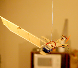
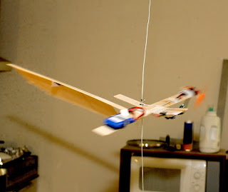
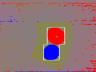
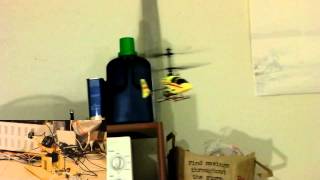
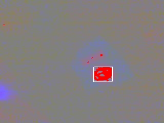
So the 1st flight with some vision hits happened.


 vision27.jpg


Blue becomes visible 1st.

vision28.jpg


Frame is missed, for no reason.

vision29.jpg


vision30.png


The few position data points seemed where they should be, but position sensing wasn't fast enough & she flew right into the ceiling.  Not until the last 4 data points did the autopilot detect a finished takeoff climb.

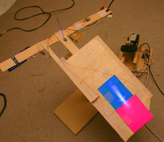
The general idea is the camera needs a complete view of the axis of rotation, so it can have continuous coverage of the red blob during takeoff.  If it can't do that, it needs to get position from a partially obscured red blob, so it can have more data points.  But if it points straight down, it can't detect tilt during takeoff.

marcy2_51.jpg


marcy2_52.jpg


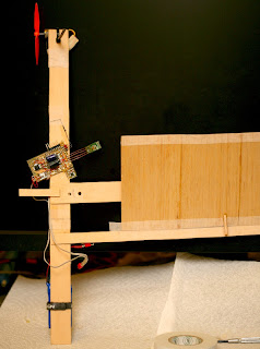
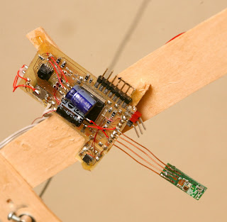
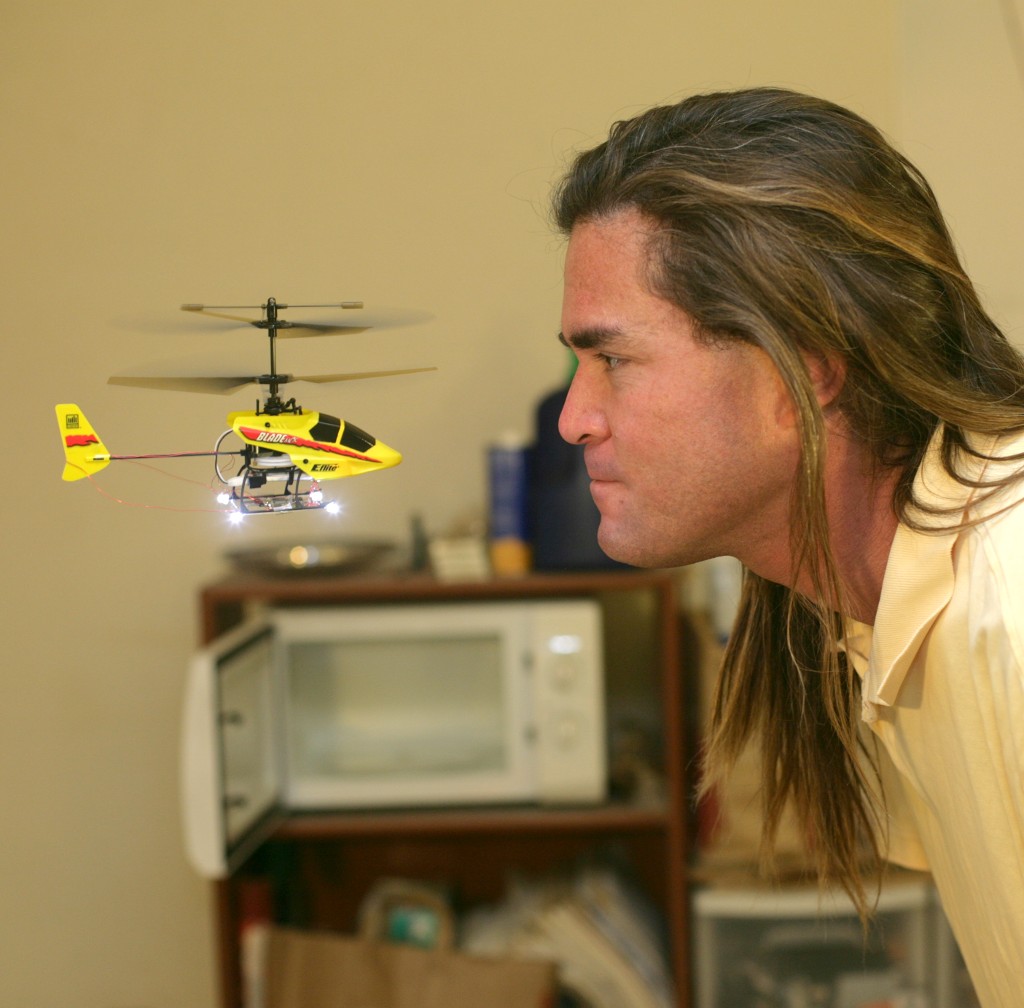
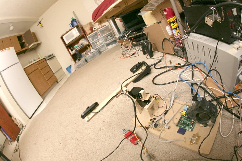
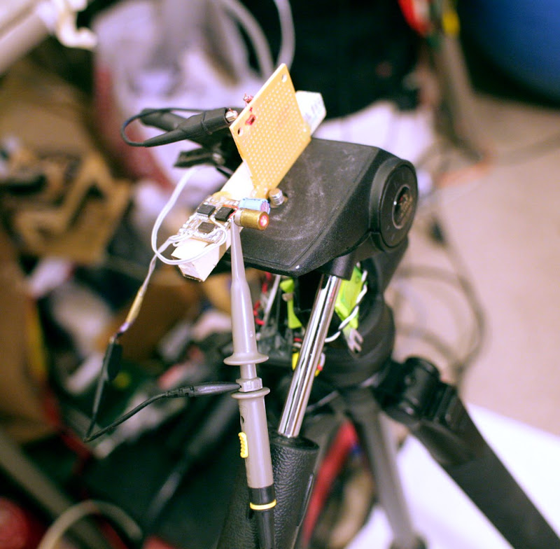
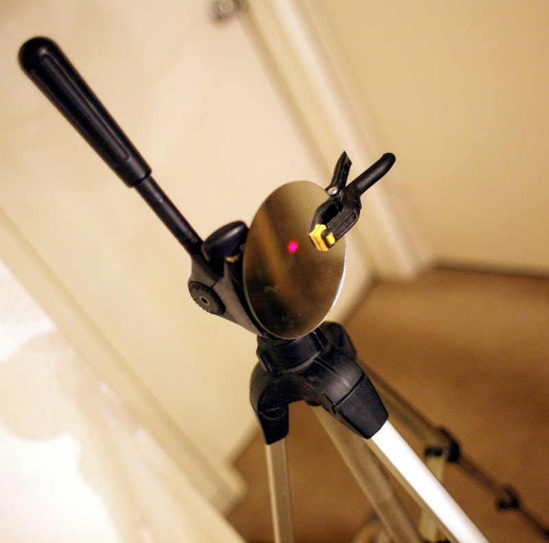
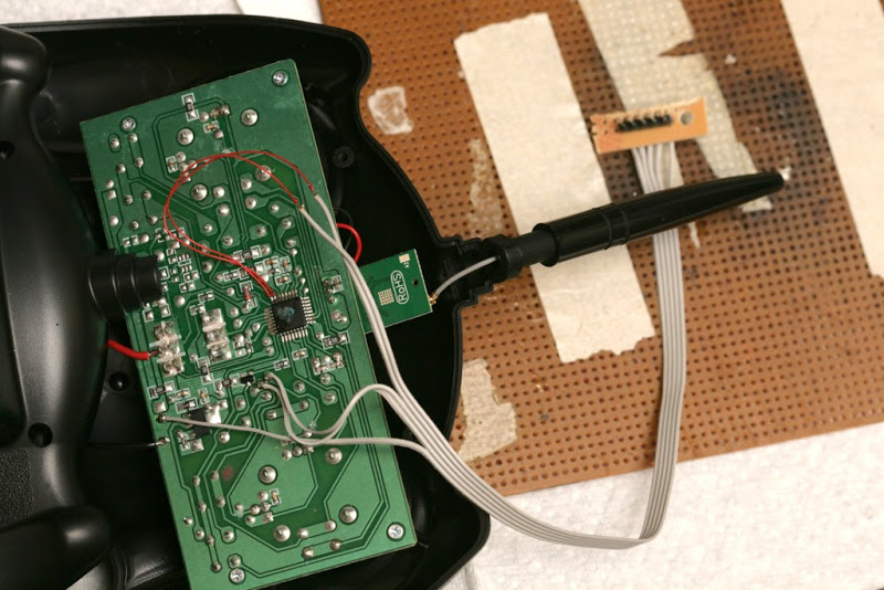
Then came more attempts to get the camera to point down more & withstand crashes.  The wifi dongle seems well protected.  It needs to be as far from the wood as possible, for any reception.

The idea of sonar for altitude & a horizontal camera for position continues to haunt. Exactly how to derive position from the horizontal camera is still unknown.  Feature detection is impossible on it.


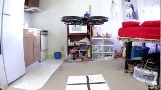
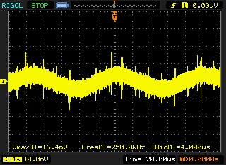
Ground based vision gave Marcy 1 pretty much 10Hz updates.  She spun around at 4Hz, but the incomplete revolutions still seemed to have extra data.

A few more crashes have painted a picture where 1 update per revolution, with many updates glitched out & therefore velocity data based on changing time bases, isn't enough.  Marcy 1 needed many high quality updates to work.  A fisheye lens pointed straight down seems the only way.

marcy2_53.jpg


marcy2_54.jpg


marcy2_55.jpg


marcy2_56.jpg


marcy2_57.jpg


marcy2_58.jpg


marcy2_59.jpg


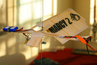
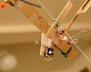
The downward facing camera is slowly rebuilt.  A fisheye lens would solve everything.  Fish eye lenses can physically be produced, but aren't made in enough quantities to be affordable.  So because of a manufacturing technicality, more exotic measures must be tried.

marcy2_60.jpg


marcy2_61.jpg


marcy2_62.jpg


marcy2_63.jpg


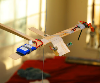
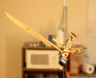
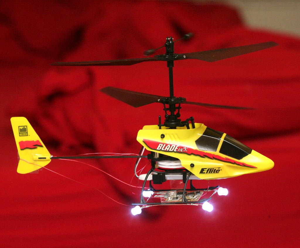
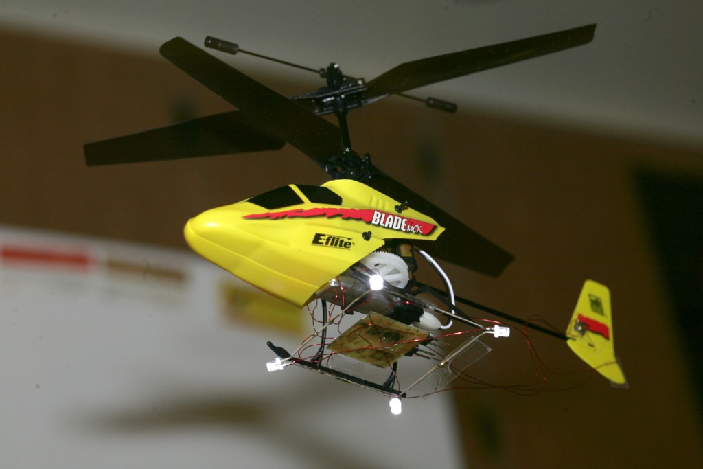
Downward facing attempts continue.  This 1 had more in view, but the camera has a small field of view.

This is quite a heavy attachment, but any payload on it is going to be relatively level for any coning angle.  The options are stuffing it to give it the last angle change, moving mass below it to force it up, or making it rigid.  All this with a field of view which is too narrow.

marcy2_64.jpg


marcy2_65.jpg


Then there's going back to ground based vision, probably feasible with the latest blob detection, but not for any product.  Requiring a target on the floor isn't sellable either, but it was a step towards an all in one system.

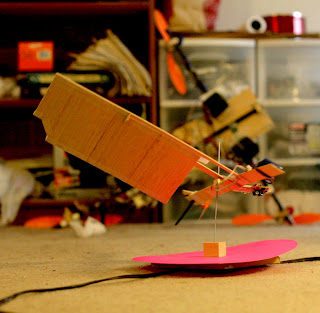
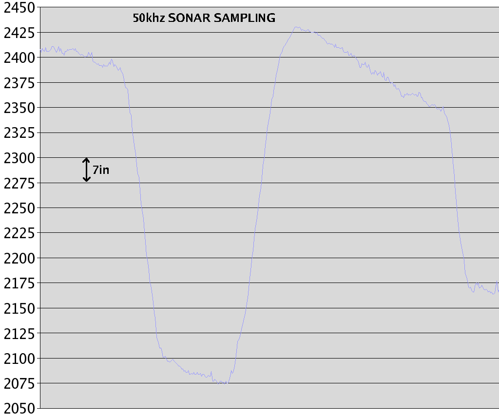
A horizontal firing camera of higher resolution & downward firing sonar for altitude might do it, with this horizontal platform.  The camera would have to detect optical flow of vertical objects.


marcy2_66.jpg


marcy2_67.jpg


vision31.jpg


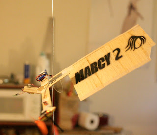
That was as close as anything can be expected to get.  At 2 meters in altitude, there are only 2 target widths of horizontal range.  It's either this & 25Hz position data or diagonally facing & 4Hz position data.

Any vision system that tracks a single object is going to need a gimballed camera.  That's why, even with modern object detecting algorithms, aircraft still only use optical flow.


So aircraft video over wifi was heroic, but only showed it's impractical for navigation.  Pointing sideways, the detail isn't enough to detect motion.  Pointing down, either the field of view is too small or the update rate is too slow.  Even though the rotation rate always created an update rate of 4hz, there was more information in the incomplete rotations.

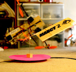
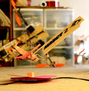
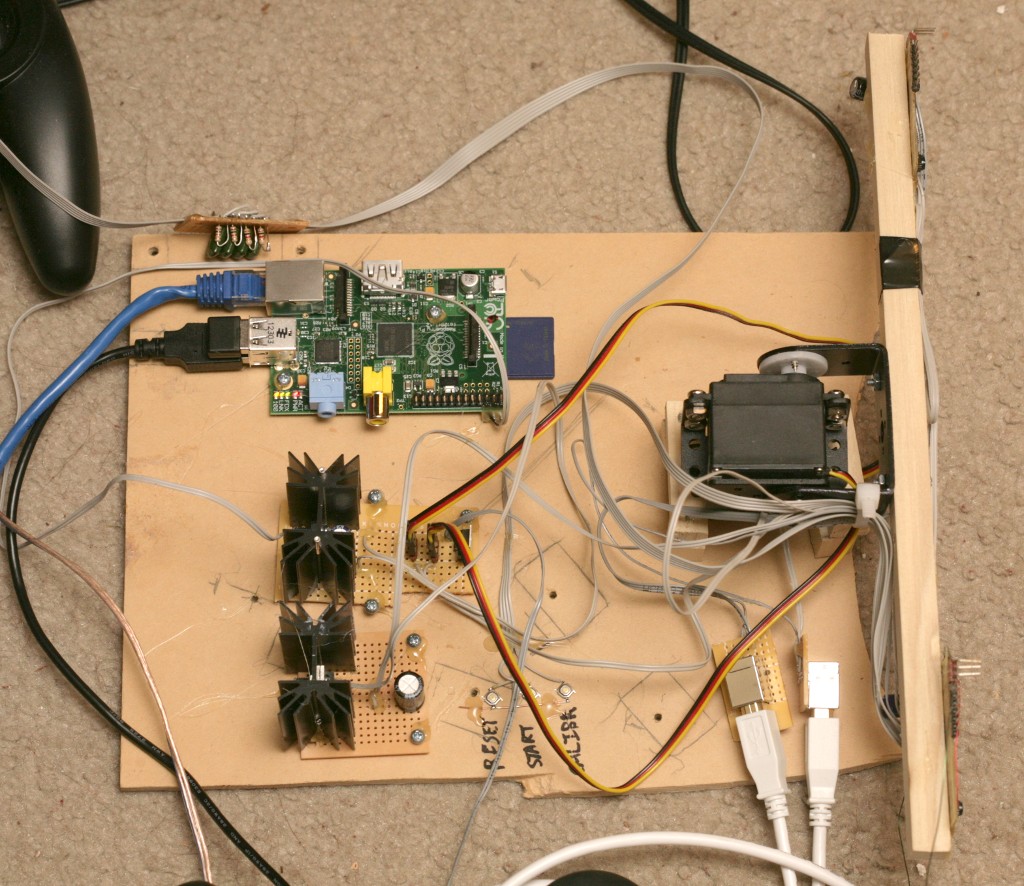
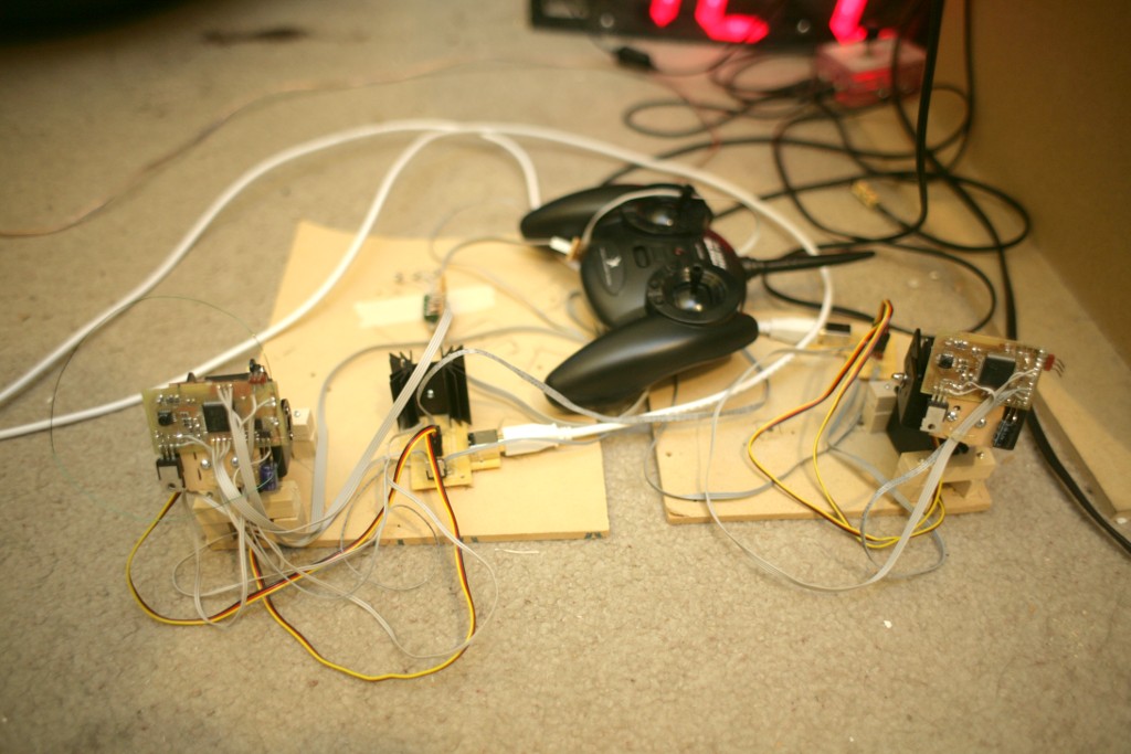
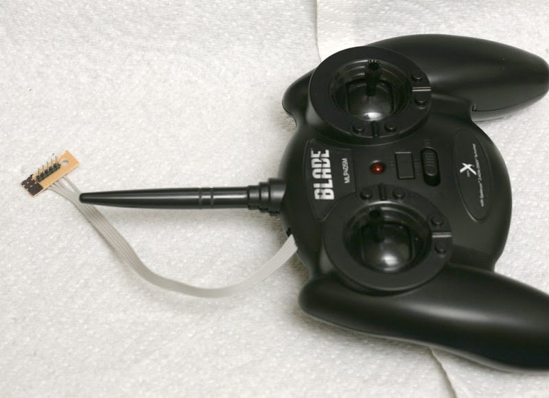
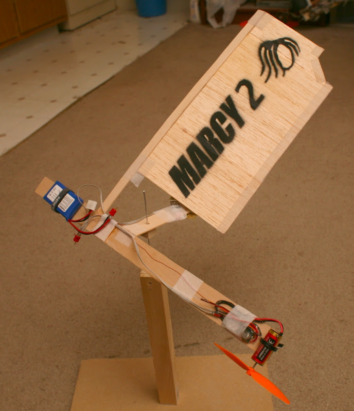
Marcy 2 needs a takeoff platform, so all roads lead to a vertical facing camera pointing up from the takeoff platform.  It's connected by hard USB.  A 2nd camera on the aircraft points sideways & sends video by wifi.  As a simple 4fps video downlink, it would be better done over bluetooth.

It's a lot of wires to connect.  It's not an all in one system, but having both cameras on the aircraft still required a ground target which was bulkier than a ground camera.  Altitude information pointing straight up is not as accurate as pointing sideways.

  1. Thumbnail6:43

    GoPro Digital Hero 3 Disassembly


There's exactly 1 teardown of a gopro hero 3, revealing the wide angle lens

gopro.jpg


is a box screwed down over the sensor, like a webcam.

 Another teardown of this thing
cam07.jpg


revealed a compound lens, like the TCM8230MD.

cam08.jpg


No part number.

cam09.jpg
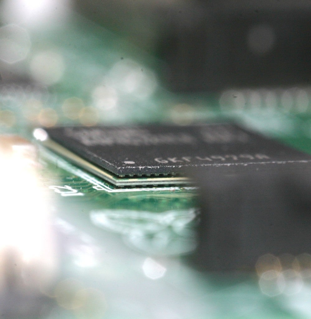
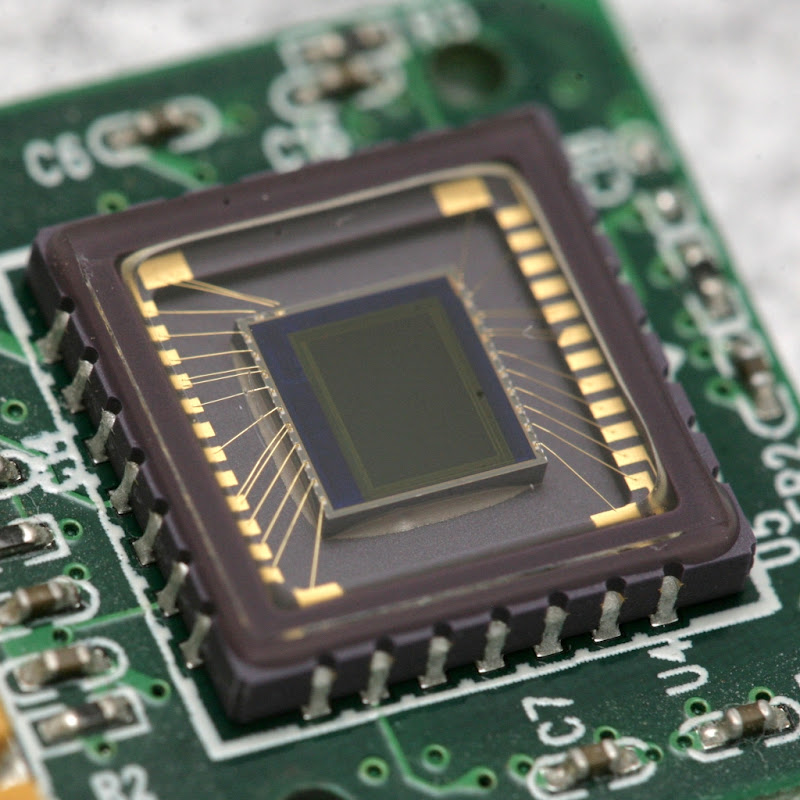
  Another look at the omnivision sensor.


So the keyword that gets lenses to show up is "board camera lens".  Wide angles don't become possible until the sensor is 1/3".

http://www.vitekcctv.com

is the only supplier.  The keyword used to look up cheap, zoomless, fixed focus cams like the gopro is "board camera."

cam10.jpg


A $30 wide angle adapter gets it wider.


peephole03.jpg


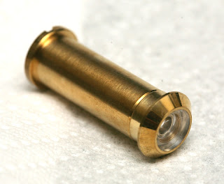
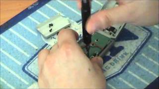
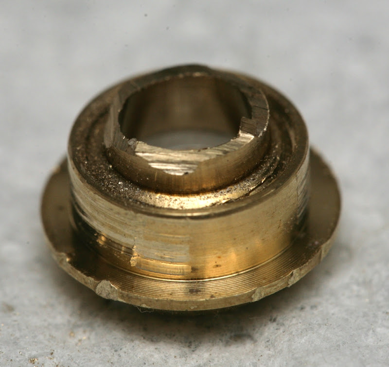
Finally, from goo tube wide angle lens lore, we have the peephole.


peephole04.jpg


It has 2 lens elements.  It splits in 2.

peephole01.jpg


 revealing a useless image.

peephole07.jpg


peephole06.jpg


peephole05.jpg


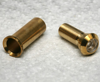
The front element can be ground off.

peephole02.jpg


Revealing no image.


Forget about extracting the 2 lens elements & making a custom tube.  Even when you're done grinding, they're glued in there.


Position sensing from the launch pad is the new ideal.  Attitude leveling for takeoff would be done by a side firing, onboard camera.  The problem of 2 onboard cameras goes away.

Then the problem of position sensing in daylight returns.  Should a cable connect to the launch pad?  Should the launch pad & aircraft both be on wifi?  Should the aircraft use proprietary radio to talk to the launch pad & the launch pad use a cable or wifi?  Should the launch pad use a stock webcam with a USB multiplexer or a custom cam?  What kind of servos should it use?

There's docking a phone to the launch pad to control it & having another remote control, like the Swivl.  There's doing all the navigation processing on the launch pad, having a proprietary radio from the launch pad to the aircraft & wifi from the aircraft to the phone.


marcy2_68.jpg


A few hours reinstalling LED markers returned the reality of colored LEDs saturating the sensor to white.  Then came the realization that Vicon uses reflective markers to keep the sensor from saturating white.  To illuminate the markers, it has a very expensive & labor intensive ring of IR LEDs.

An attempt to light the markers with camera LEDs failed.  Obviously the Vicon cameras can't sense anything too close.  A dreaded infrared camera with ring of LEDs draws nearer.


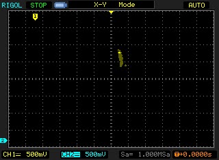
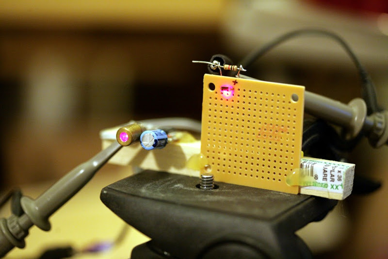
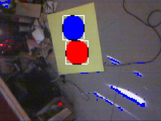
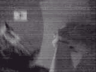
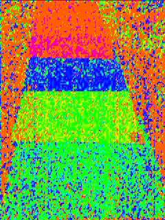
The LED rearranging yielded this.

vision32.jpg


Which the computer sees as

vision33.jpg


or

vision34.jpg


depending on camera exposure.  It's hard to see a future in the webcam business.

vision35.jpg


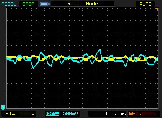
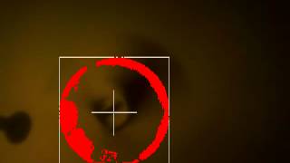
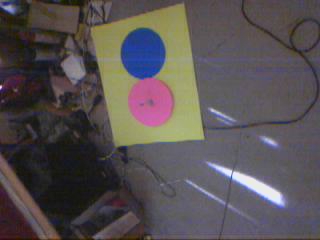
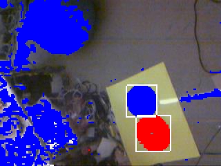
With minimum gain on the webcam & some chroma keying, an algorithm starts to emerge, where the intersections of red, white, & blue are plotted & averaged to give a very accurate location of the marker.


Let's get clear that I did dream about trying to get into Aerovironment.  It turned into the hippy colony from Martha Marcy May Marlene.  The creepy skinny guy was the boss.  He seemed normal, then turned into a crazy preacher of some kind, conjuring up super powers. A crazy dog came out from a wall.  Then there were crazy zombies which mutated into other forms of life.  I didn't care & still wanted the job, hoping the craziness didn't happen during business hours.
3689464139?profile=original
Anyways, the point is 1 of the mane drivers of open source work is the saying "If I can't have a job, no-one can."  You may not realize it, but the simplest answer is always right.
3689464139?profile=original
You think a college student in Finland, a country like US, with total unemployment in 1990, wasn't at least partly driven by vengence because he once sent a resume to work on Minix & got rejected?  I say vengence over denied opportunities has always been 99% of the motivation behind free software, even more than fame or learning.
3689464139?profile=original
It has always been the case that the most valuable work is not what anyone is hiring for.  In 2000, the most valuable work was in video software, yet all the jobs were in e-commerce software.  They specifically wanted to see e-commerce on the resume or you were out.
3689464139?profile=original


A lot of college students then wrote free video editors.  Our motto was if we couldn't get jobs doing it, we'd put everyone out of business who did.  Write the software we did & out of business the corporations went.
3689464139?profile=original
It feels the same way, today.  All the money seems to be in physical computing that combines software & hardware.  It's obvious that you can't make money selling pure software, yet all the companies are still in this 20 year old model of dividing jobs into specifically software or specifically hardware.  If you're not specifically doing 1 thing, you're out.
3689464139?profile=original

So the mission has been if we can't make money because we don't fit the cookie cutter model of pure software engineers with exactly the right 8 year degree in reverse polish turkey notation, produce all the stuff for free until no-one can make money.
3689464139?profile=original

The job market today isn't just bad, the people who are getting jobs are clueless.  It's 1 of those times when it's so bad, people with jobs are more afraid of getting pushed out than increasing production, so they're only hiring lower levels of talent.  The incompetent workforce is begetting greater incompetence.

3689464139?profile=original


If you've got 100 million people whose cost of producing anything is $0 & who are being denied opportunities not because of talent but simply because of fear, 0 is going to be the fair market value for anything produced.  No business will be left standing.


Read more…

Blob vision

 
It does work on the test stand, for the most part. There's a lot of lag. There's a dead area directly on the axis of rotation. The range of working ambient light is very narrow. The mane limitation is not knowing where the axis of rotation is in the frame.

 
vision17.png
  The altitude was manely unaffected by bank.  X & Y were pretty bad.  There is an oscillation from the rotation.  If 1 frame per rotation is counted instead of the 3 in which the blob is visible, the oscillation would go away, but fewer data points would be averaged.
  X & Y seemed roughly aligned with magnetic N.  Further alignment would require stabilizing the test attitude.
 

marcy2_49.jpg


The mane event was devising every possible test for position sensing.  Position sensing from a rotating camera & all the trigonometry required was too crazy to believe it would work.  There were a lot of electronic dongles hanging in mid air.  Crashing would get expensive.

When Marcy 2 was originally conceived, there was full confidence that everything currently on the air frame was physically enough to do the job.  Confidence wanes when it's built up & sitting on the test stand.

The leading technique was the old ceiling hung wire, but it didn't constrain bank angle.  As expected, the bank angle drastically impaired position sensing.  When level, the azimuth correlation & blob detection seemed to work.

There were a lot of obvious glitches which the deglitching couldn't handle.  The camera detected noise as the target when pointing away from the target.

Thus, the error prone test of a minimum blob size was required.  Manely, the largest blob in the last revolution was taken.  Then, all blobs below half its size were excluded.  A blob greater than 1/2 the maximum could sneak in when the camera was pointed away, for which deglitching would be required.  A real paranoid filter could take only the largest blob from the last revolution.

She already has trouble differentiating from the Heroine Clock.  This is the reality of machine vision.

marcy2_50.jpg

The quest for a more robust electronics arrangement continues.  The mane board can be repaired, but the wifi card has a $5 tag & works better near the axis of rotation.

Fly & crash she did.
vision18.jpg
 Revealing no useful position information during the flight.  The takeoff attitude hold was so accurate, it kept the target halfway off the screen during the complete flight. All the energy getting the camera to view the axis of rotation didn't get enough of it in view to give a target.
  The attitude hold stays active until the takeoff altitude is reached, just like ground based vision.  Only then does it switch to position hold.  It's probably acceptable if the takeoff altitude is low.
The current blob won't do.
vision19.jpg

vision000100.jpg

Then there were 2 markers.  Sunlight caused some blue in the chromatic aberration. 

Having 2 markers creates a lot of possibilities.  The overlap of the 2 markers can be used to throw out false blobs, but also eliminates some real blobs.  The distance between the 2 markers & size of the 2nd marker can give a better distance measurement, but the distance is affected by rolling shutter.  The blue marker can be visible sooner in the takeoff.


You can see how more targets could be added & detected based on proximity.  Then, the position could be even more refined.

Of course, blue immediately showed the same horror glitches it did before.  Light blue might work better, but it's not mass produced.  Maybe if all blobs were thrown out that weren't a red & blue next to each other.

That was disappointing, but there's hope some simple shape detection is possible or some redundant marker can work in the 1st moments of takeoff.  Such a diabolically complicated system like that brings to mind the idea of detecting position from a partially obscured blob.

The radius & center can be derived from the dimensions of the rectangle.  But that also depends on rolling shutter.

A 2nd pink circle would be hard to separate from the 1st.  Enough testing could define a minimum distance to resolve the 2.  Then they could be mounted on a blue background, guaranteed to not generate a false positive.  How would it know where the maximum distance between the 2 blobs ended & ambient noise began?

It could measure the size of the small blob & compare it to the distance from the big blob. 

vision20.jpg

The small blob isn't big enough to get any size & if only the small blob is visible, it'll trigger a false positive.  The scanline compression takes away a lot of photons.  Some rough, procedural shape detection may be the only way.


vision21.jpg


A line was also worthless.   At flight speed, it takes a lot of photons to trigger the mask.

vision22.jpg


Blob matching based on overlapping boundary boxes of the red & blue got rid of some pretty significant blue noise.  Boundary boxes aren't as robust as scanning every red pixel for a neighboring blue, but faster.

vision24.jpg


The final attempt in this red/blue combination was scanning every red blob pixel for adjacent blue pixels & taking the largest blue blob.  This was bulletproof at separating the red/blue marker from the noise.

It was a leap in intelligence, actually detecting details in a noisy image from a spinning camera, with complicated rules for switching to the blue blob when the red blob was obscured & throwing out all red blobs without an adjacent blue blob, except during takeoff. 

vision25.png


Surprisingly, the blue & red blobs seemed to give very consistent results, right down to Y offset between blobs.


In the worst case, 1 original plan if the camera couldn't look straight down was to have the red off center for all position sensing & the blue for the takeoff leveling with a new requirement to not hover directly over the red.

vision26.jpg


Another test flight & another crash as the denoising algorithm throws out good data.  If the aircraft rises too fast & the blobs get small too fast, they get thrown out for being too small.

There were only 20 good frames it could have used during the takeoff, if it worked.   


Anyways, started thinking more about tethered power.  The 10 minute flight time & cost of crashing batteries over the years is such a turnoff, it makes you think surely the infinite flight time of a tethered system can outweigh the drawbacks.

It's been sold before as a finished product, with limited results.  Maybe it was sold to the wrong customers.  Someone interested in a flying camera for photographing on a closed set would be better off with a tethered system.  Hobbyists are manely interested in hovering a camera in a stationary location.

The mane limitation of all FPV videos is they have a very limited horizontal range, beyond which they always have to turn around.  It's hardly enough justification for batteries.

The ideal tethering system has an insulated wire for V+ & uninsulated wire for ground.  The wires are as thin as possible.  The voltage on the ground is much higher than the motor voltage, to compensate for resistance.  The motors are wound for very high voltage & low current.

The monocopters can't be tethered.

Read more…

The future is pink


 Marcy 2 finally does the 1st step in flight: stabilized rotation on the ground, using the onboard camera & blob detection. Making the RPM slow enough for maximum efficiency makes it too unstable to take off without active control.

It took only 1 week for the super simple ESC to arrive from Hobbyking.  The way to deal with them is to break up an order into segments small enough to ship in 1 week.  Instead of 10 motors on the 4 week shipping plan, create 10 orders on the 1 week shipping plan.

marcy2_48.jpg
  The evolution of optical targets continues.

It could be passively stable, with landing gear, higher RPM, & more weight.

For now, the lighting is provided by 150W CFL's.

 Next is the hard part: detecting position from the onboard camera in flight.  Exactly how to test it is the hard part.  Coning angle & RPM change depending on altitude & payload.

 In other news, there have been some ideas of going back to ground based vision for Marcy 2 & having a higher quality airborne camera just for viewing.  Blob detection might be good enough to get ground based vision to work in ambient light.
 The ground based camera is smaller than the ground based target & the payload is lighter.  2 cameras on the aircraft for navigation & aerial images are unlikely because of the CPU load.  It would take another chip to serialize the data from 1 camera.
 There's no way to envision 2 cameras with a single chip, but the ground based vision takes a lot more money.  The ground based camera needs the 2 servos & a lot more fabrication than the target & both options need a takeoff stand.
Aerial vision is having real problems with inconsistent light.  Takeoff happens on the ground, so the ground is covered in a shadow.  There are taller takeoff rods.  LEDs don't do white.  They either make everything blue or red.  Only CFL lights produce a real white which can differentiate between red & blue.
There's always requiring the user to fly in a well lit area & lighting the takeoff area with red LEDs.  Most interiors are very dim.  People keep their windows closed & use 60W lights, especially single people.


 The mighty flood fill algorithm from 1980's PC Paint makes another appearance in Marcy 2's blob detection algorithm. It's normally instantaneous with a 160x240 image, but here it has to flood fill hundreds of blob candidates in each image, then take the largest blob. That's very slow.  After much optimization, 25fps of 160x240 takes 10% of a 3.8Ghz processor.

The Marcy 2 algorithm separates a marker from a background with changing viewing angle & lots of noise. Here it's shown separating markers from a lion. The camera is configured to only capture hue & saturation, to reduce the JPEG compression load on the microcontroller.

There was a blob tracking demo in OpenCV, with undoubtedly the same algorithm, somewhere. The demo only seemed to show a difference algorithm with a static background. There wasn't any documentation for any other blob tracker, & 10MB is a bit large for a blob tracking library.
There is a camshift algorithm in OpenCV which might do a better job.  The algorithms have usually not been precise or reliable enough to fly something.  There's a big change going from a Willow Garage robot which takes 30 seconds to move an arm to an unstable aircraft which needs precise, reliable data 4 times a second to avoid crashing.  You also have to be under 25 to use OpenCV.

URB_ERROR resolved

So the mighty USB problem of 3 months was narrowed down to a toggle error, meaning a packet was dropped. No surprise, since it was always the 1st 64 bytes of an 802.11 frame that were missing.

The improvement after keeping the bus busy was because the packets were all multiples of 64 bytes, not the bandwidth.

The breakthrough was noticing the errors only came after packets which were even multiples of 64 bytes.  A hack to only flip the toggle bit after packets of odd multiples of 64 bytes fixed the great stm32f407  URB_ERROR problem.


It was a single line in USB_OTG_USBH_handle_hc_n_In_ISR:

       if(((pdev->host.XferCnt[num] + 64) / 64) % 2)
          pdev->host.hc[num].toggle_in ^= 1;


Ping then became 100% successful, manely limited by RF glitches.  No lockups anywhere, no URB errors, & the promise of full wifi with the microcontroller was finally realized until the next microcontroller comes out.

While simultaneous send & receive still isn't possible, it's not necessary for any of Marcy 2's requirements.

ip02.png


ip03


That was a lot of work & a waste of time.  The Wifi settings could have been changed with a much faster ground station protocol.  There's no desire to implement packet spanning in the http protocol.  There's just enough space in a single packet to handle all the configuration pages.

The USB limitations make it impossible to time out while waiting for an ACK, so TCP over wireless is really clunky & doesn't promote a lot of confidence in putting $100 of parts in the air.  The UDP protocol for flight control is bulletproof, but psychological impressions come from TCP.

It's yet another interface to worry about.  The web server only came up because it's the 1st place people think of for configuring the wifi parameters.

DNS & TCP need to be hidden features, enabled by a buried option in the ground station.  A jumper across 2 pins will be required for resetting to factory defaults.  A key for you web based wifi configuration coders: disable the motor until reboot.

ip01.png


The Marcy 2 router package is as complete as can be.  Up to 8 stations are supported.  They can't do anything besides ping, flight control, & the web based configuration.


You should be aware that EVERYONE is in a race to build the 1st personal flying droid.  The winner will happen when the 1st personal position system that actually works appears, setting all 500 of you UAV entrepreneurs off on 30 endless nights promoting your kickstarter accounts, ordering your sparkfun parts, & getting the thing working.

The leading candidates are now based on vision.  The radio, sonar, GPS, & lidar contenders all have problems.  1 thing you may not have thought of is for a personal droid, flying within 10ft of the user, battery power isn't always required.

If it's hovering near someone exercising or shooting video of a talking head in a defined space, it can be tethered.  Tethering gives an element of infinite loitering time that your inductive charging stations can't match.

Quad rotors still seem too expensive to penetrate the mass market.  Those 12x30mm brushless motors are never going to be produced in enough quantities to meet demand while those 7x16.5mm brushed motors don't last long enough. 

Read more…

Home made ESC ideas

marcy2_44.jpg


Bodge work continues, in the pursuit of supplying the required current in the smallest possible space.  The LM1117 was the only thing available locally.  It makes 3.25V at 800mA with a 1.3V dropout & no other components.  A single one wasn't enough.

The double stack still got hot enough to burn a human.  Meeting the size & weight requirements makes for some bleeding edge temperatures.

marcy2_45.jpg


That ended up failing after a few minutes, leading back to the old TO-220.

marcy2_46.jpg


It would be a lot cheaper to calculate the required current, voltage drop, thermal dissipation of the board, & get the exact right part.

marcy2_47.jpg


Once you start pouring out heat to get the required power in the required space, the hot glue starts melting.  This has become disastrous in sunlight.  A hotter hot glue is required.

Anyways, after some time chasing after the lack of motor pulsing on Marcy 2, found the Castle Creations 6 is giving different results than the Castle Creations 9.  1 of the mane reasons people design their own ESC's is these inconsistencies.  Response rate, maximum duty cycle, different deglitching algorithms are the mane problems. They all accept 200Hz.  The deglitching may slow down the response rate.

Every ESC over 6A gave instant response, including Castle Creations & Hobbyking.  The leading theory is overloading, causing it to pull back when the throttle change is too big.  The 6A hesitates during throttle increases while the 9A instantly spins up.  Castle Creations are too expensive to buy another 9A & the 10A from Hobbyking takes 1 month to deliver. 

Was surprised to find 3drobotics does not sell an open source ESC as rumored.  They sell a 20A m2mpower ESC.

The mikrokopter ESC is the only complete source code & very specific about not being licensed for commercial use.

There is an SIlabs reference design.  It's quite simple.

The fact is you can't undercut hobbyking, which makes any home made ESC fruitless. 


The lack of an ESC & no desire to break down Marcy 1 for her ESC led to implementing things which make Marcy 2 a product more than a science project, manely a full router stack.  ARP, ICMP, DHCP, & DNS were the big ones.  The mane dictator over all this is the high USB error rate, causing many packets to be lost.

ip01.png

DNS was a real painful implementation of a luxury.  It destroys the realtime performance.  It's too slow to ever be used, but a host name looks neater in a ping command than an address.

Marcy 2 takes your computer off the internet & puts you on her own isolated network in domain heroinewarrior.com.

The access point now supports 8 stations, with flight control possible from any IP address.  In the battle of the router, DNS was voted off the stack.  It worked, but was the only protocol which had response packet length determined by the user.  Some packet lengths caused yet another USB crash.  So DNS now sends a fixed size response.  If the domain name is too big, it's truncated.

Even without that crash, the URB_ERRORs make all the protocols unbearably slow.  ASSOC, DHCP, & ARP are pretty bad but only happen once.  The only way to make the experience fast enough is to limit communication to the flight protocol.  There's no way to have a web page for configuration.

The URB_ERRORs on the STM32F4 drop when the pipeline is kept busy.  In full operation, streaming 2 megabit video, there are almost no errors & the IP stack always works.  Another method is to poll the interrupt endpoint graciously provided by the RTL8192.  This always returns immediately.  The interrupts are absolutely useless, but they keep the pipeline busy enough to reduce the errors.

Sort of disappointing to go through all the trouble of supporting a USB dongle only to have it be incapable of basic IP protocols.  Since the USB core on the STM32F4 is a stock core from Synopsis, there's always hope it really works, but so far it still seems intended for a mass storage device, where the reads are always guaranteed to happen right after a write.


The money for a smartphone is still too far off.  All roads are now leading to iOS & then porting to Android when iOS usage falls off.  It's unavoidable, since iOS is the only thing which is guaranteed to work.  Android has zillions of incompatible pieces of hardware.

The real problem is how iOS is only supported on 2 gadgets: 1 phone & 1 tablet, each updated only once a year.

Read more…

Downward facing camera

marcy2_37.jpg

marcy2_38.jpg

marcy2_39.jpg

marcy2_40.jpg

marcy2_41.jpg


The 1st attempts to point the camera straight down were failures.  It can be pointed straight down & it gets the same target in every frame, but these arrangements screwed up either the starting pin or the center of gravity.

It became obvious that the propeller had to thrust on the plane of the center of gravity for the most stability, so all the electronics had to be in the same plane.


Having the wing below the plane hindered all the Marcy class.  Part of the coning angle would be the center of gravity in the wing lifting into the plane of motor thrust.  At  least this showed a winglet should add more stability than a dead weight, by having more mass in the motor plane.

images09


So that was the axial pointing camera revealing new rolling shutter distortion.  Instead of uniform vertical squishing, the top right had stretching & the bottom left had squishing, in both directions.  That is correctable, by knowing the rotation rate & scan rate.

marcy2_42.jpg

marcy2_43.jpg


This was the best arrangement.  Moving it from the wing to the balance beam got the Y axis on the camera to always be parallel with the spin axis.  If the camera was on the opposite side of the spin axis from the wing & on the balance beam, its field of view in its X axis would cover the spin axis instead of looking away from it & its Y axis would always be straight down.

cam85.png


So the camera could look straight down the spin axis just by repositioning it on the plane of rotation instead of building a diagonal harness. 

images10.jpg


Also noticed there was a good chance the attitude could be determined by looking at the takeoff stand's position in the frame.


Anyways, object recognition with SURF was worthless on the 160x240 video.  There seems to be a minimum complexity before SURF detects a feature point.  The resolution isn't high enough to hit that minimum complexity.

images11.jpg

images12.jpg


At flight altitude, the marker is gone.  The AR Drone required much higher resolution just for detecting velocity.

With the camera pointing at the floor, there might be a future in chroma keying.  The floor is more uniform than the ceiling.


Marcy 2 would require covering a large area of the floor in markers.  The field of view is too narrow for a single marker.  A simple grid with different codes in each square would do it.  A flashing laser projected from the aircraft, off axis from the spin axis, might give altitude.  Sonar altitude is too expensive.

 With the camera limitations & frame rates now well known, any kind of object recognition was ruled out.  The only real option was what it was on Marcy 1: color based blob detection.


chroma


Setting the camera to only record chroma reveals it detects RGB.  Yellow doesn't show up at all.  Some fluorescent pink posterboard showed up nicely. 

chroma02.jpg


Even with it pointing down at a featureless floor, chroma keying was still a problem.

chroma03.jpg

chroma04.jpg

The onboard camera didn't work as well as the DSLR.  It was in chroma-only mode to get enough information to do chroma keying at 25fps.  The color resolution was 160x240 & the hardware saturation was at maximum, which still allowed a lot of saturation changes.

Surprising how well the blue came out.  Humans must not see it as well as cameras.  Yet it detected pink better than red.


Saturation & hue were still being captured.  Maybe it would go faster if just the hue was captured.

chroma05.jpg


Plotting all the possible chroma values, a 256x256 lookup table emerged, in which chroma was converted to hue.

chroma06.jpg


The result was such a noisy image, it actually increased the bitrate & sent the framerate down to 15.  Not the intended result.

What looks like more differentiation between green & background, the computer actually didn't notice. It still detected the least differentiation with green & the most differentiation with pink.


Anyways, some tests with OpenCV blob detection didn't work.  That requires some training data, which they don't give an example of.  Camshift showed pretty good results.  Red, yellow, & blue showed good separation from the background.  The camshift algorithm has a good detection step for getting the size of the object.

The mane problem is it takes lots of tweeking.  Manual white balance was a must.  Also, it did best with the full RGB data instead of just the chroma.

Full RGB limits you to 80x120 for the chroma & 160x240 for the luminance.  160x240 with full frames buffered, full chroma resolution, & dropped frames started looking pretty tempting.

Read more…