All Posts (14029)

Sort by

We are excited to announce our latest FlytBase release, a significant step forward in enhancing drone operation control, expanding functionalities, and offering advanced solutions for aerial data capture and analysis. Key highlights include the integration of the Thrustmaster joystick, renowned for its precision and ergonomic design, which revolutionizes drone and payload control in remote setups.

Additionally, we introduce Payload 2.0, advancing your drone's thermal imaging and sensing capabilities, and our innovative Live Map Annotations, designed to improve mapping, navigation, and team collaboration.

Thrustmaster Joystick Support

Central to this update is our integration with the Thrustmaster joystick, specifically the Thrustmaster T.16000M Space Sim Duo Stick, known for its precision control and ergonomic design. This integration transforms the way operators control both the drone and its payload in a remote setup, providing:

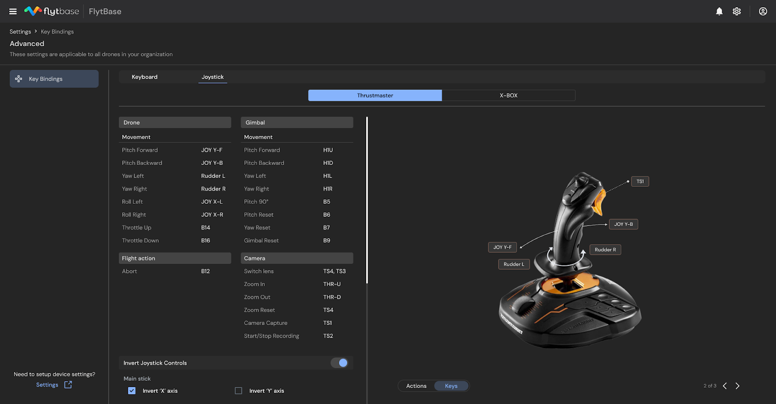
  • Precision Control: The joystick's multiple axes, buttons, and programmable triggers enable operators to navigate drones with unprecedented accuracy, essential for executing complex tasks and navigating challenging terrains.
  • Improved Maneuverability: The ergonomic design and intuitive interface of the joystick facilitate smooth and precise flight patterns, making it ideal for detailed inspections and operations in demanding environments.
  • Revamped Key Bindings: To further personalize the flying experience, we have redesigned the Keyboard and Joystick Bindings Settings, allowing operators to tailor their control setup to their unique styles and preferences, ensuring smoother and more efficient manual flight operations.

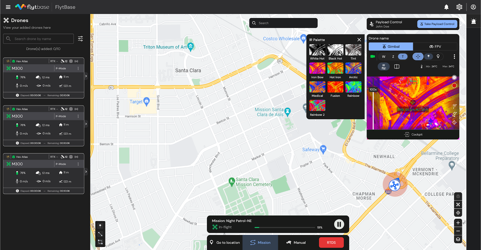
Payload 2.0: Advanced Thermal Imaging and Sensing

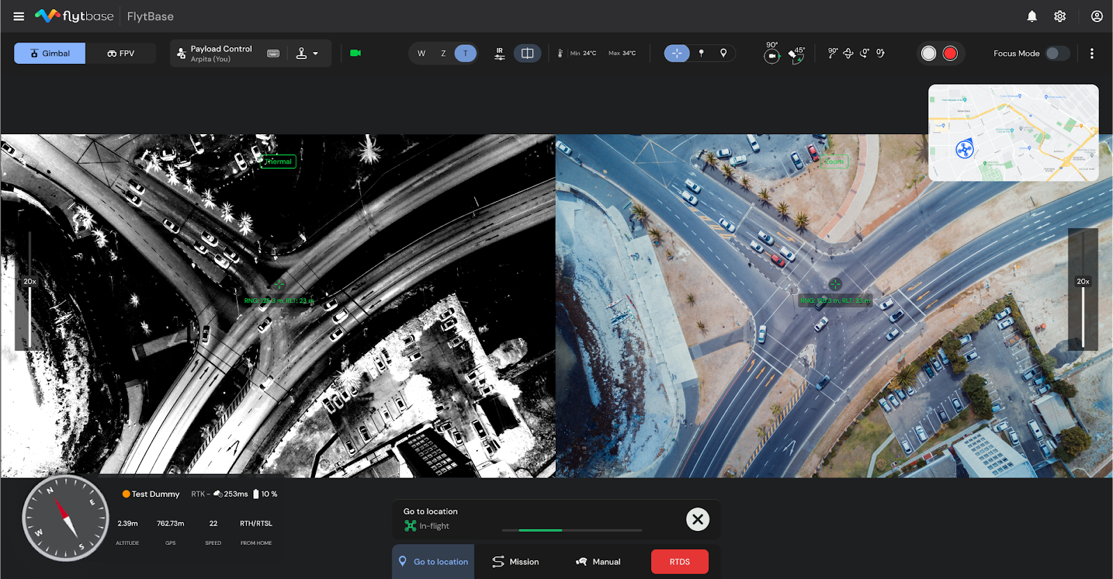
Payload 2.0, brings a significant enhancement to your drone's thermal imaging and sensing capabilities. This update is particularly exciting due to the integration of the DJI M30 range finder, along with advanced thermal palettes and a split-screen display -offering a dual perspective, crucial for in-depth environmental assessment and decision-making.

  • Versatile Thermal Imaging: With the integration of the DJI M30s thermal palettes, operators can now select from a range of imaging options to best suit the specific requirements of their mission. This versatility is invaluable in operations such as search and rescue, infrastructure inspections, and environmental monitoring, where clarity and precision in data interpretation are paramount.


  • Dual Camera Mode: Our Side-by-Side (SBS) display feature is a breakthrough in environmental assessment. Operators can now view infrared and visual feeds simultaneously, enabling comprehensive real-time analysis and fostering quicker, more informed decision-making.

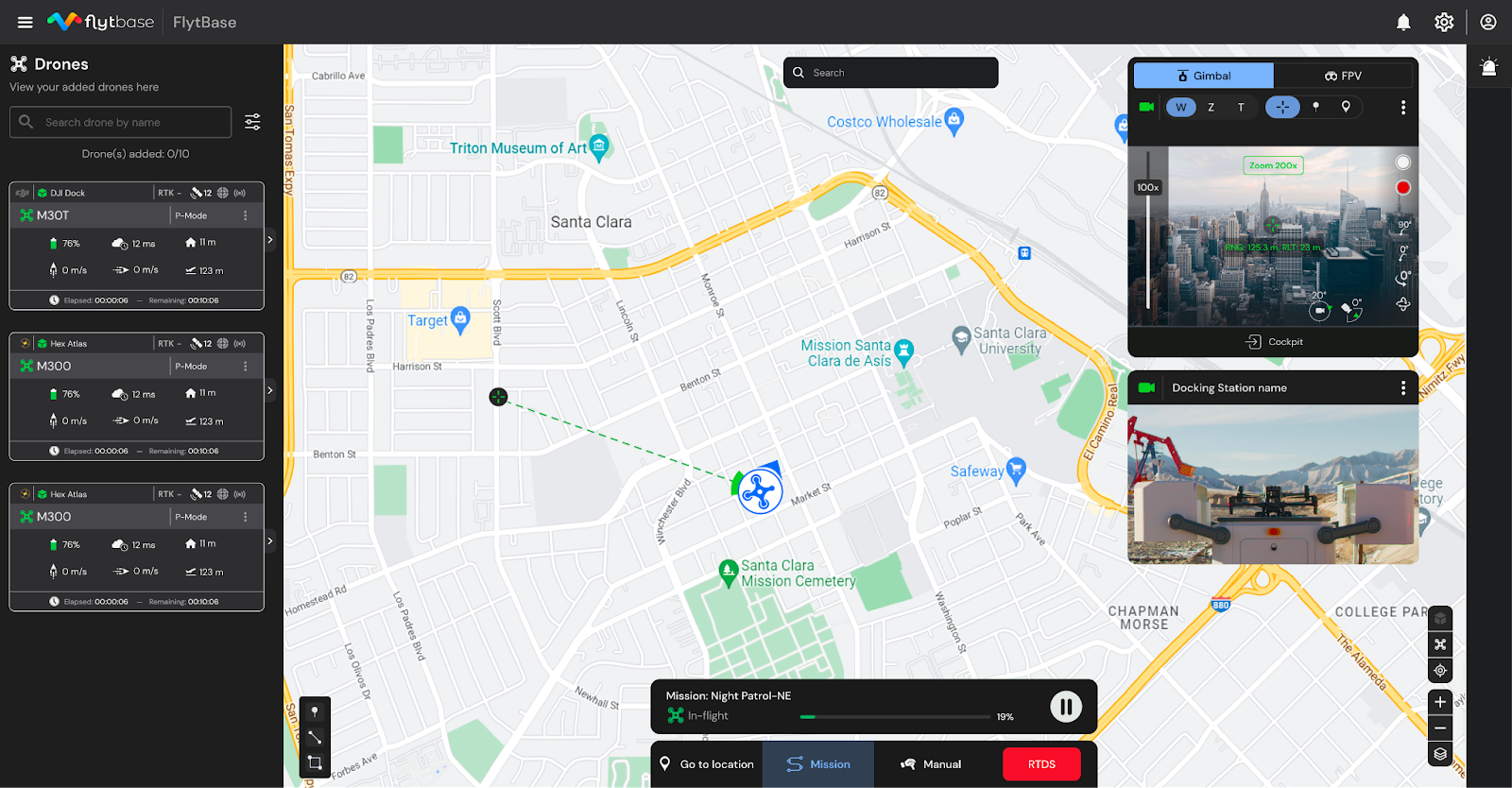
DJI M30 Laser Rangefinder support for Enhanced Spatial Awareness

The integration of the DJI M30s laser rangefinder is another highlight of this release, offering operators exact spatial awareness, a critical factor in conducting precise operations:

  • Instant Location Marking: Operators can now effortlessly mark, share, and revisit coordinates and distances of key locations or objects with a simple click, greatly enhancing operational response time and efficiency.
  • Precise Drone Navigation: Direct your drone to specific coordinates with laser accuracy, a feature that significantly boosts operational effectiveness, especially in complex environments.

Live Map Annotations

Discover our new Live Map Annotations feature, designed to offer versatile, customizable annotation tools for enhanced mapping, precise navigation, and improved team collaboration, ensuring efficient and safe mission execution in various operational scenarios. What’s new:


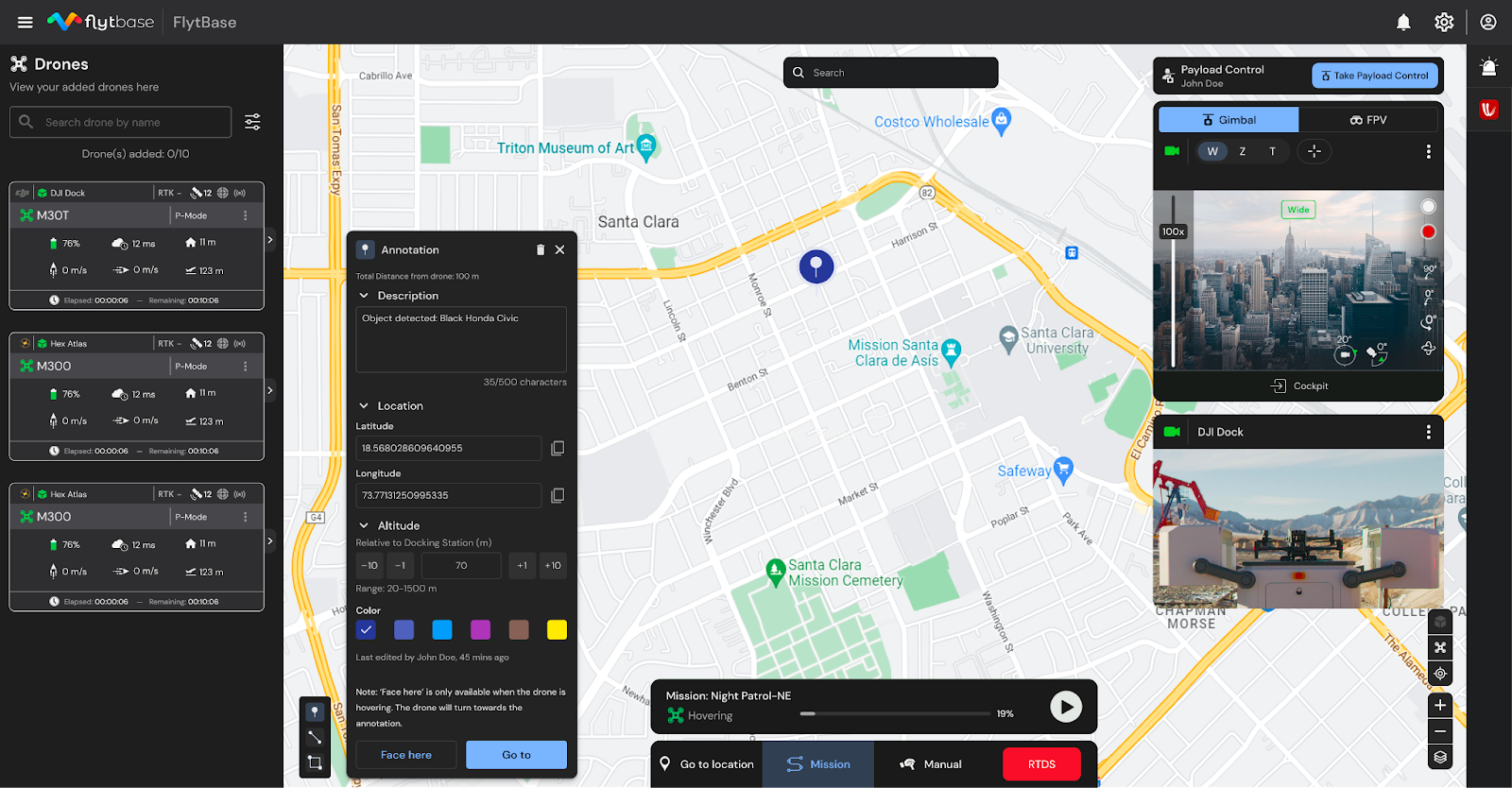
  • Versatile Annotation Tools: Users can create diverse annotations - lines, points, polygons - adaptable for various missions, from search and rescue to infrastructure inspections.
  • Customizable Mapping: Annotations can be customized in color, shape, and position, improving the clarity and relevance of operational maps for better planning and execution.
  • Launch Drone to Annotated Locations: Annotate specific areas on the map, set altitudes, and direct drones to these coordinates, enhancing efficiency and safety in complex environments.
  • Enhanced Precision with Range Finder: The integration of the M30s range finder with Live Map Annotations adds precision, crucial for operations requiring spatial awareness and accurate distance measurements.
  • “Face here” functionality: Mark points on the map for the drone to orient towards automatically, useful for focusing on critical areas. This feature, coupled with the M30s range finder, which displays the distance to these marked points, providing you with a comprehensive view of the drone's position and target location.
  • Streamlined Team Collaboration: Live annotations are visible in a dedicated window and on the map, ensuring swift information sharing and synchronization among team members including owners, admins, pilots, and ground teams.

Learn and Explore More

Learn how to effectively utilize these new features by referring to our in-depth guides on Enhanced Map Annotations and Thrustmaster Joystick Integration.

Dive deeper into FlytBase's extensive capabilities by checking out the FlytBase User Manual.

Have questions or feedback on optimizing your autonomous drone operations? Reach out to our team at support@flytbase.com. We're here to guide you every step of the way!

Read more…

12300231669?profile=RESIZE_710x

Purchase link: https://tmotor.en.made-in-china.com/product/pCOEozjunIcr/China-T-Motor-U8lite-Kv85-Highly-Powerful-BLDC-Motor-for-Quadcopter-Aircraft.html
U8II LITE KV85, T-MOTOR propulsion system, for your drone's safer flight.
Hovering Thrust: 2kg-2.5kg
Quadcopter: 8kg-10kg
Hexacopter: 12kg-15kg
X8 : 12.8kg-16kg


Email: jessica@tmotor.com

Read more…

UAV hand winding BLDC motor T-MOTOR

T-MOTOR Chinese drone motor factory how to make a hand-winding motor for industrial drones

Why does T-MOTOR always insist on some production lines using hand-wound motors when the labor costs are still rising? #drone #manufacturing The hand-wound motor has a higher slot full rate so that the adjustable performance range is wider. The experts will try to fill in as many wires as possible for every motor. However, a machine without the naked eye can't do it. On the other hand, although machine winding leads to higher productivity, hand-wound motors also greatly increase quality control, ensuring that each product goes through multiple inspections to your flight safety.
Lots of people didn't believe that, you can find the answer through the video.

https://www.youtube.com/watch?v=wKIYuEGFKxQ


Read more…

UAV hand winding BLDC motor T-MOTOR

T-MOTOR Chinese drone motor factory how to make a hand-winding motor for industrial drones

Why does T-MOTOR always insist on some production lines using hand-wound motors when the labor costs are still rising? #drone #manufacturing The hand-wound motor has a higher slot full rate so that the adjustable performance range is wider. The experts will try to fill in as many wires as possible for every motor. However, a machine without the naked eye can't do it. On the other hand, although machine winding leads to higher productivity, hand-wound motors also greatly increase quality control, ensuring that each product goes through multiple inspections to your flight safety.
Lots of people didn't believe that, you can find the answer through the video.
12291397267?profile=RESIZE_710x

https://www.youtube.com/watch?v=wKIYuEGFKxQ

Read more…

The VT-Naut is a VTOSL (Vertical Takeoff and Short Landing) fixed-wing drone, an innovative aerial solution meticulously designed to cater to diverse applications, including accurate mapping, surveying, inspection, scouting, observation, and agriculture, with a multitude of payloads that will be offered.

ELEGANT SIMPLICITY
The VTNaut's uncluttered tail-sitter design embodies elegance and simplicity, ensuring optimal performance, unwavering reliability, and cost-effectiveness. This simplicity stands in stark contrast to the complexity and expense associated with alternative VTOL designs, avoiding "dead-weight" throughout its flight stages typical of other tilt rotors or multi-motor configurations.
 
WHY SHORT LANDING INSTEAD OF VERTICAL?
Our two decades of experience operating fixed wing drones indicate that in over 85% of cases, there's ample space for a fixed wing UAV to execute a cost-effective belly landing.
Fixed wing VTOL drones are designed to survey very large areas, so finding an appropriate spot to launch and recover from is almost always easily possible. A "belly landing drone" translates into a lower cost drone design which directly benefits the user.
A vertical landing drone is seldom absolutely necessary unless operating in exceptionally confined spaces such as dense forests or heavily populated areas, and this ability comes at greater cost, both economical and operational. The VTNaut caters to those seeking a cost-effective alternative to a full VTOL platform, who has flexibility for site selection for landing the drone and who requires to survey very large areas.
Moreover, the VT Naut integrates sensors designed to facilitate pinpoint-accurate short landings, minimizing the required landing space.
 
AMPHIBIOUS CAPABILITY
Building on the success of our acclaimed Aeromapper Talon Amphibious, we have expanded our offerings to include an amphibian variant of the VTNaut, enabling safe landings on water, including saltwater bodies. This enhancement positions the VTNaut as the preferred drone for marine or shipboard applications.
 
FEATURES:
• Indestructible materials: thanks to its EPP foam compact body design
• BVLOS: Beyond Visual Line of Sight capable thanks to its 30km data link range
• Multipayload: high resolution for mapping, 4k 3-axis gimbal and multispectral sensors will be announced very soon for the VT-Naut.
• Long Endurance: 90 min endurance. An even longer endurance version is currently in the works.
• Low cost: the VT-Naut will be offered at just a fraction of the cost of a conventional VTOL drones available.
• Remote ID equipped
• Transport Canada compliant status: the paperwork is currently being prepared to submission
• The VT-Naut has been tested for already for 2 years, and its backed by our more than 10 years of experience manufacturing survey grade fixed wing drones, which have been used in more than 60 countries.
 
To stay tuned for official announcement go here
Read more…

Freewing Zeus 90mm EDF Sport ARF Plus Jet RC Airplan

Version Note: This is the ARF+ version for pilots who wish to install their own power system. All primary electronics including servos and landing gear retracts come pre-installed, just add your own power system (EDF, motor, and ESC) to begin flying.

The 90mm Zeus is the latest sport jet offering from Freewing. Featuring a sporty and highly aerodynamic design, the Zeus 90mm is Freewing model,s fastest sport jet yet, reaching speeds of 130 miles per hour (210 kmh) in level flight. Additionally, the blue, grey and white livery offers an attractive, bold presence that can be seen easily in the skies. Impressively designed, the wings are glue and screw-free utilizing a quick release wing lock mechanism that makes installing and removing the wings a simple and quick experience.

Each control surface is managed by a 17 gram metal gear servo for quality and confidence. Offered in 6S, 8S and ARF PLUS, the Zeus promises to deliver the most powerful thrust-to-weight ratio of all the Freewing sport jets before it. Take to the skies and experience the incredible thrill and neck-turning speed of the Zeus!

Feel The Need For Speed
The Freewing Zeus 90mm EDF is the fastest sport jet developed by Freewing to date. At 130mph straight-line speed out of the box (6S PNP), the Zeus is sure to quench your thirst for acceleration.

Quick-Install & Release Wings
The Zeus 90mm EDF features a screwless quick release wing design that makes field assembly and disassembly a breeze.

Slow Your Roll
The Zeus includes a thrust-reversing ESC (PNP versions) enabling a brake-like effect, effectively reducing your roll out on landings. This is especially useful on shorter, paved runways.

Grass Friendly
The Zeus 90mm EDF sport jet comes with CNC-machined struts with a trailing link design that can handle most reasonably-mowed grass fields with ease.

Navigation and Position Lights
The Zeus features daylight-bright LED lights on the wing tips, top and bottom of the fuselage, as well as a landing light that is mounted on the nose gear strut.

Vivid Color Scheme
The color scheme on the Zeus is bright and vivid, providing great visibility in all types of situations and conditions.

Great Sound and Power
We recommend adding the new 12-blade 90mm EDF unit with a powerful 3668-1960Kv inrunner motor for high end EDF jet performance to your ARF PLUS.

Full Landing Gear Doors
The Zeus has fully sequenced gear doors, including inner main gear doors for lower drag and better sport jet performance.

Features:
Sleek, aerodynamic design for incredible sport jet performance
Quick release main wings provide a simple and easy process for installing and removing the wings
CNC-machined landing gear struts with trailing link design for better grass-field operations
Daylight-bright LED lights located on the wing tips, top and bottom of the fuselage and a landing light on the nose gear strut
(7) 17g, digital, metal gear metal gear servos for all control surfaces
(2) 9g, digital, hybrid metal gear servos for nose gear steering and nose gear doors
Fully sequenced gear doors, including inner main gear doors for lower drag and better performance
Nylon hinges on all control surfaces

Model Scale


Wingspan

1200mm / 47.24in

Length

1450mm /57.08in

Empty Weight

2820g / 99.47oz (w/o battery)

CG (Center of Gravity)

120mm (4.7") from the leading edge of the wing at the root

Power System

8S 4075-1350Kv Brushless Inrunner Motor (recommended)

Electronic Speed Control

120A thrust reversing, EC5 Connector (recommended)

Propeller / EDF

90mm 12-Blade EDF (recommended)

Servos

9g metal gear hybrid digital standard with 600mm lead : nose gear steering
9g metal gear hybrid digital standard with 800mm lead : nose gear door
17g metal gear digital standard with 200mm lead : left elevator, left flap
17g metal gear digital reverse with 200mm lead : right elevator, right flap
17g metal gear digital standard with 400mm lead : left aileron, right aileron

Landing Gear

Electronic retractable main gear and steerable nose gear with all metal shock absorbing struts

Required Battery

6S 22.2V 5000mAh LiPo with EC5 connector (not included)

Required Radio

7 Channel (required)

Ailerons

Yes

Elevator

Yes

Rudder

Yes

Flaps

Yes

Lights

Yes

Hinge Type

Nylon Reinforced

Material

EPO Foam

Skill Level

Intermediate

Build Time

1 Hour

Recommended Environment

Outdoor, 150+ foot paved runway or short manicured grass


Package Includes:

Freewing Zeus 90mm EDF Sport Jet - ARF PLUS

Electronic retractable landing gear (installed)

Servos, LED Lights (installed)


Read more…

FMS 80mm EDF F-86 Sabre PNP kit

The F-86is a fighter aircraft equipped with an 80mm turbine with 12 metal blades. Drawing on their extensive experience in developing remote-controlled model fighter aircraft, FMS has made significant efforts to faithfully reproduce the legendary and classic F-86 "Sabre" with the sole purpose: "perfect appearance and excellent performance."

More info:https://www.fms-model.com/fms-f-86-sebre-80mm-blue-edf-jet-pnp-rc-airplane.html

The model is filled with many realistic details, such as landing gear doors, CNC machined retractable landing gear, movable air brakes, navigation lights (red on the left, green on the right) at the wing tip , rear navigation lights (one red, one white) and landing lights (white). The static exterior details of the model have also been meticulously handled, including the fuel tanks, cockpit interior (molded plastic parts), pitot tubes and antennas.

8 all-metal 13g digital servos control the ailerons, flaps, rudder and elevator, precisely executing commands for combat aircraft maneuverability, making maneuvers such as pitch, roll, yaw and reversal, easily achievable.

3 semi-metallic 9g servos, 2 for the air brakes, which increases drag and reduces the speed of the model and 1 for the nose gear hatch. they are controlled by the sequencer, we can also simulate a delay for the opening and closing of the nose gear door, ensuring synchronization with the movement of the landing gear during the opening or closing process.

The PNP configuration includes an 80mm 12-blade turbine, a high-performance 3665-KV2000 brushless inrunner motor, and a 100A ESC (with a 5A BEC), designed for use with a 6S 4000-5500mAh LiPo (battery to be purchased separately) . The power system and controller provides excellent performance with longer flight times and more realistic noise in the combat flight domain. Additionally, the model has been reinforced, such as the fuselage, wings and fin, by multiple tubes and plates integrated during casting, ensuring structural strength for extreme flight maneuvers.

The two-piece fuselage design reduces package size by 30%, making transportation and storage easier. The model is available in two liveries: "THE HUFF" and "SKYBLAZERS", which are easily recognizable on clear or overcast days.

https://www.fms-model.com/fms-f-86-sebre-80mm-blue-edf-jet-pnp-rc-airplane.html

Features

Construction from extra strong EPO40 hard foam material

Low weight and still high stiffness

Environmentally friendly water-based paint

Brushless 3665 KV2000 motor and 100A speed controller installed

Efficient 80mm 12-blade impeller installed

Built-in CNC landing gear, completely made of metal

8x 13g digital servos and 3x 9g digital servos with metal gears built in

Hinged flaps for non-critical landing approaches

All-metal CNC machining kneel-typeshock-absorbing landing gear

Available in two colors (Yellow, Red)

Convenient, comfortable handling

Removable nose cap for easy maintenance and replacement

Multidirectional heat dissipation system

Controller supports driving in reverse

Assembly time: 2h

Recommended level: Intermediate


Technical data

Wingspan: 1220 mm / 48 in

Length: 1165 mm / 46 in

flying weight: approx. 3050 g

Motor: Brushless 3665 KV2000

Impeller: 80mm, 12-blade

ESC: Brushless 100A

Servos: 8x 13g et 3x 9g MG Digital

Flaps: Yes

Rudder: Yes

Aileron: Yes

Retracts: No

Flying time: approx. 4min


Content

FMS 1/10 Jet 80mm EDF F-86 Sabre "The Hulf" PNP kit

Instructions manual


Required

Accu LiPo 6S 22.2V 4000mAh-5000mAh 45C

LiPo charger

6-channel or more radio package

Read more…


A sad time for Canadian model fliers and a lesson for model aircraft organisations around the world. The AMA, BMFA, SAMAA etc have to work hard to protect model flying, it was around before manned flight after all. I guess there are two paths available in Canada, MAAC start fighting properly with more people joining to help with relevance or just close it down.

We first reported that there were storm clouds brewing in Canada in December 2022 there were calls to pull that letter down, don’t worry it will be ok.

Transport Canada has not improved safety one jot with this action established model flying organisations really are the experts in RPAS safety. In my opinion, it looks like a money group from the commercial drone world with the ear of Transport Canada has managed to win a divide-and-conquer campaign.

Transport Canada exempted MAAC Members from having to take the RPAS test required for drone drivers and from registering each model aircraft they owned. In their own words, MAAC received an exemption because…


Whilst this does include America with Josh Bixler and Dave Messina all of the conversation we had last night counts at the minute. Please excuse the confusion at the beginning all my fault!


MAAC had been engaged with Transport Canada for a long time before the new Part IX regulations came into force and worked hard to get our members one of the best agreements in the world. Fundamentally, Transport Canada reviewed MAAC’s operations and believed thefms rc jet Exemption plus the MAAC Safety Code form an “equivalence” to CAR Part IX in terms of public and aviation safety and saw MAAC as a trustworthy, mature and safety-conscious organization capable of self-governance and individually motivated rule compliance.

Intelligent Crop Monitoring: Explor...
Video Player is loading.
Pause

Unmute


Auto(360pLQ)

Intelligent Crop Monitoring: Exploring the Potential of Drone Technology in Agriculture
Plainly the trust was broken and love lost, having watched videos from Bruce and Tim the plane man my understanding is that even control line flying is dragged into this mess. You will read at the bottom of the letter below that Transport Canada does not want MAAC members moaning at them.

Transport Canada has asked that we handle all inquiries on this issue internally, so please contact your zone director with any questions so they can forward them appropriately.

This sort of pandering to TC is what has allowed MAAC to arrive at this place, members should be writing to their elected members of government and complaining. But it looks like its too late.

Here is the letter MAAC sent to members on the 25th of February 2023


Dear Member,

In the January 23 eBlast, we outlined a plan to reauthorize outdoor flying that was suspended in December on a site-by-site basis. By January 31, we had reauthorized over fifty sites. A few days later, on February 3, Transport Canada called a special meeting with MAAC’s Transport Canada Advisory Group and senior management. At that meeting, we were advised that our Exemption from Part IX of the Canadian Aviation Regulations (CAR) is no longer in effect due to breaches of exemption condition 3, sanctioning fields in controlled airspace without the required written agreements.

Transport Canada indicated that the written notification would be sent to us and initially asked us to wait until it was issued before making any MAAC-internal announcement. They also recognized that our recently reauthorized members might continue flying until MAAC was notified. Because of ongoing delays in processing the Transport Canada notification, we reached an agreement with them this week to notify our members.

Effective immediately, all MAAC members operating Remotely Piloted Aircraft Systems (RPAS) must comply with all Canadian Aviation Regulations, including CAR Part IX.

Since the February 3 call, MAAC and Transport Canada have been actively engaged in ongoing discussions to ensure our members can again enjoy the hobby responsibly under a new exemption. We are also working on ways to make life under Part IX as easy and flexible as possible for the members.
More information on legally flying RPAS in Canada can be found on the Transport Canada ‘Flying your drone safely and legally’ webpage.

What does this mean?

All MAAC members flying Remotely Piloted Aircraft Systems (RPAS) outdoors must now have a
minimum of a Basic Pilot certificate and comply with all Canadian Aviation Regulations, including CAR
Part IX regulations.
MAAC RPAS sites that are either indoor or have been issued a Site Operating Certificate may continue to fly. All outdoor operations must comply with all Transport Canada CAR Part IX regulations. New Site operating certificates will be issued reflecting Part IX restrictions.
Altitudes are limited to 400 feet above ground level (AGL), and higher altitude limits on either a Site
Operating Certificate issued this year or on Altitude Waivers issued last year are rescinded.
MPPD-15 Altitude Limit Policy is withdrawn.
Where RPAS flying can happen, so can events. We are still assessing what changes might be needed
for fun-flys and contests, and we will ensure that club executives are fully informed as soon as possible.
International RPAS operators are now required to obtain an RPAS Basic Pilot certificate and obtain a
Transport Canada Special Flight Operations Certificate (SFOC) to operate an RPAS in Canada.
The Canadian Aviation Regulations is a legal document that only uses the term RPAS and does not use ‘drone’. The Transport Canada website uses the word ‘drone’ in many of its pages and subsites. These terms are equivalent for MAAC purposes.

Read more…

How to install langding Gear for RC Jet


Things get slightly more complex when we move on to an accurate scale model. World War II fighters are popular builds; most are tail-draggers, and many have the gear arranged so the struts rake forward relative to the wing chord line when extended, and rake aft from the span line when retracted (Figure 2). Add the dihedral angle seen in the front view and it becomes difficult to visualize just how to fit the retract mechanism in the wing.

Let’s plan the retract installation for a hypothetical model with the strut raked forward 10º in the side view, raked aft 20º in the plans view, and perpendicular to a flat center section of the wing.

With the power of the CAD program, you can see how the gear installation will look after making any changes. All drawings will be of the left wing.

It is clear that you will have to tilt and rotate something to get the strut where it belongs. What happens if you tilt the entire mechanism 10º forward (clockwise) in the side view and rotate it 20º backwards (clockwise) in the plans view? That will create 20º of toe-in on the extended wheel, but you can fix that by twisting the strut 20º counterclockwise in the trunion. That gives the result shown in Figure 3.

Figure 3.


This may actually be acceptable, depending on the size of the tire and the thickness of the wing. Looking at the strut in the front view, you can see that there might be circumstances where the wheel would not retract completely into the wing. In the side view, the wheel is at quite an angle compared to the lower surface of the wing.

Now think about adding a cover door to the strut. It ought to be roughly parallel to the tire, but with this setup it will either be way out of alignment with the lower wing skin in the retracted position or angled to the slipstream when the gear is extended.

The full-scale aircraft manufacturers made numbers like these work so shouldn’t you be able to mimic that? Yes you can, with the following three-step procedure.

First, add the rake forward angle (extended) to the rake aft angle (retracted) and divide by two. In our example, [(10º + 20º) ÷ 2 = 15º], the mechanism—actually the pivot pin is the key item here—will be mounted in the wing rotated 15º clockwise in both the side and plans views.

The second step is to rotate the strut relative to the pivot pin. Subtract the rake aft angle (retracted) from the rake forward angle (extended) and divide by two. In the example, it is (10º - 20º) ÷ 2 = -5º

Figure 4.


The negative sign means the strut is rotated 5º counterclockwise in the side view. In other words, you need to put a “kink” in the strut. This kink may be the hardest part of the installation to implement and I’ll give some ideas on how to do it. Figure 4 is an exploded view that shows two ways of making the kink.

The third step of the procedure will be to calculate the required retraction angle. In the example, you can see it should be greater than 90º. Or the opposite can happen. When I built my Ki-61 Tony, the retraction angle needed to be less than the 90º built into the mechanism. I was unable to fudge it and got downgraded at every meet I entered because the strut was not at the proper angle with respect to the lower surface of the wing.

I had to splay the strut outward, otherwise the retracted wheel would have popped through the upper wing skin!

You can find the required retraction angle using solid geometry, trigonometry, and an $11 scientific calculator. First, calculate the distance between the lower end of the strut in the extended and retracted positions. Then plug this number into the Law of Cosines to calculate the retraction angle.

This is only a “first approximation,” because it does not consider the kink angle. In the example, the correct angle is approximately half a degree larger. This is insignificant given the tolerances in the building and the manufacture of the gear mechanism. See the sidebar for these calculations.

Commercial retracts are available with retraction angles varying in 5º increments. The sidebar calculation determined that about 94º of retraction angle was needed, so let’s install a 95º unit.

In the previous example it was necessary to rotate the strut in the socket of the trunion to avoid a huge amount of toe-in on the wheel. That must be done again, but you have two ways to do this. You can either rotate the strut on the kink, or rotate the kink in the trunion.

The better way is to fix the strut to the kink and rotate this assembly in the trunion. This will keep the strut vertical in the front view.

Figure 5.


Figure 5 shows the installation if you use a 5º kink and rotate the mechanism 15º clockwise in both the side and plans views. This is essentially what you set out to achieve. The only deviation is that the strut is raked a bit too far in the plans view. I’m reasonably sure this is because of the 95º retraction angle where the method’s geometry is based on a 90º angle.

The installation may still not be exactly as the full-scale gear. To match the full-scale geometry you would have to have the point where the strut intersects the pivot pin at the same relative location in the wing as on the full-scale. This may not be possible given the relationship of the strut socket, pivot pin, and height of the model’s retract mechanism.

This could also make the gear door geometry even more challenging. I can only suggest some finessing and finagling to fine-tune the installation to meet your standards.

As mentioned, making the kink in the strut may be the biggest challenge in this project. On a small model with 5/32- or 3/16-inch wire gear, it is only necessary to bend the wire that inserts into the trunion.

I did this on a Hurricane, but unfortunately, the wire would bend on rough landings and I would have to remove it and adjust the bend angle. I suspect the wire lost its temper when I soldered washers on the kink to set the length of insertion into the trunion and strut.

The retract mechanism in my 86-inch span Ki-61 was set up for a 1/2-inch diameter strut. The strut itself was hollow tubing. I used some 1/2-inch aluminum bar stock to make a fitting such as the one shown in Figure 4. First, I made a fixture (see Figure 6) from a piece of 1-inch hex stock.

Figure 6.


I drilled a 1/2-inch hole in the face of a short length of stock, but at a 5º angle. (The kink for the Tony’s gear also worked out to be 5º, but 5º forward.) A piece of the aluminum bar stock roughly 1-inch long was inserted to half its length in the fixture and held with a set screw.

The fixture was mounted in the three-jaw chuck of my mini-lathe and the exposed portion of the aluminum turned down until it would just fit inside the strut. The axis of this necked-down portion is rotated 5º from the axis of the 1/2-inch diameter section. When the parts were as well aligned as I could get them, I drilled the strut, kink, and trunion for bolts to hold them together.

I hope this technique will save you some frustration and yield a more accurate model on your next scale build.


Read more about main landing gear strut rake angles and how to calculate retraction angles on page 37 in the August issue of Model Aviation and in the tablet app.

Share your tips or experiences installing retractable landing gear.

Read more…

In the rapidly advancing field of autonomous drone technology, the significance of mission planning and scheduling cannot be overstated. These elements are integral to the effective deployment and operation of drones across various sectors, including agriculture, emergency response, and asset management. Efficient mission planning and scheduling are essential for optimizing the capabilities of drones, thereby maximizing return on investment for enterprises.

FlytBase is a leading company in this sector, committed to addressing the unique challenges faced by enterprises in mission planning and scheduling. With its latest updates—Dynamic Mission Scheduling and Improved Mission Planning—FlytBase aims to offer unparalleled control, flexibility, and efficiency in drone operations. These innovations are designed to transform how enterprises plan and execute drone missions, whether for security surveillance, asset inspection, or other specialized applications.

Dynamic Mission Scheduling: A Game-Changer

The Old vs. The New

Previously, mission scheduling for autonomous drones operated on 15-minute intervals. This limitation often resulted in inefficiencies, such as increased idle time for drones and delayed responsiveness to dynamic situations.

With the latest update from FlytBase, this has been refined to flexible 5-minute scheduling slots. This significant reduction in time intervals allows for more agile mission planning, enabling drones to adapt swiftly to changing conditions or new tasks. The transition from 15-minute to 5-minute intervals represents a substantial advancement, enhancing the ability to conduct timely and consistent surveillance or asset inspections.

Benefits for Enterprises

The introduction of flexible 5-minute scheduling slots brings forth several advantages that are crucial for optimizing drone operations.

  1.  Faster Responsiveness to Dynamic Situation: One of the most significant benefits is the ability for quicker adaptation to changing conditions. Whether it's an unexpected security breach or a sudden need for asset inspection, the reduced time intervals allow for immediate action, minimizing delays and enhancing operational effectiveness.

  2. Enhanced Efficiency and Reduced Idle Time for Drones: Another advantage is the drastic reduction in drone idle time. By allowing for scheduling at 5-minute intervals, drones can be deployed more frequently, thereby maximizing their utility. This leads to improved overall mission efficiency and quicker task completion, which is vital for any operation requiring precision and timeliness.

Real-world Applications

The advancements in Dynamic Mission Scheduling are not just theoretical improvements; they have practical implications that can be readily observed in various operational contexts.

Security Patrols

The flexible 5-minute scheduling slots are particularly beneficial for security patrols. In environments where security is a constant concern, the ability to deploy drones at shorter intervals ensures more frequent surveillance. This leads to a more robust security posture, as drones can be quickly dispatched to investigate any unusual activity, thereby enhancing situational awareness and response times.

Regular Asset Inspections

For industries that require regular inspections of assets—be it infrastructure, machinery, or natural resources—the new scheduling flexibility is invaluable. The reduced time intervals allow for more thorough and regular inspections, ensuring that any changes or anomalies are detected promptly. This is crucial for preventive maintenance and timely interventions, which can mitigate risks and prevent costly downtimes.

Improved Mission Planning: Customization at its Best

FlytBase's latest updates go beyond scheduling; they extend into the realm of mission planning, offering a range of features designed to provide maximum customization and control.

User-Friendly Interface

The first thing users will notice is the revamped User Interface (UI). This transformation not only modernizes the look but also incorporates intuitive design elements, making navigation and interaction smoother than ever before.

Custom WPML Flow

For those who require mission adjustments, the new WPML flow allows for easy import and modification of WPML files. This feature provides an added layer of flexibility for mission customization.

Altitude Precision

When it comes to altitude settings, users now have the option to choose between "Above Sea Level (ASL)" and "Above Ground Level (AGL)" modes. This ensures greater accuracy and precision in mission planning.

Takeoff Altitudes

The update also offers flexibility in takeoff strategies. Users can choose between "Launch" or "Safe Take-off" modes, allowing for a more tailored start to each mission.

Advanced Waypoint Types

The new features include advanced waypoint types, enabling users to define drone navigation through modes like linear paths, transit before waypoints, curved paths, or controlled radii.

Yaw Control

For enhanced control over drone heading, options such as "Along Route," "Lock Yaw Axis," or "Manual" modes are now available.

Payload Configuration

The update allows for seamless payload configuration, offering options like Zoom, Wide, or IR mode, either at the route level or specific waypoint level.

New Mission Finish Actions

Previously limited to "Return to docking station," users can now choose from "Exit mission and hover" and "Go to the first waypoint and hover," providing added flexibility in concluding missions.

Grid Mission Optimization

For grid missions, the update allows for image capture intervals as brief as 1 second, effectively doubling efficiency compared to the previous 3-second minimum.

Excited and Want to Know More?

If the features and benefits of FlytBase's latest updates in Dynamic Mission Scheduling and Improved Mission Planning have piqued your interest, there are several ways to delve deeper into these advancements.

How to Access Comprehensive Guides and User Manuals

For those looking for a more in-depth understanding, comprehensive guides and user manuals are available. These resources provide detailed explanations, step-by-step instructions, and best practices to help you make the most out of these new features.

Information on Previous Updates and How to Stay Updated

If you're interested in the evolutionary journey of FlytBase's offerings, information on previous updates is readily accessible. To stay abreast of future updates and enhancements, consider subscribing to newsletters or following FlytBase on social media platforms.

Conclusion

FlytBase's latest updates in Dynamic Mission Scheduling and Improved Mission Planning are more than just incremental changes; they represent a transformative approach to how missions are planned and executed. With features designed for flexibility, efficiency, and customization, FlytBase is setting new standards in the field of autonomous drone operations. Whether it's adapting to dynamic situations, optimizing drone utility, or tailoring missions to specific needs, these updates are designed to empower users to achieve their operational objectives more effectively.

If you have any questions or require further clarification on any of these groundbreaking features, don't hesitate to reach out for support. Contact support@flytbase.com for all your queries, and take the first step towards optimizing your drone operations today.

Additional Resources

For those interested in diving deeper into the functionalities and features offered by FlytBase, the following resources are invaluable:

FlytBase User Manual

For a comprehensive understanding of all features, including the latest updates, refer to the FlytBase User Manual.

Read more…

The Growing Challenges in the Solar Industry

The solar industry is booming, with a 45% rise in global solar installations in 2022 alone. However, this rapid expansion brings its own set of challenges. Labor shortages, cost pressures, and the need for greater transparency are just a few of the hurdles that solar companies face today. Traditional methods of managing solar farms, such as manual inspections and data collection, are becoming increasingly inefficient and costly.

Consider the time and resources spent on manual inspections. A company like AfterFIT in Tokyo reduced their inspection time from 3 hours to under 10 minutes by using drones. The manual approach not only drains resources but also exposes workers to potential hazards. Moreover, human errors can lead to inaccurate data collection, which can have severe consequences, including reduced power generation and even safety hazards.

The Rise of Autonomous Drones and Data Analytics

The Role of Drones in Solar Industry

Drones are revolutionizing the solar industry by aiding in every stage of a solar plant's life cycle—from planning and construction to maintenance. They can perform tasks like topographic surveys, 3D mapping, and even thermal imaging to detect hotspots in solar panels. On average, drones have expedited data collection by 70% compared to manual methods, all while maintaining high accuracy.

Key Components and Benefits of Autonomous Drone Operations

Autonomous drones take this a step further by eliminating the need for human intervention in data collection. These drones are equipped with advanced software platforms like FlytBase, which ensures safe flight operations, data security, and regulatory compliance. Hardware components like the DJI Dock allow these drones to operate autonomously, following predefined routes and returning to the docking station without human intervention.

Key Benefits Include:

  • 24/7 Availability: Operates round the clock, ensuring continuous data collection.
  • Cost Savings: Reduces travel costs and optimizes resource utilization.
  • Reduced Human Risk: Minimizes risks associated with manual piloting.

Integrating Data Analytics for Comprehensive Insights

Data analytics platforms like Above’s SolarGain can be seamlessly integrated with autonomous drone technology. These platforms utilize machine learning to provide real-time situational awareness and detailed plant status reports. This digitalization offers a single source of truth for solar plant health, supports digitalized workflows, and enables a data-informed approach for better decision-making.

The Way Ahead

The most effective way to adopt this technology is through a phased approach. Start by deploying drones at one or a few sites to establish standard operating procedures and build a strong safety record. This sets the stage for a seamless transition to end-to-end automation and efficient solar energy management.

Conclusion

The future of the solar industry lies in automation and digitalization. Autonomous drones and data analytics platforms are not just a technological advancement; they are a necessity for solar companies aiming to stay competitive in this fast-growing market. By adopting these technologies, companies can significantly improve efficiency, reduce costs, and most importantly, contribute more effectively to the global shift towards cleaner energy.

Are you ready to take your solar operations to the next level? Don't miss out on the comprehensive guide that dives deep into the transformative power of autonomous drones and data analytics in the solar industry.

Download the Whitepaper: Navigating the Future of Solar with Autonomous Drones and Data Analytics

For more information, visit FlytBase and Above Surveying.

Read more…

Skydio exits consumer quad copters

https://www.theverge.com/2023/8/10/23827260/skydio-pivot-enterprise-x2


Another one bows to the Chinese juggernaut, so you can't blame open sourcing the autopilot this time. 


Reviewers found DJI's obstacle avoidance to be inferior but cheaper.  The big features in the last 10 years were tracking & obstacle avoidance, yet to this day no-one outside China really knows how machine vision trackers differentiate a person in a crowd.  There's some evidence they might use chroma keying on top of a simple person detector.  Person detectors are pretty germane nowadays.  You can train efficientdet to detect just humans.  Chroma keying is still subject to the vagaries of white balance & lighting.  A head recognizer would be a game changer.  There's no known head tracker which can recognize a head from all angles.  There are only face trackers which only work from in front. 


Had decent results with a semi autonomous person detector on a jetson nano but no chroma keying & no obstacle avoidance.  For closeup shots in crowd, semi autonomous driving might be here for a long time.

12239179896?profile=RESIZE_710x


Read more…

Request for Input: AUV End-Users

I am a new member to this community, thank you for having me!

--

I need your help. Help from people that work closely with Autonomous Underwater Vehicles (AUV) - operators, mission designers, maintenance etc. 

Your input will be the backbone of my research. I am a grad student pursuing an MBA. My research is intended to discover what AUV end-users most value in their AUV capability set. We'll call these "value drivers".

I've classified these "value drivers" as:
- Battery Endurance
- Optimal AUV Speed
- AUV Price-tags
- Data Transfer Capabilities
- AUV Range
and some others. 


But first, I must find people that are involved with the technology and knowledgeable on the industry. If this is you, please consider responding to this post! 

If you will have a conversation with me, via email, phone or video-call, please say so on this post, message me privately with contact info (or we can do it through PMs) or email me at "U1444149@umail.utah.edu"

Again, thank you so much! Thanks in advance everyone. It can be difficult to source primary users in any research. You will be helping me out quite a bit. 
I'll be happy to share the fruits of this labor with everyone. 

- Scott  

Read more…

TFmini-i and TF02-i can be interfaced with PixHawk1 CAN port or any flight controller which has Ardupilot firmware flashed and having CAN interface. Support for CAN protocol has been added to Ardupilot firmwares, starting from Copter 4.2.0 for the purpose of obstacle avoidance and Altitude Hold.

1.  TFmini-iandTF02-i Settings:

It should be noted that TF02-i and TFmini-i have two different hardware versions for 485 and CAN. So when buying LiDAR, please pay attention to buy LiDAR with CAN interface. Multiple LiDARs can be interfaced to a single CAN bus. We need to assign different CAN IDs to each LiDAR just like we do for IIC communication. The baud-rate of each LiDAR needs to be set to the same value. On LiDAR side we have two types of CAN IDs:

    Send ID: it becomes Receive ID on CAN bus side (we need to set this ID to a new value ifwe

are connecting multiple LiDARs.)

    Receive ID: it becomes Send ID on CAN bus side

I will consider three LiDARs example but Ardupilot supports up to  10 sensors. The commands are mentioned in details in the manual of LiDAR but I will add them here for convenience. It is still advised to read the manual of LiDAR carefully there are important points.

5A 0E 51 00 08 03 00 00 00 04 00 00 00 C8 [CHANGE SEND ID TO 04]

5A 0E 51 00 08 03 00 00 00 05 00 00 00 C9 [CHANGE SEND ID TO 05]

5A 0E 51 00 08 03 00 00 00 06 00 00 00 CA [CHANGE SEND ID TO 06]

5A 04 11 6F [SAVE SETTINGS]

5A 05 60 01 C0 [Enable 120Ω Terminating Resistor]

5A 05 60 00 BF [Disable (Default) 120Ω Terminating Resistor]

5A 0E 51 00 08 03 00 00 00 03 00 00 00 C7 [CHANGE RECEIVING ID BACK TO 03]

Some  details  about terminating  resistor  on LiDAR: Although resistor  on LiDAR  is  disabled by default and LiDAR works without enabling resistor but adding resistor helps in reducing equivalent resistance of transmission wires, because adding more resistors in parallel will reduce the equivalent resistance. So in case you are experiencing any kind problem with data stability then you could enable resistors on LiDARs by sending command I added above. I have tested with total five LiDARs (two with resistors enabled and three without enabling resistors and I was able to get stable data).

For sending the above commands, you will either need CAN analyzer or TTL-USB board (because UART interface of TF02-i/TFmini-i can be used to configure its parameters).

Once you are done with above settings then it’s time to move to physical connection and Ardupilot firmware settings.

We take three TFmini-i or TF02-i CAN as an example in this passage and set the addresses to 0x03 and 0x04 and 0x05 separately. The default sending ID of LiDAR is 0x03 so leave it for one LiDAR and configure for other two LiDARs to 0x04 and 0x05.

2.   PixHawkConnection:

The following two diagrams show how to interface TFmini-i and TF02-i CAN with PixHawk flight controller. The wiring details of TFmini-i and TF02-i CAN is the same.

 12222374661?profile=RESIZE_710x


Figure 1: Schematic Diagram of Connecting TFmini-i CAN to CAN Interface ofPixHawk1

Note

     1.  Pleasepayattention to connect right wire to the right pin of flight controller. Look at the pinout of controller, pin configurations are starting from left to right:

12222374861?profile=RESIZE_400x

Figure 2: Pin details of CAN Interface ofPixHawk1

  1.  Relatedconnectorsneed to be purchased by user, LiDAR connector is 7-pin JST with25mm pitch.
  2.  IfLiDARfaces down, please take care the distance between lens and ground, it should be larger than LiDAR’s blind zone ( 10cm).
  3.  IfmoreLiDARs need to be connected ( 10 LiDARs can be connected), the method is same.
  4.  Powersourceshould meet the product manual current and voltage requirement: 7V to 30V, larger than 100mA*number of LiDAR. I used 12V supply.

 12222375096?profile=RESIZE_584x

 Figure 3: Schematic Diagram of Connecting TF02-i CAN to CAN Interface ofPixHawk1


3.  Parameterssettings:

Common settings for obstacle avoidance :

AVOID_ENABLE= 3 [if 3 = UseFence and UseProximitySensor doesn’t work in IIC then choose 2 = UseProximitySensor]

AVOID_MARGIN=4


PRX_TYPE=4

Settings for CAN-1 port:

CAN_P1_DRIVER = 1

CAN_D1_PROTOCOL = 11

CAN_P1_BITRATE =  [Baud-rate: For TFmini-i and TF02-i it is 250000, and for TF03 the default baud-rate needs to be set to 1000000.]

In case of pixhawk1 we only have one CAN interface but if there are more than one interfaces then configure the parameters for CAN-2 interface.

Settings for CAN-2 port:

CAN_P2_DRIVER = 1

CAN_D2_PROTOCOL = 11

CAN_P2_BITRATE =  [Baud-rate: For TFmini-i and TF02-i it is 250000, and for TF03 the default baud-rate needs to be set to 1000000.]


Settings for first TFmini-i or TF02-i:

RNGFND1_RECV_ID = 3 [CAN Transmit ID of #1 TFmini-i or TF02-i in decimal]

RNGFND1_GNDCLEAR=15 [Unit: cm, depending upon mounting height of the module and should be larger LiDAR than non-detection zone. This parameter is required to be configured for altitude hold, it is the installation height of LiDAR from ground.]

RNGFND1_MAX_CM = 400 [It could be changed according to real demands but should be smaller than effective measure range of LiDAR, unit is cm]

RNGFND1_MIN_CM=30 [It could be changed according to real demands and should be larger than LiDAR non-detection zone, unit is cm]

RNGFND1_ORIENT=0 [#1 TFmini-i real orientation]

RNGFND1_TYPE = 34 [TFmini-i CAN same as TF02-i and TF03-CAN]


Settings for second TFmini-i or TF02-i:

RNGFND2_RECV_ID = 4 [CAN Transmit ID of #2 TFmini-i or TF02-i in decimal]

RNGFND2_MAX_CM=400

RNGFND2_MIN_CM=30

RNGFND2_ORIENT = 6 [#2 TFmini-i real orientation]

RNGFND2_TYPE = 34 [TFmini-i CAN same as TF02-i and TF03-CAN]


Settings for third TFmini-i or TF02-i:

RNGFND3_RECV_ID = 5 [CAN Transmit ID of #3 TFmini-i or TF02-i in decimal]

RNGFND3_MAX_CM=400


RNGFND3_MIN_CM=30

RNGFND3_ORIENT = 4 [#3 TFmini-i real orientation]

RNGFND3_TYPE = 34 [TFmini-i CAN same as TF02-i and TF03-CAN]


Upon setting of these parameters, click [Write Params] on the right of the software to finish.

If the error message “Bad LiDAR Health” appears, please check if the connection is correct and the power supply is normal. Please turn-off completely the flight controller after configuring the parameters, otherwise changes will not take place. If your battery is connected to your flight controller, please disconnect it as well. 

How to see the target distance from the LiDAR: press Ctrl+F button in keyboard, the following window will pop out:
12222375465?profile=RESIZE_710x


Click button Proximity, the following window will appear:
12222375870?profile=RESIZE_584x

The number in green color means the distance from LiDAR in obstacle avoidance mode the number refreshes when the distance changes or window opens, closes, zooms in or zooms out, and this distance will not be influenced in Mission Planner, the version used at the time writing this tutorial is v1.3.72.

Altitude Hold using CAN Interface:

Let say we use fourth LiDAR for the purpose of Altitude Hold. Connect the flight control board to mission planar, Select [Full Parameter List] in the left from the below bar-[CONFIG/TUNING]. Find and modify the following parameters:

PRX_TYPE = 0 [on equal to 4 also gives the value ifRNGFND4_ORIENT = 25]

RNGFND4_RECV_ID = 6 [CAN Transmit ID of #4 TFmini-i or TF02-i in decimal]                                 

RNGFND4_GNDCLEAR = 15 [Unit: cm, depending upon mounting height of the module and should be larger LiDAR than non-detection zone. This parameter is required for Altitude Hold.]

RNGFND4_MAX_CM = 400 [It could be changed according to real demands but should be smaller than effective measure range of LiDAR, unit is cm]

RNGFND4_MIN_CM = 30 [It could be changed according to real scenario and should be larger than LiDAR non-detection zone, unit is cm]

RNGFND4_ORIENT = 25 [#4 TFmini-i real orientation]

RNGFND4_TYPE = 34 [TFmini-i CAN same as TF02-i and TF03-CAN]

Upon setting of these parameters, click [Write Params] on the right of the software to finish.

If the error message “Bad LiDAR Health” appears, please check if the connection is correct and the power supply is normal.

Select option sonarrange, see following picture:
12222376255?profile=RESIZE_710x


The altitude distance from the LiDAR will be displayed in Sonar Range (meters), see the following

picture:

12222376078?profile=RESIZE_180x180

Read more…

📚 Introducing "Hardware Billionaire: Chronicles of IDOLCAM Development" 🚀
Dive into the captivating journey of creating the groundbreaking IDOLCAM, a must-have hardware product creation guide for aspiring entrepreneurs, innovators and anyone wanting to make billions! 🌟
This book meticulously details the entire development process, offering invaluable insights, and lessons learned along the way. 💡
Discover how we achieved the extraordinary - creating a cutting-edge product efficiently and affordably. 💰💨
If you're passionate about bringing your ideas to life on a budget and timeline, this book is your ultimate roadmap! 🗺️
Get ready to unlock the secrets to innovation, efficiency, and success. Grab your copy of "Hardware Billionaires" today! 📘✨ #IDOLCAMChronicles #InnovationUnleashed #EntrepreneurshipMastery

https://www.idolcam.co/hardwarebillionaires12218678879?profile=RESIZE_710x

Read more…

I have observed many many times during conventional menthod of current calibration of the 3DR Power module using arming the copter and motors that the current displayed by the power anlyzer is not stable and fluctuating by 1-2Amps or even higher. And calibration done via this old conventional is not proper and current reported in mission planner while the copter is in air, is in error by 1-2amps and that makes lot of error.

Initially I thaught of using two 100Watt 1Ohm resistors in parallel and energizing them via 30Amp brushed motor ESC connected to the output of the 3DR Power module (power tapped from same points where 4 ESC's are soldered. To control the brushed 30Amp ESC, I used standalone cheap servo tester. I mounted the two 100W 1Ohm wirewound resistors which were already in aluminium heat sinkable cases, on an additional large aluminium heat sink with a fan. I set the servotester knob to display 10Amps of current in the Turnigy Power Analyzer, but very soon the current dropped around an ampere lower. I again adjusted for 10 Amps and same thing again observed. Reason for this was the ohmic value of the resistor depend on the temperature and on increasing temperature the net resistance was increasing and hence the current drawn was decreasing. I then rejected this method and thought something else.

I then thought of using car head light halogen 100W lamp in place of two wirewound resistors, this was rather simpler and required no heat sink and the current drawn value whatever I set to was almost very stable. Rest you can watch the video. 

https://www.youtube.com/watch?v=vWPxR1D9vOo

Read more…