All Posts (11086)

Sort by

Analysis of the follow cam problem

MikroKopter - FollowMe on the Wakeboard from Holger Buss on Vimeo.

The follow me concept using GPS is nothing new. It was demonstrated in 2008 at long range, with the normal lens cameras of the time.

Now, they're doing it at slightly closer ranges, with modern wide angle, stabilized cameras. It has always depended on a very accurate attitude estimation with GPS coordinate triangulation.

The athlete still looks like a tiny dot. The newest videos are a lot more edited for when the athlete goes out of frame. It has the feel of trying to get a lot more mileage out of the same old capability.

Getting a closeup is really hard. The easiest way is to have a very long lens camera with many levels of stabilization & chroma key detection of the athlete. The last of the Sony Handycams had excellent stabilization. So far, they're all marketing gopro cameras, so this method is not being demonstrated any time soon.

The HDR-PJ540 is the current optically stabilized one. It's quite large & expensive. Stabilization on that level is now a novelty feature, since no-one cares. It's a huge investment, just for the follow me mode.

Another way is to fly up close. The advantage is a much easier time initializing it, much smaller vehicle, getting the athlete started in frame, & ability to fly in confined spaces.

GPS is no good. The athlete has to be the navigation reference. Time of flight cameras & structured light cameras don't work in daylight. The movie camera alone can resolve position, within strict limits. It would take having the athlete wear multiple chroma key markers & having 2 markers in frame at all time. The markers either have to be a constant distance apart or they need a way to tell how far apart they are, maybe by some electromagnetic sensor which has been demonstrated. Single camera autopilots have been done before.

It still would need GPS at long range. Any method using chroma keying without a GPS aid is going to be prone to false positives & flying away.

The bottleneck in making a viable follow cam is a super high resolution camera transferring realtime video to a really small computer where it's scanned for small, finely detailed markers. Interfacing HDMI has become the requirement for getting any kind of realtime video. You can probably get it into the raspberry pi's CSI bus. The CSI bus is a parallel bus of differential pairs. The pi isn't fast enough to do anything with it.

The only way to do the job is an FPGA implementation of the marker tracker, doing the full SDRAM, HDMI injestion, & marker detection in hardware. For all the hype about software, OpenCV, & running Pixhawk on Linux, hardware is still the only way to get anywhere near realizing the promises the UAV industry is making.

It's surprising no-one is focusing on hardware implementations of higher end object detection. There is a slow increase in hobbyist attention to FPGA's, but only for controlling LEDs, software radio, or very limited chroma keying from a low end VGA cam.

For all the different software platforms they're trying to get Pixhawk to run on, they're not going to get the horsepower that real image processing requires.

Searching far & wide for a marker system which might enable a follow cam revealed this:


apes_assetPublicity_base_Take-237.jpg


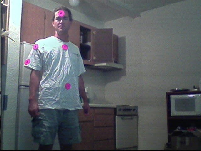
Previous experience showed the classic international pink was the best chroma keying material & a doughnut was the easiest shape for current cameras to isolate. When chroma keying is combined with a unique shape, it gives 2 layers of redundancy.

A 4k camera detecting a full body, international pink, digital camouflage suit would be ideal.

marker01.jpg


Next would be digital camouflage markers, but given the reality of only having enough money for 640x480, we have only

marker02.png


Where to place the markers so a single camera can detect range is the next problem.

crock.jpg

MOCAP-1.jpg

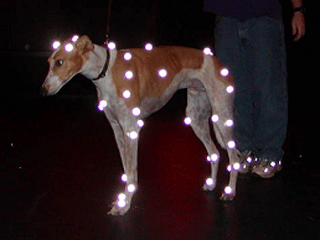
steve_markered.gif


It's become quite clear that retroreflective marker is the new fashion statement. There are ongoing, unreliable attempts to automatically isolate a human body from an image, but making the world easy for robots to navigate, rather than making the robots better at navigating the world is the theme. The markers are going to become normal attire before the autonomous camera works. 


It was finally time to use some of the electronic bits from years ago.

rx5808.jpg

There's a 5.8Ghz receiver labeled rx5808. It needs 3.5-5.5V. A channel pin is grounded to select the channel.


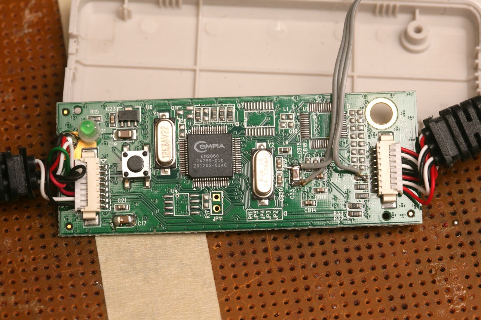
usb01.jpg


A USB capture board is wired to power the receiver with 3.3V.

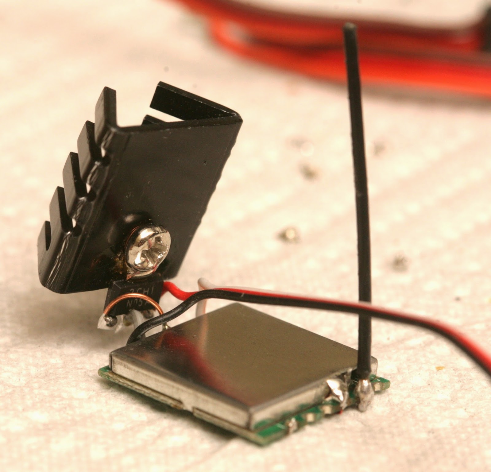
tx5823.jpg


There's a 5.8Ghz transmitter labeled tx5823. The same transmitter was sold by many hobby shops with different voltage limits. They all accept 3.3V, though some accept 5V. A channel pin is grounded to select the channel. It needs 400mA & heats to 55C.

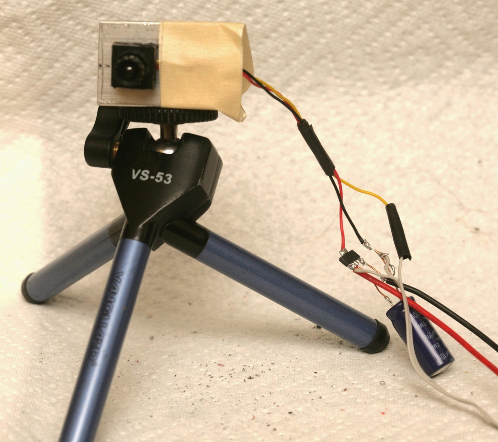
cam01.jpg


There are 2 cameras which need 5V. It took a lot of voltage regulators to finally get the 5.8Ghz system running.

composite.jpg


Direct composite video.

rf.jpg


5.8Ghz video. Would actually say there's no difference in quality.

markers01.jpg


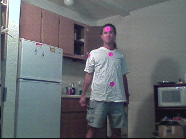
It's finally time to try some markers + low definition 5.8Ghz. Being interlaced requires the resolution to drop down to 720x240.

markers02.jpg


Barely any detail is visible.

markers03.jpg


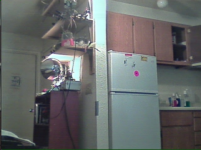
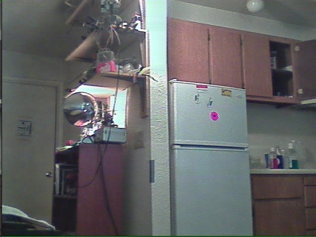
Motion blur wipes out the detail while retaining only color. It was a disappointing result, but it shows how the age of HD video has erased our memories of how bad NTSC was. 1920x1080 is minimum with 4096x2048 the ideal resolution.


The ground station needs to record the video as well as scan it for position. The only spare part is a laptop. Since the follow cam's mane mission would be capturing running, the need to carry a laptop has been the showstopper.


For portable computing, the long reigning Odroid is dead. You need to be buying the Minnow Max. Unlike the boat, the Minnow has a dual core 1.3Ghz x86_64. It should be far ahead of the quad core ARMs. Personally have gotten nothing but grief from quad core ARMs.



Read more…

af55bbb2d9ccafd489c65a89cede0eab_large.png?1405481899

Check this out if you're interested in adding thermal capability to your drone. The resolution is lower than FLIR, but the accuracy of the readings seem to be very high (0.2*F). From the Kickstarter Specs Section:

Product Specs:

  • 64x62 thermopile array with integrated optics. 
  • Best sensor resolution at this price at 0.61 degree angular resolution
  • No non-uniformity correction needed with thermopile technology 
  • Frame rate up to the ITAR-TASS regulations limit of 9 frames per second to any fully Bluetooth- or WiFi-capable device. 
  • Low power consumption and 850 mAhr battery provides up to 8 hours of continuous use without charging, or over a month if just using for 10 minutes daily. 
  • Android application for smartphone or tablet 
  • iOS application for iPhone and iPad 
  • Python & OpenCV application for windows & linux desktop 
  • App or button-driven laser pointer and online temperature display aligned to center of field of view with 0.2 deg Fahrenheit accuracy
  • Thermal measurement range: -50F to 450F 
Read more…

APM Telemetry using an Android Smartphone

3689609712?profile=original

A big enabler for UAVs going forward, especially with respect to commercialization, will be improving telemetry range. On that note, I've released my MAV Downlink Android application and associated tools today.

MAV Downlink opens up a new communication pathway for you to talk to your UAV while it is on a mission. This pathway uses an on-board Android smartphone to push MAVLink communications onto the Internet, then adds an intermediate server that hosts these communications and binds them to interested Mission Planner applications.

3689609641?profile=original

Pictured above is the general gist of the application.

I have been using it for the last few months to be able to communicate with my Sky Hunter in flight at essentially any range as long as I am at a field with good cellular service.

I know this idea isn't totally unique as there are several guides on how to enable UAV telemetry using cellular modems. To my knowledge, though, this is the first application that enables you to accomplish this easily using an old Android smartphone you probably have laying around. The big gotcha is that the smartphone must have an OTG compatible USB port. Fortunately, there are many cheap phones with these, notably the Galaxy Nexus:
http://www.ebay.com/sch/i.html?_from=R40&_trksid=p2050601.m570.l1313.TR0.TRC0.H0.Xgalaxy+nexu&_nkw=galaxy+nexus&_sacat=0

Right now, this application requires you to run your own dedicated server to host communication between the onboard smartphone and your MAV mission planning application. It also sends MAV commands in the clear with no authentication or encryption over public wireless airwaves. As such it is only really useful for hobbyists with good knowledge of networking.

It has also been brought to my attention that the Pixhawk cannot be connected to a standard Android phone via OTG. You may be able to put together a custom powered hub that connects to the Android phone but I cannot make any gaurantees. This has been tested on APM 2.6 and 2.5 boards.

I would like to develop this application further by adding dedicated servers so that virtually no set-up is required on the end-user's side. This would also enable me to add authentication and encryption to the communications channel so people using this do not risk their UAV being hacked.. no matter how unlikely that might be.

However, it works fine for me right now. Before I put any effort or money into improving it, I wanted to gauge public interest in it. Please let me know if something like this interests you by dropping a comment below.

You can try the application now. Here is a link to the Android application:
https://play.google.com/store/apps/details?id=com.appliedanalog.uav.mavdownlink
And the users manual:
http://www.applieduas.com/mav_downlink_advanced_manual.pdf

Read more…

EasyWing FPV flying wing

3689609196?profile=originalHi, let me introduce my new FPV flying wing, the modded EasyWing.

The original EasyWing was designed by JAN-CHE in Hungary (link to JCP webshop), also he has been cutted all the EPP parts for me. Many thanks on his support!!!

So I decided to design a new center part, I started the design in 3D (as I use to do...). First I used vertical fins at the wing ends (like in original EasyWing), but later seemed to be a bit unstable in yaw direction. So I replaced them closer to the center line, and they are facing outward by 1-1 degree (like in the Funjet). To avoid high level of turbulence at the wing tips, I designed small winglets too. They are working great. Here is the final 3D model, before building. Quite similar, isn't it?

3689609323?profile=originalMy goal was to build a small-enough plane for FPV purposes, and make it as efficient as it can be. All wooden parts are laser-cutted. To avoid damages at the wing front edge, I covered them with 80g glass-fiber sheet (used pvc vinyl for shiny surface finish):

3689609266?profile=original 3689609350?profile=original

3689609391?profile=original

 3689609212?profile=original

Here is the complete parts list:

  • APM 2.6 autopilot + airspeed sensor + battery monitor + MinimOSD + Crius CN-06 GPS
  • FrSky TFR-4 FASST compatible receiver in PPM mode
  • 720 TVL 30x30 panel camera
  • 720p keychain camera (W/O housing)
  • immersion 600mW 5.8 GHz video TX
  • Turnigy TGY-113MG wing servos
  • Hitec HS-5065 servo on camera moving
  • 3DR 868 MHz telemetry module
  • Turnigy SK3 2826 1240KV motor + Graupner 8x6 folding prop + 18A ESC
  • 2200 mA 3S Turnigy A-SPEC

More technical datas:

  • AUW: 860 g
  • Wingspan: 1050 mm without winglets, 1170 mm with winglets
  • Total flight time: 20-25 min
  • most efficient: 45-50 km/h (4-5A total current)
  • max. speed: 70km/h (limited by ArduPlane)
  • stall speed: around 35 km/h

Here is a small test-flight video. (keychain camera's lens still needs to be fine adjusted, so the colors…)

Best regards

Adrian

ps.: Some more details:

3689609399?profile=original 3689609416?profile=original

3689609237?profile=original3689609287?profile=original

3689609462?profile=original

3689609246?profile=original   

Read more…

3689609141?profile=original

Pictured above is a twin tail boom Pusher Composite UAV made by Paramount Advanced Technologies. It was fitted with our autopilot and flight control software and we spent a few weeks flight tuning the system and implementing full auto takeoff and auto landing modes.

About 4m wingspan, pusher prop, 4 flaps, split elevator, flies like a dream!

These two modes used the Lightware SF10 Laser Rangfinder as the source of height above ground for the Wheels up detection, and for the landing approach and landing flare modes. Still a little work in getting touchdown closer to the target point - but landings are smooth and safe..

The SF10 performs flawlessly, giving cm accurate height data from 60meters AGL and has enabled the auotlanding function to be easily implemented.  This airrcaft in its test guise weighs 25kg, with electric motor drive. For those interested in more info on the UAV, contact Paramount Advanced Tech. in South Africa - they are on the web..

Here are two videos of the landing, approach and touchdown. You will notice that the UAV approaches the landing strip, and flies on a ways if the touchdown would have been short, and then does finals with the flare and a smooth touchdown.

Nice and Slick!

The videos are low res - takes too long to download for viewing here in Darkest Africa!

http://youtu.be/aV8eXD8_MuA

http://youtu.be/SHmpS1vexVM

Thanks Laserman for the SF10! ( see www.lightware.co.za)

The Nampilot

Read more…

Mini Talon FPV Plane

The Mini Talon FPV V-tail Drone is the new little brother of the popular Talon FPV plane. The all EPO moulded airframe  comes in kit form and due to its smaller size is great for packing with you on your favorite FPV gear. The kit comes un-assembled with EPO and laser cut plywood parts. A spare camera nose bubble is included should you damage your Talon. Also notice the nose wheel for smooth landings on tarmac and protection of the bottom of the Talon.

The video clearly shows the massive amount of space for your FPV gear. The wing breaks down in 2 pieces, connected with carbon fiber rods. The center piece of the wing can be removed for easy access to your gear. 

Specifications:

Wingspan: 1300mm
Length: 830mm
Flying Weight: 1000~2000g
Wing Area: 30 sq. dm.

Required to complete the kit:
4+ Channel Transmitter and Receiver w/ V-tail mixing
4S 14.8V 5000-10000mAh LiPoly Battery
4 x 9g Servos
2814 1000KV Brushless Motor
40A Brushless Speed Control
9x4.5 propeller

The mini Talon is available from Hobbyking for US$ 81.89 (or less, depending on your membership level)

Read more…
3D Robotics

3689609132?profile=original

From the BBC:

When it comes to flight, nature just has the edge on engineers.

This is according to a study comparing hummingbirds with one of the world's most advanced micro-helicopters.

Researchers found that - in terms of the power they require to lift their weight - the best hummingbird was over 20% more efficient than the helicopter.

The "average Joe" hummingbird, however, was on par with the helicopter, showing "how far flight engineering has come".

The findings are published in the Royal Society journal Interface.

Lead researcher Prof David Lentink, from Stanford University in California, explained that the flight performance of a hummingbird - the only bird capable of sustained hovering - was extremely difficult to measure.

"Imagine a 4g bird," he said. "The forces they generate are tiny.

Flapping and flying

Moth in flight (c) SPL

As birds and insects move through the air, their wings are held at a slight angle, which deflects the air downward.

This deflection means the air flows faster over the wing than underneath, causing air pressure to build up beneath the wings, while the pressure above the wings is reduced. It is this difference in pressure that produces lift.

Flapping creates an additional forward and upward force known as thrust, which counteracts the insect's weight and the "drag" of air resistance.

The downstroke or the flap is also called the "power stroke", as it provides the majority of the thrust. During this, the wing is angled downwards even more steeply.

You can imagine this stroke as a very brief downward dive through the air - it momentarily uses the creature's own weight in order to move forwards. But because the wings continue to generate lift, the creature remains airborne.

In each upstroke, the wing is slightly folded inwards to reduce resistance.

"As a result the drag of a hummingbird wing has never been measured accurately."

Drag is the force opposing the upward force of lift that birds' wings generate by flapping.

Prof Lentink and his team wanted to understand if feathered hummingbird wings were more efficient - using less power to overcome drag - than the engineered blades of a helicopter of a similarly tiny scale.

He and his colleagues compared the birds' performance to an advanced micro-drone called the Black Hornet - a 16g helicopter used for surveillance by British troops in Afghanistan.

To make the laboratory measurements, they used wings from hummingbird specimens kept in museums.

By putting these detached wings into an apparatus called a wing spinner, the team was able to measure exactly how much flapping power was required to lift the bird's weight.

Prof Lentink's colleagues at the University of British Columbia in Canada also made recordings of wild hummingbirds in flight, to measure the exact movement of their wings - which beat up to 80 times per second.

"By combining the wings' motion with the drag [that we measured in the lab], we were able to calculate the aerodynamic power hummingbird muscles need to provide to sustain hover," explained Prof Lentink.

One species - the Anna's hummingbird - was champion hoverer, performing much more efficiently than the helicopter.

But on average, the birds hovering performance was "on par with the helicopter".

"This shows that if we design the wings well, we can build drones that hover as efficiently, if not more efficiently, as hummingbirds," said Prof Lentink.

"Clearly we are not even close to hummingbirds in many other design metrics, such as wind gust tolerance, visual flight control through clutter, to name a few.

Dr Mirko Kovac from Imperial College explains how drones whose design is inspired by nature are set to become part of our everyday lives

"But if we focus on aerodynamic efficiency, we are closer than we perhaps ever imagined possible."

Dr Mirko Kovac from the aerial robotics lab at Imperial College London said the study was a great example of research at the interface of biology and engineering.

"Studying hummingbird wing shapes can not only give insights into the biomechanics of animals," he told BBC News, "but the gained insights can also be used to build the next generation of flying micro robots.

Read more…
3D Robotics

3689609023?profile=originalGood news, I think. Last week the FAA issued a National Policy Notice (N8900.268) to its field inspectors, directing them to counsel and educate UAV operators before considering whether to take enforcement action.   It is just three pages, with attachments.   My take on this is that the FAA has taken a beating in the media and among the public in trying to shut down small UAV operators, whether it is search and rescue, beer delivery, filming a wedding, or other very low risk operations, and this is an effort to moderate that.

So, consistent with what the agency regularly assures the public – the FAA’s interest is in compliance, not enforcement (although enforcement is one or several means to achieve compliance) – this guidance instructs inspectors first to counsel the operator, and if warranted, send an “informational letter.”  Enforcement action should be reserved for operators who are “uncooperative or intentionally noncompliant” or where an operation “poses medium to high risk” to the National Airspace System (NAS), and even in such a situation, the FAA should consider whether a warning letter or letter of correction instead of a civil penalty is appropriate. (An “intentionally noncompliant” operator is one who commits repeat or intentional violations.)

Read more…

raspiHUD - Ground based HUD without FPV

3689608971?profile=originalBeing able to see what the autopilot is thinking in real time is a valuable tool for tuning autopilot behaviour.  FPV is normally used for this but I can't use it on my aircraft.  A good solution is to use minimOSD on the ground driving a video monitor.  I have had a few flights with this and it works very nicely.  minimOSD is amazing but still limited in what it can do.

The raspberry pi is very cheap, has a composite output and a good graphics accelerator.  I need the composite video for the pirate eye monocle I use. Using a laptop and HDMI->composite converter is not reliable and very poor quality.  To get a reasonable frame rate (~20fps) the openGL ES2 3d graphics capability of RPi needs enabling.  The amazing pi3d python library was the obvious choice.  It will also run on an x86 linux machine running x so development time is quick.

There has been a bit of optimising to get reasonable performance.  The resulting python module is a functional proof of concept but it is a way from finished.  At 20fps it consumes 70% of the processor time.  That leaves plenty of capacity for drawing all of the status items and some capacity for drawing more 3d objects.

I do have my own plans to add to the raspiHUD.  What would you put on the display?  Proximity warnings with 3d position?  Ground elevation map?  Local weather conditions?

With some advanced fiddling RPi might be encouraged to put its camera output on the background, then it would become a proper (but large and heavy) in flight FPV HUD.  I don't plan to do this myself.

More raspiHUD details and documentation available here (LINK FIXED)

Learn more about pi3d here

paya tech video monocles

The pirateeye monocle from paya technology.  HUD flying without the need for a buddy.

3689609004?profile=originalps. if anyone else thinks my hud design looks like it is smiling face then you are not alone.

Read more…
3D Robotics

This a gorgeous aircraft and the autonomous flight and image processing to detect "Outback Joe" is already working, as you'll see at 2:34. 

Here's more about the Swiss Fang team:

This is the website of Team Swiss Fang, the swiss competition entry to the 2014 UAV Outback Challenge. We are developing a state-of-the-art autonomous, long range Search and Rescue UAV.

Drones for Search and Rescue

We are with our partners part of the revolution in the skies, bringing unmanned airplanes into real applications. In the area of Search and Rescue drones can help saving lives. The Australian Outback Search and Rescue challenge is an ideal scenario to demonstrate the performance of our platform.

Technology

We have an unique approach, combining a very efficient flying wing airframe with the newest battery technology for maximum range. Our autopilot design performs fully automatic flight and landing. The fully automatic computer vision based lost person detection allows the plane to find lost hikers or other missing people on the ground.

Impact

The autopilot developed by members of our team is available as open hardware and the first open hardware autopilot produced in series meeting the CASA safety regulations for the competition. We are not just creating a novel search and rescue plane, but bring the technology to a level where it can be immediately applied in real scenarios and at larger scales.

Team

Our team consists of a number of the PX4 Autopilot Project core developers, allowing us to not just customize the autopilot for the competition task, but to actually design it for it.

Swiss Made

Our team is based in the Zurich Area, called „the silicon valley of robotics“. We have strong ties to ETH Zurich, one of the world leading universities in aerial robotics.
Read more…

40" RC Manta Ray

3689608817?profile=original

"Looking for Feed Back from all of you" (Thanks in advance)

Commercial Grade Design (40" Manta-ray Series)
Custom Design and Manufacture of UAV to suite application
Videography/Cinematography

40" Manta-Ray Spec.

Frame only $600.00
rtf custom build to suit your application approx. starting cost $4000. depending on requirements


-100% Aluminum Frame
-Different Motor sizes available
-3 sizes for props. available
-many different mounting points for payloads & Equipment

www.rcmantaray.com

Read more…

3689608744?profile=original

- UPDATE -

After some minor updates and changes, I started my Indiegogo campaign.

Regards, Adrian

- UPDATE -

Hi, it's me again from Hungary. Let me show my next design, a 480 sizde heli built for FPV and aerial shooting.

First of all, let me tell the origin of my idea. I saw a video from 2012 about a 480 size T-rex sport, with 32 minutes of flight time!!! Although he used 8000 mA with ~1500g AUW, I think with the same weight and about 6000mA battery 20 minutes could be reached.

So I started to design a custom heli based on T-rex 450 PRO parts, pixhawk controller and Mobius HD camera with 3-axis gimbal. Since vibration is quite a big problem of helis, I separated the frame into two main parts and connected them with rubber dampers. I hope high amplitude low frequency vibrations can be eliminated from the lower frame part:

3689608671?profile=original

3689608684?profile=original

To avoid vibrations from tail drive, I decided to use Direct Tail Drive instead of belt or shaft (thanks to Robert Lefebvre's idea), I found a suitable Hacker motor.

3689608775?profile=originalFor materials I'd like to use 1,5 mm G10 for frame parts, 2,0 mm G10 for gimbal holder plate and 2,5 mm G10 sheet for battery tray. Gimbal parts will be 3D printed. Aluminium parts will be CNC machined.

Now the 3D model and the part designs are ~90% ready, for further optimisation on parts I will need the electrical components, motors, rotor parts, etc. to colledt dimension datas andexact weights. Now this modell takes ~1550 g of AUW, I think 50-60 g could be saved with parts optimization. Solidworks can also calculate the CG, now it looks like it is OK. But CG will be tuneable with battery position too.

Since this heli will take a lot of money, I'm looking for sponsors because I don't have enough spare money to build this project. If can offer the complete 3D solidworks model and 2D drawing of all custom parts for producing of course. (BTW I don't want to sell this heli as a kit or in any other way, I don't have enough time and energy to give support for customers, produce parts, etc. I can't quarantee the success, but at least I hope... :) )

So if you like my design and  would donate me you can do it by Paypal or you can send me any of the missing parts instead. Just connect me by e-mail (nhadrian @ gmail.com) for further informations.

Here is a continously updated parts list. The red colour shows that the part is still missing, the green means I already have it. Further renders and pictures will be shared in this folder continously.

Many thanks in advance.

Best regards

Adrian

Read more…

Hello Diy Drones Universe,

This is Joshua Johnson here to discuss CAD Drones, LLC's long term project that will be the heart and soul of our Drone company that began a little over 5 months ago!  Right away we saw the potential in Cloud Computing related to the storage and Open Source collaboration of CAD Files and Autopilot Code related to Drones.  The future of Drones rests on the shoulders of 3D Printing and CAD Software.  We are working behind the scenes with many different companies mentioned in the video above to create a tool and resource out of CADDrones.com that will be an amazing resource for everybody in every level of expertise in the drone market/industry!  We truly believe that before startup companies move their Drone Products onto highly successful platforms such as Kickstarter, CAD Drones will be the place that most of these companies will get their product Open Sourced Developed, find members for Dev Team's, and much much more!

Over the next 24 Hours things on CADDrones.com will be changing and be reorganized for the next phase of our development.  We want everyone who wants to be a part of the CAD Drones Maker Movement to download the free hobbyist/enthusiest "Autodesk Fusion 360" Software and you will understand instantly why we chose that moving forward if you familiar with HTML.  If you are not during the update into phase 2 of our development we will be creating instructions on how "Fusion 360" will be used for Open Source collaborations on CADDrones.com!  When you are sharing your projects on CAD Drones we encourage everyone to add "Donation Buttons" from websites services like paypal so other CAD Drones members can donate to your Startup Drone Project if they enjoy your work and want to see you work your way up to building your own startup Drone Company.

Feel free to ask any questions you have about CAD Drones, LLC, our website, or even how we plan on building a tool/resource that will be one-of-a-kind in the Drone Industry!

Take it Easy DiyDrones.com,

Joshua Johnson

Read more…

A Simpler Option for Aerial Imagery

3689608576?profile=original

Hello. As a long time lurker here, I'd like to share my latest project with the DIY Drones community.

In working with orthophoto generation from UAV imagery using the current crop of still-photo stitching based programs, I have found the process to be complicated and frustrating.

I thought there must be a simpler way, and it occurred to me that pushbroom scanning from video is another way to make nice orthophoto-like images. This works without going through the complex 3D reconstruction process that the expensive stitching programs are using.

I have created a program called Aeriality Video Pushbroom. It is simple, it is available now, and it is very low cost. You can find it at www.aeriality.io

What it does is take an aerial video like this:

And it creates a constant-perspective strip-map image like the one one the left.

Even though it is a simpler process than the 3D reconstruction based stitching, pushbroom scanning has some advantages in comparison.

  • Its much faster. Get results in minutes instead of hours.
  • It continues to work well where stitching often fails to find key points, such as over farm fields, bare soil, or water.
  • When stitching has problems you get holes, gaps, and out of place or highly distorted images. With Aeriality Video Pushbroom errors in a good image are limited to small localized distortions.
  • Allows simpler hardware, flight planning and operations. You don't have to worry about image overlap or shutter triggering. And post-flight you only need to work with a single video file instead of hundreds of still photos.
  • It runs locally on your machine. No need to wait to upload lots of large files to a cloud service, and no worries about the privacy or security of your data.
  • Very efficient for long surveys. You can summarize a video into to an output image faster than real time viewing of the video. Potential applications in surveying power lines, pipelines, fences, towers, agriculture, and search and rescue.


Also, with this software I am testing a theory of business, sales, and pricing, that people will pay a reasonable price for something if it creates value for them. I would prefer to make money only if you are getting value from my work. In fact, I want to create more value for you than I capture.

With that in mind, I made Video Pushbroom with individual $3 licenses that can be used for each single video you want to process (only verifying its cryptographic hash against our server). And if you like the software and find that you are using it a whole lot, or want to use it without an internet connection to our server, there is an unlimited use license that covers you as well. To make it fair, if you ever want to upgrade to the unlimited license, the price of any single uses you have purchased will be deducted from the unlimited price. At the current pricing, that means if Aeriality Video Pushbroom is so useful to you that you have used it 33 times, you can keep using the software for free after that.

This being the internet, I realize that some people like to tear things down. So I thought I would pre-respond (prespond?) to some potential criticisms:

This doesn't actually do any alignment of the pushbroom scan, aren't you aware of all of the work that does this? Photogrammetry is a hard problem and you are not even trying to solve it. This sucks and is not as good as X.

Yes, I am aware of that (clearly, since I'm attacking my own straw-man here). The software will get better and add more features, though with a priority on simplicity. I am aware of the research literature and common techniques used by the computer vision, photogrammetry, and remote sensing communities, and have an advanced background in those fields. I hope that people will find the current software useful as-is, so I am releasing it for sale now (and not selling a dream on Kickstarter).


Thanks for reading. I hope you try my software, www.aeriality.io

thanks
-Taylor

Edit: The original strip map got cut off in the post. A full version is below

3689608589?profile=original

Read more…