This is a heading hold test for the ArduPilotMega based (ArduBoat) sailboat autopilot. The boat is sailed manually on a reach and then heads downwind holding a heading of 0 degrees and performs a jibe.We have waypoint guidance working in hardware-in-the-loop, so we expect to do waypoint testing soon. We might have to figure out a better solution for our digital wind vane as the potentiometer from radio-shack is too sticky to detect light winds well. The digital weather station from sparkfun might be a good option.
All Posts (11086)
Sort by
I've done some more work on the stability code in my Propeller-based quadrotor and gotten significantly better flight performance. It still needs some tuning, but all my oscillation problems are gone.
In the office:
Walking around outside the office:
After some delays in sourcing components and setting up a good test procedure, we now have the PhoneDrone Android/RC interface board in production and available for purchase ($99).
If you've been wanting to experiment with connecting Android phones or tablets to the world of RC vehicles, this is the board for you. It's the only Android ADK board on the market designed to work with RC equipment, and it can interface with APM (1 or 2) via serial, too.
From the product listing:
"The board has 8 channels of RC in and out, with PWM-to-PPM conversion and multiplexing between RC and Android control. You just plug the Android's phone USB connector into the board and you have two-way communications with RC gear and any other board, such as APM.
That means that you can switch between RC control and Android control or mix the two. An example would be "fly/drive by wire". You steer your vehicle via RC, but an Android phone does the actual control using its onboard IMU. On a car, that would allow every turn to be a high-speed controlled drift, for instance (we may show something like that at Maker Faire).
Or, with a UAV, you might have the Android phone doing high-level image processing and object tracking, sending mission commands to an autopilot board such as APM. You might also want to use the phone's long-distance wireless instead of an Xbee for two-way telemetry.
This can either replace APM if you've got equivalent code running on Android, or compliment it with the Android device doing image processing or long-distance wireless comms.
SPECIFICATIONS:
- 8 Input&output PWMs
- Native USB host master (MAX3421)
- Native USB slave (Atmega32-au)
- Arduino Compatible
- Atmega2560 as main controller
- Atmega32-u2 as FTDI substitute and PPM encoder
- Three spare serial ports to communicate with other boards (including APM)
- Build-in 5V-2A switched power regulator (input range 6V - 36V)
- Build-in 3.3V LDO power regulator
- Android TM compatible...
- All Atmega2560 pins exposed.
- High quality PCB is ROHS/lead free, Gold immersed.
- Dimensions: 4" x 1.6"...
Just got my DX8 + a second receiver for free!
Iv read more TX/RX reviews than I can stand and finally settle for this combo.
I have to admit its alot better than my turnigy 9x. Thank God for rechargeable batteries and no #%$#$ beeping!!!
The features are great and the telemetry for me was the biggest deciding factor.
Dont get me wrong, I trust the voltage monitor on the Ardupilot, I just wanted something stand alone that could tell me the voltage level and temp of my batteries. All things considered im going to be up in the air for 20+ mins per flight.
Also it has a nice throttle cut feature, where if the throttle drops below a specified level, you can set it to automatically switch to a pre defined mode, eg RTL! Hence, if I loose TX signal or the copter flies out of range of the TX. It should automatically RTL. This can also be setup on the APM firmware. Always a good idea to have double backup!
I like to be safe. Be prepared for everything, or as much as possible!
Theres no kill like over kill. ;)
Pretty amazing, a package sent from China via DHL on Monday.
Arrived this morning.
After unpacking and reading the not too good english manual, but much better than most.
I attached it to my Nikon. Simple, straight forward.
Iv attached a couple of geo-tagged images with the addition of compass bearing!
On the way to my field theres a san-pedro cactus outside our front gate. With an unusual amount of flowers on it.
That is the 1st pic, the 2nd is the field and the 3rd was the same cactus on my way back. Half an hour and half a million bees later. I couldnt get closer without getting stung...
The only slight problem I might have is I have to use the electronic shutter control on the nikon for triggering with that ppm relay board from DIYD. Problem is that the GPS cable and shutter cable are the same damn cable.
So I either need to get a Y splitter or I have to carefully splice in a 3 wire cable for the shutter control...
G:)
Spent a lot of time trying to low noise overclock audio preamps. The main factor affecting you as you get an extremely high gain transducer into subterranian levels of noise is the power supply. Every consumer gadget encounters some humming noise before it encounters thermal noise. Even a DSLR has banding noise from a power supply ripple.
Power supply banding noise on an obsolete EOS 5D.
You would't believe how sensitive a primary microphone stage is to power supply noise. Merely toggling a pin on a microcontroller or driving an LCD panel would cause enough ripple in the power supply to generate a hum. 2 hums of different frequency would mix & create a harmonic within human hearing.
The whole affair made us wonder if our obsolete sensors couldn't be improved with more power supply filtering. Everything that makes money has loads of decoupling caps near each sensor, but we always flew with 1 cap for the entire autopilot & just the reference design caps for the sensors.
EEVBLOG's video on RC filters for smoothing PWM inspired us to look more at the subject. More importantly, he showed a dual cascaded RC filter squashing the ripple more than anything else, which conflicted with our tradition of using the fewest components. So we applied some RC filters to the king of noise: the SCP 1000.
It's an obsolete barometer, but it's all we can afford. Tried 10ohm + 480uF, dual 10 ohm + 480uF, & 100ohm + 480uF.
The curves reflect the board cooling after soldering. The noise decreased dramatically with the RC filter & is now in the 1/2 meter range. The reference design obviously left a lot to be desired & a lot of noise is coming from the microcontroller itself.
The 100ohm + 480uF did slightly better than the dual 10 ohm. So in matters of cost & weight, you're probably still better off leaving the dual cascaded RC filter at home.
Our obsolete GPS module wouldn't work at all with an RC power filter. That has transients at too low a frequency to dampen out without an active regulator. The barometer most certainly has its own transients, but still benefitted.
The gyros didn't benefit at all. They're probably frequency dependant. Left the cap on, to dampen vibration.
Maybe the transient voltages of polling a radio receiver can reduce its sensitivity? Maybe using the interrupt pin on our 900Mhz radios would increase their sensitivity, but as soon as the 1st byte of data came in, the device would lose sensitivity for the rest of the packet, as we clocked out the data. Maybe if we used the analog pin as a raw UART instead of the digital FIFO, it would be more sensitive.
Remarkable that 2 years later, radios haven't gone anywhere in terms of capability or parts. There's been no major effort to go outside the 2.4Ghz band.
To our amazement, Ning now limits blog posts to 7 photos, so the rest are on blogger. Everyone's cutting back on the freebees & firing everyone as the stock market booms.


Vika 1 flew again, after 1 year. Her adhesive tape had settled with the propellers facing forward after all that time. Round carbon fiber is unbreakable but impossible to build with. The RC filter got the altitude much more stable, but heading without a magnetometer was worse than we remember.
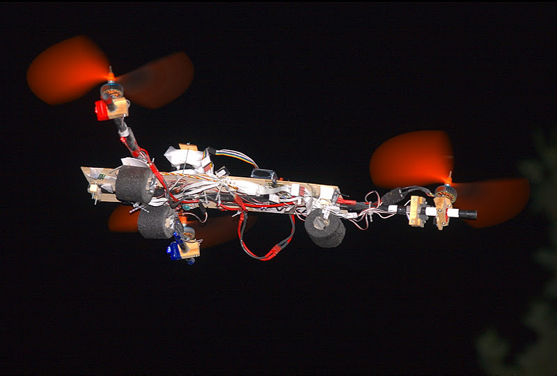


Someone gave us an AKM8973 almost a year ago. The datasheet seemed to have some errors in the pinout & it never did work.
Being a chronically unemployed programmer doesn't allow us to fly very often or buy the latest autopilot instead of hacking on the ghetto autopilot. Actually pursued the LA aerospace idea for a year, but never got any interest. The big thing these days for making money is making web applications with Ruby on Rails, but our analysis says it won't last any longer than J2EE.
Recently the Chinese ESC design utilizing the ATMEGA which we have been flashing with Bernard Konze's firmware has been disappearing from the market. This was the push I needed to finally decide to design and build a replacement. Collaborating with a friend, we worked on it over the summer. It is finished and I think it came out pretty well. I call it ESC32:
Design goals:
- Extremely fast implementation of requested throttle setting
- Ability to take high rate input
- Multiple input protocols
- Ease of programming, real-time debugging
- Efficient
- Inexpensive
The final specifications read:
- STM32F103 72Mhz MCU - 32bit ARM
- Firmware written in straight C
- SWD connector for real-time debugging
- Input via PWM IN / UART / I2C
- 1KHz PWM update rate capable
- All N-FET design with gate drivers
- At least 40A continuous with proper cooling, maybe much more
- 2S => 5S battery
- Option to power logic side via UART or PWM IN +5v
- Command Line Interface for testing / parameter modification / back channel
- 8KHz => 64KHz PWM out
- Current sensing / limiting
- Regenerative braking capable
- Closed loop control mode - experimental
- Lots of RAM and CPU cycles available for advanced control techniques
- BOM cost < $20 at quantity
* image courtesy of TC Pictures, LLC.
It is a drop-in replacement for the ESC's that I have been running with AutoQuad and will take standard PWM input up to 450Hz. I will eventually design new high rate PWM timing which will bring this rate up to 1KHz. It is a definite improvement over the ATMEGA design. Your flight controller can ask for large, quick changes in throttle and it is able to implement them very fast. This allows PID output to be tuned to be more aggressive and results in much smoother control.
Start ups are very smooth and I have not yet found a motor it could not start. It uses oversampling techniques which allow it to accurately control a BLDC motor down to 200RPM. Early indications based on some initial head to head testing with other ESC's show the it is very power efficient. This comes from the fast switching of the N-FETs due to the use of gate drivers. Less time is spent in the on-off / off-on transitions, so less power is used, less heat generated. No special heat sinks or cooling should be necessary for typical 10 to 20 amp usage. This also means that you can use higher PWM output rates without too much of a hit to efficiency.
* image courtesy of TC Pictures, LLC.
As the ESC is an extremely important component of multi-rotor UAV's, it is critical that it keeps running, no matter what. So you can imagine the amount of testing necessary before you can start to trust a new design with your expensive machine. There are a handful of people flying the ESC32 now and I myself have perhaps 10 hours without incident so far. There may still be problems, but I am fairly confident that it is trustworthy. It's all I fly now.
Have just finished ordering all the parts I need to build an aerial platform capable of carrying a Nikon D5100 SLR camera.
I have spec'ed up the power for some future heavy lifting projects.
The components are as follows:
---------------------------------------------------------------------------------------------------------------
FRAME: MikroKopter Okto XL + AltiStream: ventilated transparent dome
---------------------------------------------------------------------------------------------------------------
FC: Ardupilot V1.0 + MB1200 Sonar + Mediatek GPS + Magnetometer + Xbee Telemetry + Optical Flow Sensor
---------------------------------------------------------------------------------------------------------------
PDB: Photoshipone PDB
---------------------------------------------------------------------------------------------------------------
PROPS: EPP1245 CF (Chopped glass fibre)
---------------------------------------------------------------------------------------------------------------
MOTORS: Turnigy G10 Brushless Outrunner 810kv (.10 Glow)
---------------------------------------------------------------------------------------------------------------
ESCS: Turnigy dlux 55A SBEC Brushless Speed Controller
---------------------------------------------------------------------------------------------------------------
LIPO: Turnigy nano-tech 5000mah 4S 35~70C Lipo Pack
---------------------------------------------------------------------------------------------------------------
CAMERA: Nikon D5100 18-55+55-200VR
---------------------------------------------------------------------------------------------------------------
CAMERA MOUNT: Photoshipone mkTR
---------------------------------------------------------------------------------------------------------------
CAMERA MOUNT BEC: UBEC 5A
---------------------------------------------------------------------------------------------------------------
GPS GEO-TAGGER: Solmeta GPS Pro
---------------------------------------------------------------------------------------------------------------
TRANSMITTER: Spektrum DX8 with telemetry
---------------------------------------------------------------------------------------------------------------
FPV TX/RX: 5.8G High Power 200mW AV TX and RX Systems
---------------------------------------------------------------------------------------------------------------
FPV GOGGLES: Fat Shark Dominator 3rd Generation modular FPV System
---------------------------------------------------------------------------------------------------------------
As soon as I receive the parts, I will start a build blog...
G :)
As is customary and traditional, we celebrate every new 1,000 members here and share the traffic stats. This time it's a big one: 20,000!
We've been over a million page views a month all year. It just took us six weeks to get this latest 1,000 members--we're averaging about one new member per hour.
Thanks as always to all the community members who make this growth possible, and especially the moderators who approve membership applications and blog posts and otherwise answer questions and keep things ticking here. We've got about 40 moderators now, but if anyone would like to join this group, please PM me. If you've been here for a while and have been participating, you'll fit in great.
More fun from the supercool (and super expensive) motion tracking lab at ETH:
"Fast, safe transitions of multiple quadrocopters are often required in the Flying Machine Arena. In this video, we use an algorithm based on convex optimization to plan collision-free trajectories.
In the first part of the video, the destination points are selected ahead of time and collision-free trajectories are pre-computed. All the trajectories are stored before execution. In the second part of the video, however, the next set of destination points is picked at random while the vehicles are still en-route, demonstrating that the algorithm is fast enough to be used in real-time.
* Project by
Federico Augugliaro, Angela Schoellig and Raffaello D'Andrea
Institute for Dynamic Systems and Control, ETH Zurich, Switzerland
* Based on the work by
Yang Wang, Ekine Akuiyibo, Stephen Boyd
Information Systems Laboratory, Stanford University, USA
* Filmed at ETH Flying Machine Arena
http://www.FlyingMachineArena.org"
Quote from John F. Kennedy's launch of the Apollo Project. Picture of 3DR copters flying from today's 3D Robotics twitter feed.
Here's a look at the latest iteration of my Parallax Propeller based quadrotor. The current implementation uses an ITG-3200 3-axis gyro as the only stabilization sensor.
...and an outdoor flight:
This device is no match for an Randy's sensor, but it does (minimally) work. Think of this little project as a fun hack more than anything else. But with some tweaking and size reduction someone could probably implement an occasionally working altitude hold sensor for a fixed-wing RC aircraft.
This optical flow sensor uses CdS cells as light sensing elements. Recall that a CdS cell is basically a resistor whose value changes with illumination- more light results in less resistance. The fundamental sensing structure here is a pair of CdS cells connected in series to form a voltage divider. The middle node between the CdS cells forms the output. When both cells are equally illuminated, the output voltage is midway between Power and Ground (assuming the CdS cells are matched). If one cell is illuminated more than the other, the output voltage varies accordingly. An interesting quality of this CdS cell pair is that if you, say, double the amount of light striking both cells, the output changes very little.
Nine of these CdS cell pairs are laid out in a row, as shown in the video. Pay attention to the photo below to see how the CdS cells are placed and how they overlap within the array. The nine resulting outputs go to ports A0 through A8 (analog inputs 0 through 8) of an Arduino Mega. This project required a 'Mega because of the number of analog input signals.
For those of you with an image processing background, you can say that a CdS cell pair forms a simple analog edge detector, and that adjacent edge detectors are 120 degrees out of phase.
As light patterns travel across the CdS array, the nine analog signals will vary accordingly and can be interpreted by a basic one dimensional optical flow algorithm. For example, if a shadow moves left to right across the array, a pulse or step function will appear in sequence across ports A0 through A8 in sequence (or the other direction) which indicates visual motion.
To obtain an image, I just used a slit opening, which is a variation of a pinhole camera. This slit opening was oriented perpendicular to the CdS array, which preserves visual information parallel to the CdS array and smooths out information perpendicular to it. This helps make the array more sensitive to 1D visual motion in the desired direction. (For a rough metaphor, think of a bar code.)
I mounted all the electronics into a shoebox using masking tape. (For a more professional and durable version, use duct tape!) I also placed dark construction paper on the inside of the box to prevent light from bouncing around. I cut a slit opening in the box top as shown to be positioned over the CdS array.
The output can be read in two ways- The Arduino port D3 generates a PWM signal that, when connected to the RC network shown, can generate an analog output representing the optical flow (5V = max positive, 0V = max negative, 2.5V = zero). Alternatively you can read it out using the Arduino environment's Serial display.
The sensor is crude but does work. It needs a lot of light to function- it should work in a bright indoor environment but works better with natural outdoor lighting, say several hundred lux and up.
The Arduino sketch is attached here: CdS_OF_Sensor_r1.pde
Have fun!
Not sure if this is in the military category or not...
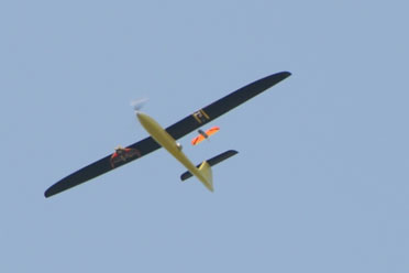
WASHINGTON, Dec 05, 2011 The Naval Research Laboratory Vehicle Research Section has successfully completed flight tests for the Autonomous Deployment Demonstration (ADD) program. The final demonstration took place Sept. 1 at the Yuma Proving Grounds, Yuma, Ariz., and consisted of a series of eight balloon-drops at altitudes of up to 57,000 ft, delivering sensor-emplacement Close-In Covert Autonomous Disposable Aircraft (CICADA) vehicles within 15 feet of their intended landing locations.
The ADD concept is to enable small unmanned air vehicles (UAV) equipped with sensor payloads to be launched from aircraft (manned or unmanned)
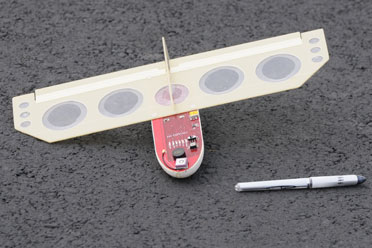
A custom autopilot for the CICADA, both hardware and software, was developed by the Vehicle Research Section to be both inexpensive and robust. The only flight sensors are a 5Hz GPS receiver and a two-axis gyroscope. Although
having minimal sensors, the navigation solution and the flight controller proved to be quite robust during in-flight testing, routinely recovering from tumbling launches. The flight controller also included a custom NRL algorithm that accurately estimated wind speed and magnitude, despite having no air data sensors onboard.
What happens when you put a bunch of roboticists and architects together in an empty art gallery?
This guy is reverse engineering the Neato Robotics Lidar system, which is by far the lowest-cost Lidar availalble. Neato has so far not made the Lidar available as a stand-alone product, thus this effort to clone and open source it.
A cheap and light Lidar system could open up a whole new class of UAVs that could navigate indoors and outside of GPS coverage. One way or another, it looks like that's on the way.
From the announcement:
The College of Journalism and Mass Communications at the University of Nebraska-Lincoln established the Drone Journalism Lab in November 2011 as part of a broad digital journalism and innovation strategy. Journalism is evolving rapidly, and journalism education must evolve with it, teaching new tools and storytelling strategies while remaining true to the core principles and ethics of journalism. The lab was started by Professor Matt Waite as a way to explore how drones could be used for reporting.
In the lab, students and faculty will build drone platforms, use them in the field and research the ethical, legal and regulatory issues involved in using pilotless aircraft to do journalism.
Journalists are increasingly faced with two problems: a growing appetite for unique online video in an environment of decreased budgets; and restricted or obstructed access to stories ranging from disaster coverage to Occupy Wall Street protests. The technology behind autonomous and remotely piloted vehicles is rapidly moving from military applications to the point where private citizens can own and operate their own drone. At the same time, high definition and 3D video cameras are getting smaller, cheaper and lighter. Paired with global position devices, they make ideal additions to an airborne platform.
In short, drones are an ideal platform for journalism.
Picture of a Gatewing X100 shown because the announcement randomly chose it as an example of platforms available. Once the students find out how much it costs, they may start looking for something cheaper ;-)
(Via The Verge)
I've seen that ArduPPM 0.9.87 has been downloaded about 2 hundred times.
It seems that we have no negative reports with this version.
This is a very good result and does confirm the good results we had at initial testing in the lab and through the development team.
I feel that we could now push this firmware to the realease 1.0 status.
If you have any decoding problems, please report it, so that i can include it as a note in the manual.
If you are happy with it, let us know as well. It will help to push it to 1.0 release.
There will be no modifications for the 1.0 release. We need rock solid massively tested code here because it is a very important link in the APM system.
ArduPPM binary is available in the Ardupilot-Mega Downloads section.
http://code.google.com/p/ardupilot-mega/downloads/list
More informations about ArduPPM here :
http://code.google.com/p/ardupilot-mega/wiki/Encoder?wl=en
If you don't know what is the ppm encoder, if you have no idea about how to program an AVR chip or if you have simply no need for it, then it's ok to keep your actual version.
Thanks, and happy flying.
This flight is took place before to open to the public.
Real demonstration has been done at football field of the university.
Randy and my self show off DIY Drones at Make: Fair at Tokyo on December 3 and 4.
We have very good feedback from visitors and exhibitors.
It will very good start of DIY Drones in Japan.
Everyone in the New York City area is invited to join me for a DIY Drones meetup at the Wired Store in Times Square at 6:00pm this Wednesday, Dec 7th. It's free, and we'll have free drinks, plus a cool DJ party starting at 7:30. I'll have the new APM 2.0 board to show and to play with.
We're calling it "Drinks and Drones". Alcohol and flying robots--what could possibly go wrong?
Come, bring your friends, or bring a drone for show and tell.
Just send your name and how many people you're coming with to rsvpstore@wired.com. Subject line: "Drinks and Drones"
