All Posts (14049)

Sort by

RTP [Robot Test Platform] (updated)

RTP%20-%20Frame%20assembly%20-%2011.JPG?width=600

 Me and a friend of mine are working on a new project which we want to share with other enthusiasts. It all started a couple of weeks ago when we wanted to do more with electronics, both the software as hardware side. We have been experimenting with Atmel AVR's for a while, and have quite an assortment of Arduino boards and extension modules. However, we never did anything more with this then some bench testing, up until now!

We decided to build a robotic test platform which will be suitable to test numerous electronic circuits and programs on. (thus the name RTP) It started with some plans for a small wooden platform and some transmission motors, but quickly got up scaled to something that could autonomous drive outside. Our plan is to equip the robot with sensors, cameras and a GPS receiver and be able to set up a traveling route with the computer, tablet or smartphone.

After some research on the standard hardware parts, motors, electronics and batteries we started designing the robot using SolidWorks. We came up with frame constructed out of sheet metal which will form the base of the robot. For the drive train our choice went out to two 500W 24V electric bike motors powered by six 12V 7Ah SLA batteries. To variate the speed of the motors we got our hands on two 36V 70A speed controllers, which are perfect for the project, because they support both a PWM input signal as a RS232 connection.

RTP%20-%203D%20Model%20-%20render%201.jpg?width=600


RTP%20-%203D%20Model%20-%20render%202.jpg?width=600

RTP%20-%203D%20Model%20-%20render%203.jpg?width=600

As you can see on the above images the design quickly took shape, and it started to look like a nice machine! A small story about the yellow wheels, we unintentionally found these at a local hardware store and immediately bought four of them. They where actually the first parts bought and the main reason the robot got this big.

Before we started building the real frame we wanted to check that we don't have any issue's with the drive train. We build a temporally test-setup providing the ability to test the motors, speed controllers and transmission. In the video below you see some footage of the first tests we did. It might look that one of the shafts is bend, but this was only a bearing which twisted in its housing due to the miss alignment of one of the gears. (fixed eventually!) After the tests we changed the positions of some gears, but nothing really spectacular.


 The next step was the actual building of the machine. Luckily we had access to a nice workshop with all the tools we needed. (laser cutting machine, press brake, lathe, mill and proper welding equipment) This made building an ease and we got most of the work done in a weekend.

RTP%20-%20Building%20the%20frame%20-%2002.jpg?width=600

RTP%20-%20Building%20the%20frame%20-%2003.jpg?width=600

RTP%20-%20Building%20the%20frame%20-%2004.jpg?width=600

RTP%20-%20Building%20the%20frame%20-%2009.jpg?width=600

After the frame assembly we test-fitted all the parts. This meant assembling the whole machine, and gave us the opportunity to drive around for the first time. As you can see the batteries and electronics where mounted on top of the machine as their position of their mounting brackets still needed to be determined.

All of the parts fitted perfect, and even more important, the robot drove pretty good! We took it completely apart and sandblasted most of the components. This didn't only remove most of the sharp edged and grinding marks, it also provided a good bare metal surface for the powder coating to stick to. We chose for a dark grey textured coating which came out awesome! We started assembling the robot and took the pictures shown below.

RTP%20-%20Frame%20assembly%20-%2001.JPG?width=600


RTP%20-%20Frame%20assembly%20-%2002.JPG?width=600


RTP%20-%20Frame%20assembly%20-%2004.JPG?width=600


RTP%20-%20Frame%20assembly%20-%2005.JPG?width=600


RTP%20-%20Frame%20assembly%20-%2008.JPG?width=600


RTP%20-%20Frame%20assembly%20-%2009.JPG?width=600

The final step was creating the bottom, top, front and rear panels to close of the internal parts and protect them from any dirt, sand and water. For these panels we chose a lighter grey which looks good next to the dark grey and yellow.

RTP%20-%20Frame%20assembly%20-%2010.JPG?width=600


RTP%20-%20Frame%20assembly%20-%2011.JPG?width=600


RTP%20-%20Frame%20assembly%20-%2012.JPG?width=600

The next post will cover the basics of the electronics and software that we are going to use in the RTP. But as we are still working on this an update might take a while. We hope you guys like our project and are interested in the progress.


More images can be found on: Robotic Test Platform - Gallery

More videos can be found on: Robotic Test Platform - Youtube

Updated on 02-01-2013: Fixed the missing videos.

Read more…
Distributor

Stackup Plates for Mounting Stuff

7915365_orig.jpg?width=200
3942251_orig.jpg?width=200

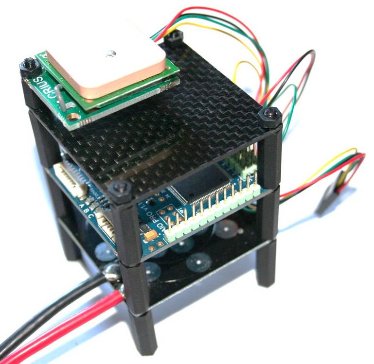
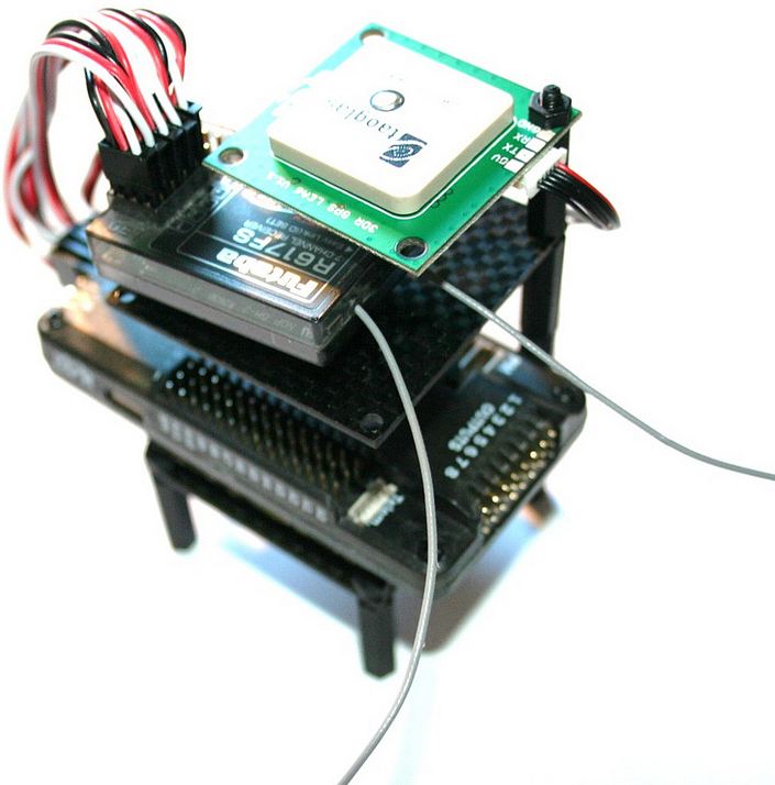
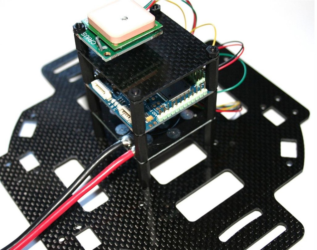
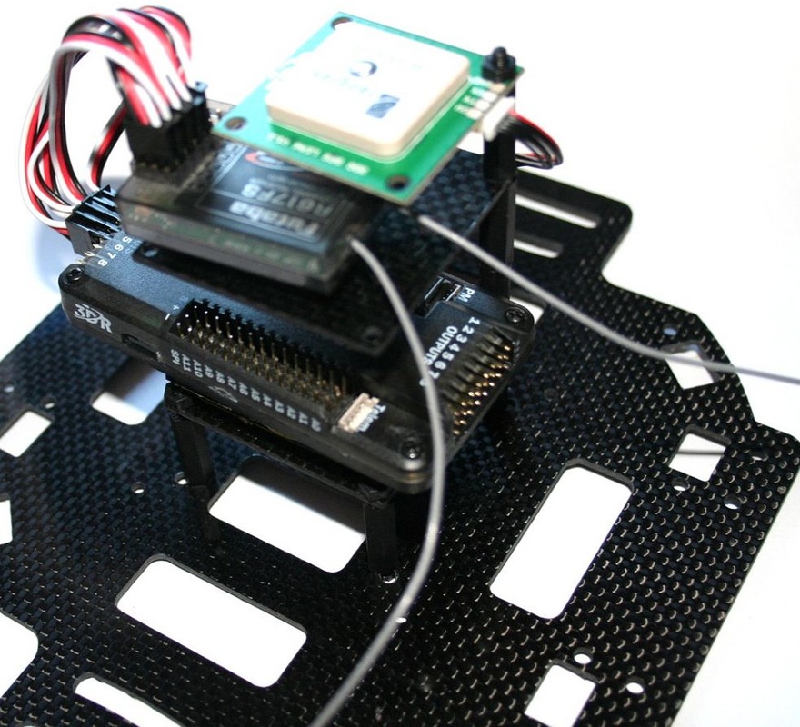
If you are looking for a nice way to mount all of your gear onto your multi rotor frame, you should have a look at our new stack up plates.  On the product listing you can choose what components you need so that you can create your own stackup.

7224921_orig.jpg?width=200If you are using AIOP or Multiwii boards with the same 5cm x 5cm footprint then you can also mount the included PDB on the stackup as shown.
You can also use some Vibration Dampers on the stackup for the flight controller.

4588888_orig.jpg?width=200If you are using an ArduPilot Mega 2.5+ board, then you can mount it as shown, you will also need to use some double sided tape to secure the board down.  This is a good idea because it also reduces the vibrations on the board so it will perform better.

Read more…

DroneCafe - Episode 7 - UAS - Telemetry

This is Episode 7 - UAS - Telemetry

DroneCafe - The Daily Cup

I hope you enjoy my video's and find them educational!  Check out the home of my Podcast on Diydrones.com or Click HERE!

Episode 6 - DIY Heli [05:44]

Episode 5 - Diydrones.com Live Assistance via Skype [03:28]

Episode 4 - Newbies Guide to Diydrones.com [12:34]

Episode 3 - DIY UAV [02:50]

***Please let me know if you have any suggestions or ideas for new episodes***

Read more…

Secrets of the MPU9150


mpu9150_06.jpg


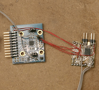
After another heroicly wasted day, the MPU9150 finally surrendered all 9 of its data streams. It has so many problems as a 1st run product, a much improved revision negating all of today's work is guaranteed. But with 2 MPU9150's lying around & a definite use, it was time to bang out a workaround just to get the data from it. The DMP firmware isn't going to happen.

Step 1: the 1st I2C command must be to set PWR_MGMT_1 (0x6b) to 0x01 to move it out of sleep mode & set the clock to the gyro oscillator. That puts 1.8V on the REG_OUT pin & 25V on the CPOUT pin. Nothing else works if it isn't the 1st command.

Step 2: set the remaining configuration registers after PWR_MGMT_1

0x37 = 0 // disable i2c passthrough
0x6a = 0 // disable i2c master
0x1b = 0 // gyro config
0x1c = 0 // accel config
0x19 = 0 // desired sample rate divider

The I2C passthrough didn't work. Only using dual I2C busses connected to the mane I2C & the aux I2C worked. The mane I2C reads the gyro & accel. The aux I2C reads the mag.

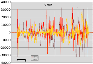
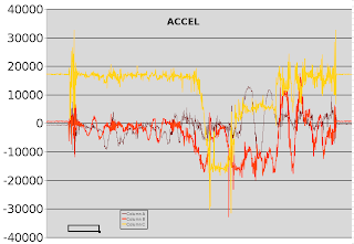
The real problem is if you simply read the gyro & accel registers, you'll always get the same value. They tried & failed to synchronize the register refreshes with inactivity on the I2C bus.

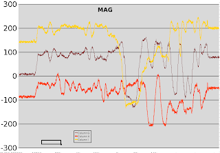
The only way to get the registers to refresh is to issue a bogus command to the mag on the mane I2C bus. I chose to read the mag status register (0x02) 1st on the mane bus to get the gyro/accel registers to refresh, then read the same mag register on the aux I2C bus to get the real value. It probably counts an unrecognized address as inactivity on the bus.

No amount of hacking could get the registers to update with passthrough enabled. It seemed to consider all communication with passthrough enabled as activity on the bus.

The aux I2C has decent enough pullups to read the mag at a decent rate. The mane I2C needs 1k pullups. It showed no obvious sensitivity to voltage changes between 2.5V & 3V. Its 1.8V regulator must make it immune to supply voltage fluctuations.


mpu9150_04.png

mpu9150_05.png

mpu9150_03.png

Hopefully that helps all the people with jobs involving the MPU9150 pay some of their medicare tax increases.


There's obviously some intended use involving the FIFOs, the myriad of slave registers, & the DMP instead of banging on the aux I2C manually, but any source code revealing how to do it is a closely guarded secret.  The Apple model of a basic & premium developer program seems to have caught on at Invensense.
Read more…

Video: How to fly in a sporting stadium


There have been many videos on how to crash and not how to conduct commercial operations.

The guys at Coptercam are setting the right example for all DIYers who are aspiring to become commercial UAV operators.  I have been watching the live cricket matches on Fox Sports and the Coptercam shots look fantastic.  The feedback from spectators seem pretty positive.

http://stuartrae.blogspot.com/2013/01/great-flying-at-cricket-foxcopter.html?spref=tw

Read more…

da5c15fb3e3544e06967c13ff402f77e.image.300x225.jpg

From Seeedstudio's site:

Time frame for pre-order: Jan. 31- Feb. 18, 2013
Time of shipping: April, 25, 2013
Ever wanted a development kit that flies? Well now you can! The Crazyflie is an open source nano quadcopter kit designed for flexible development and hacking. It's among the smallest in the world, weighing only 19 grams and measuring 9 cm motor to motor.
Features:
  • Small and lightweight, around 19g and about 90mm motor to motor
  • Flight time up to 7 minutes with standard 170mAh Li-Po battery
  • Standard micro-USB connector for charging which takes ~20min for the stock 170mAh Li-Po battery
  • On-board low-energy radio@1mW based on the nRF24L01+ chip. Up to 80m range (environment dependent) when using the Crazyradio USB dongle
  • Radio bootloader which enabled wireless update of the firmware 
  • Powerful 32 bit MCU: STM32F103CB @ 72 MHz (128kb flash, 20kb RAM)
  • 3-axis high-performance MEMs gyros with 3-axis accelerometer: Invensense MPU-6050
  • Available footprints to manually solder magnetometer HMC5883L/HMC5983 or/and barometer MS5611 (sensors not included)
  • Expansion header 2×10 pins 1.27mm (0.05”) pitch including power, I2C/UART, SPI/ADC. Header also contains ARM Cortex 10-pin JTAG (header not included)
  • 4-layer low noise PCB design with separate voltage regulators for digital and analog supply
Price is US$ 149
Read more…

3689500132?profile=original

The PX4 autopilot now supports the Graupner HoTT telemetry system bringing live flight data right to your transmitter’s display.

Real-time Flight Data on your Transmitter Display
The latest PX4 firmware now supports telemetry for all HoTT transmitters and receivers. With the current release you are able to view Lipo voltage, altitude (barometric) and onboard temperature so you can monitor your airframe status live without needing to look at your ground control station.

Work is currently underway on supporting current sensors as well a the addition of a range of GPS properties such as heading, altitude, satellite lock, satellite count, etc.

Setup Tutorial
Getting HoTT telemetry running with the PX4 is simple to setup. To make it easier for you we have put together a step-by-step tutorial video:

For more information, take a look at the HoTT Telemetry tutorial on the PX4 wiki.

Read more…

UxV control station - first video

This is just a short technology preview for the mission control part of my UxV Control Station project. It does already talk to the APM but besides decoding GPS data, it has no function yet. But development is going on.

Sorry about the focus... My videocam is rather cheap... It can't handle the brightness of the TFT.

Read more…
3D Robotics

DIY Drones at 34,000 members

3689500174?profile=original

As is customary and traditional, we celebrate every new 1,000 members here and share the traffic stats. This time it's 34,000!

There were 1.95 million page views this month, which is a new record (we get over 70,000 page views a day). It took us just 21 days to get this latest 1,000 members--we're averaging about one new member every 30 minutes.

Thanks as always to all the community members who make this growth possible, and especially the moderators who approve membership applications and blog posts and otherwise answer questions and keep things ticking here. We've got about 65 moderators now, but if anyone would like to join this group, please PM me. If you've been here for a while and have been participating, you'll fit in great.

Read more…

I taught History for my cadets In civil air patrol for all four years of High school, and I did do some teaching on the subject of how the Army used transport gliders. Back in the Day the Army made several gliders that could be towed by DC-10's,  piloted by an Army Airborne officer or sergeant, land on rough terrain at the same time as others, take punishment, and be picked back up by the Same dc-10 flying over head.


That's the gist of what's in the video and here is my new concept and project. drones, mostly used for military purposes now, will have a big need in the private sector and the lives of ordinary people trying to make money with the job. We could easily make a drone that could carry a drone glider transport and do the same thing as back in the day except not carry people or weapons of course. it could carry medical supplies for Search and rescue, or it could carry parts needed for a truck, or even mail. im working on a foam board cargo plane (rc for now, next year it will be a drone) and I can make a duplicate that will have no engine but the same software. iv already got ideas for how to get it dropped and how to flyover and pick it up at the same time. They did not have servos back in the day, so picking it back up and letting it go will be a cinch. it will just take some thinking and ingenuity. What do you guys think? Any ideas? fair flying friends!

Read more…

Display RSSI with ArduCAM OSD

3689457599?profile=original

Firmware and Windows Client are made from a modified version of the orginal one found here : arducam-osd


Update 30 January 2013, new version include :

  • Possibility to choose what parameter to tune with CH6


To enable this feature and display selectable parameter screen (screen 1)  :

  • motors must be disarmed
  • CH7 switch is engaged
  • Full throttle and full pitch


After you'll we see a check screen (screen 2) where you have to :

  • Put throttle in low position
  • Put pitch in middle position
  • Put CH6 in middle position

Then you can select parameter (screen 3) to tune with CH6, those parameters are :

  • STABILIZE_KP
  • RATE_KP
  • RATE_KI
  • LOITER_KP
  • LOITER_RATE_KP
  • LOITER_RATE_KI
  • NAV_KP
  • NAV_KI


  1. Move pitch stick to move between parameter list
  2. Select with full throttle a parameter to be tune with CH6
  3. Quit screen and start tuning the selected paramter with CH7 switchin off position


After tuning a paramter, go back to screen 3, and save new parameter value with yaw stick to the left.


Compiled firmware : 20130129_ArduCAM_OSD_.rssi.time.status.climb.current.tuning.mavlink1.0.hex

Firmware sources : Arducam_osd_src.zip

Update 16 August  2012, new version include :

  • Mavlink 1.0 support
  • Flying time (count when throttle is above 20%)


Compiled firmware : ArduCAM_OSD_.rssi.time.status.mavlink1.0.hex

Firmware sources : Arducam_osd_src.zip

Windows client sources : OSD_IDE.zip


Update 23 May 2012, new version include :

  • RSSI Display
  • T° display (maybe useless :) )
  • Climb rate
  • Armed / Disarmed status (with Flight Mode)
  • Speed in km/h
  • No more "Charset update"
  • Battery remaining (not tested)

"Charset update" was removed hardcoded, so to upload a new charset, you'll have to use the orginal firmware to do it and after you can use this firmware.

This new version need a new charset (MinimOSD_20.mcm) and the new client

Firmware : ArduCAM_OSD.rssi.amp.status.hex

Client : OSD_Config_RSSI_Status_Amp.exe

Charset : MinimOSD_20.mcm

Read more…

DroneCafe - Episode 6 - DIY Heli

Episode 6

Drone Cafe Video Podcast - Permanent Page

Welcome to DroneCafe - DIY Heli - Part 1

Every Wednesday At 12:00AM CST I am releasing a new DIY Episode that will feature ways to modify simple R/C's that people new to R/C's and Drones can understand and preform on their vehicle.

Link to possible:FPV Camera and Controller for my Heli

Episode 4 - Newbies Guide to Diydrones.com [12:34]

Episode 5 - Diydrones.com Live Assistance via Skype [03:28]

***I hope you enjoyed Diydrones.com! If you have any suggestions for my Podcast or ideas for new episodes please let me know***

Read more…

3689500044?profile=original

Myself and three other Mechanical Engineering students are in our last year of college and we wanted to go out with a bang.... So we though, what would be fun to build as a senior project?

Well, we decided unanimously on building a heavy lift gas powered quadcopter. It will have a payload of 50lbs, variable pitch to allow quick maneuvers and two 12.5hp two-stroke hobby motors running parallel. Each rotor head will have four 435mm rotor blades making this UAV one big quadcopter measuring roughly 40" in length. The four of us are really excited to finish and watch it fly. If you are interested check out the links below.

Kickstarter:

http://www.kickstarter.com/projects/1671680066/incredible-hlq-heavy-lift-quadcopter?ref=home_location

web page:

http://www.incrediblehlq.com/

Facebook page:

https://www.facebook.com/IncredibleHLQ 

Read more…


 Have constructed an enclosed ‘H’ frame carbon/Kevlar quad with soft mount front and rear arms for vibration reduction. Initially yaw was awful as the arms tilted in the wrong direction and opposed any motor torque so I had to stiffen the mounts to prevent yaw reversal. Now I have reversed the motors in the code and the tilt actually helps the yaw. The mounts on the video are very soft, just to help demonstrate the movement but I think they were bottoming out.

Am quite pleased with the lack of vibration showing on the camera.

Apart from the motor reverse all parameters are completely stock. Will tweak them when I get some time.


Vince

Read more…