Coming from a JP Zagi I wanted dual channel ailerons (achieved via elevons) but I wanted to still be able to remove my wings easily. Having seen lots of aileron mods I decided I knew where the leads would come out on mine and began my grooving. Grooved for the wires soon revealed the connector to be 3x thicker than the wire so a bigger groove was fashioned for the side for a snug fit. Now although pushing in a connector meant it did not move (snug groove cutting) pulling the connector out meant it pulled out a bit. CA glue to the rescue.
All Posts (11086)
Sort by
Cramming the ESC, LiPO and motor in the back compartment space isn't easy given the short space so I gave it a look, placed everything where it could go and the problem became apparent. Leads would have to be cut as if they were not the LiPO could be in the nose so I decided to trim back the leads on the cheapest bit, the eTronix. Trimmed to a sensible length I found the battery leads were still too long so trimmed them again. I used gold connectors and heat shrink to connect and seal them.
The Hacker A30-16M is 38mm in diameter and so does not fit in the tiny hole for the Permax400. The idea was simple enough, make room and make it stable. Looking at the hole I would need to enlarge made me realise that enlarging it would need the kind of delicacy that I simply couldn't achieve with any sort of implement (machine or otherwise). So I carefully trimmed of sections to try and make it look nice as well as fit but that did not work until I got right down. I followed the curve of the motor inlet and the straight edge on the inside of the motor mount until they met to create a semicircular pit for the motor.
I marked up the front of a CD jewel case for drilling the mounting holes (using the metal motor mount supplied). I then put a 1" masking tape strip on the jewel case centered over the mounting holes. I used a soldering iron to burn along the edges of the masking tape. By now I had a rectangular plastic piece with holes in it. I attached this to the motor with the screws supplied and used the soldering iron the curve the upper edges. I later used the soldering iron to "trim" the rectangle to fit above the magnet mounting point.
The only thing left was to cut a little valley to CA glue the mount into so I used masking tape to help the motor where I wanted it and cut out a valley. Once done I pressed the halves of the chassis together enough to create an impression and did the valley cut for the opposite side.
Pants I forgot the wires another valley was cut to fit the wire just in front of the mount cut and after the CA glue had dried. Again both halves received the cuts (for balance and ease).
I marked up the front of a CD jewel case for drilling the mounting holes (using the metal motor mount supplied). I then put a 1" masking tape strip on the jewel case centered over the mounting holes. I used a soldering iron to burn along the edges of the masking tape. By now I had a rectangular plastic piece with holes in it. I attached this to the motor with the screws supplied and used the soldering iron the curve the upper edges. I later used the soldering iron to "trim" the rectangle to fit above the magnet mounting point.
The only thing left was to cut a little valley to CA glue the mount into so I used masking tape to help the motor where I wanted it and cut out a valley. Once done I pressed the halves of the chassis together enough to create an impression and did the valley cut for the opposite side.
Pants I forgot the wires another valley was cut to fit the wire just in front of the mount cut and after the CA glue had dried. Again both halves received the cuts (for balance and ease).
The chassis/airframe holds the majority of the parts so that is obviously the main focus of my effort. To go into the chassis I have a Hacker A30-16M motor, an eTronix 40A ESC, a 2200mAH 3S LiPO, a Futaba R617FS receiver, rudder servo and all the cables.
My first problem was the chassis being glued. If you cannot reach it you cannot fix/replace it. Neodynium magnets are mentally strong and the chassis has plenty of mounting points for glue so why not "convert" them to magnet holes. Using a drill bit of the appropriate size I purchased against the foam to leave a visible mark then with a scapel (yes a surgical scapel, exacto knife will do though) I simply cut along the line and poked out the foam in the middle. Picture below shows first few holes done and chassis cuts for battery and ESC.
The cool Robot Operating System from Willow Garage is now running on coax helis and quads. You can get it on the $5,000 Skybotix CoaX heli and drives are now available for high-end quads, too.
[UPDATE: ROS is also supported on the PixHawk platform. (Thanks to Lorenz for the tip!)]
(via I Heart Robotics)
Thought folks might like this.( Original post by Ken Wycherley)

When Drones Go Rogue In Friendly Skies,
How Do We Bring Them Home?

An advanced fly-by-wire system capable of landing grossly damaged unmanned aircraft—demonstrated on video saving a plane missing 80 percent of one wing—is key to solving one of unmanned flight’s biggest problems
Posted 09.01.2010 at 11:00 amhttp://www.popsci.com/sites/all/themes/albert/images/icons/popsci_icons.png); background-attachment: initial; background-origin: initial; background-clip: initial; background-color: initial; display: block; float: left; height: 14px; width: 14px; background-position: -158px -53px; background-repeat: no-repeat no-repeat; ">1 Comment
Wing Ejected A shrunken F/A-18 target drone equipped with a new, advanced fly-by-wire system was able to return home safely after losing up to 80% of one wing. Rockwell Collins
See rest of article and video here:
Four analog pins read, Two digital read, Two digital set, and two pwm (servo) values set, per loop.
With the debugger attached (so running even slower) each loop was completed in 2 milliseconds - 5000 iterations (reading and setting) took around 9 to 10 seconds! about 500 iterations per second.
This leads me to believe there shouldn't be any problems with the netduino in this regard at all.
Here's the very very quickly hacked up code I used for the test:
var axisX = new AnalogInput(Pins.GPIO_PIN_A0);
var axisY = new AnalogInput(Pins.GPIO_PIN_A1);
var axisZ = new AnalogInput(Pins.GPIO_PIN_A2);
var IrFloorSensor = new AnalogInput(Pins.GPIO_PIN_A3);
var out1 = new OutputPort(Pins.GPIO_PIN_D1, false);
var out2 = new OutputPort(Pins.GPIO_PIN_D12, false);
var in1 = new InputPort(Pins.GPIO_PIN_D2, false, Port.ResistorMode.Disabled);
var in2 = new InputPort(Pins.GPIO_PIN_D4, false, Port.ResistorMode.PullUp);
var servo1 = new PWM(Pins.GPIO_PIN_D9);
servo1.SetDutyCycle(0);
var servo2 = new PWM(Pins.GPIO_PIN_D10);
servo2.SetDutyCycle(0);
var stopWatch = Stopwatch.StartNew();
stopWatch.Start();
int i = 0;
bool digState = false;
while (i < 5000)
{
axisX.Read();
axisY.Read();
axisZ.Read();
IrFloorSensor.Read();
in1.Read();
in2.Read();
digState = !digState;
out1.Write(digState);
out2.Write(digState);
servo1.SetPulse(20000, 1500);
servo2.SetPulse(20000, 1500);
i++;
}
stopWatch.Stop();
Debug.Print(stopWatch.ElapsedMilliseconds.ToString());
the stopwatch class is available on the netduino forums.
Now just to test this running on a background thread to see if it can still perform at the same speed.
Just thought this might help out if anyone else is wondering if a netduino would be fast enough for a tricopter.
Dear Friends
Oneof the problems in achieving the autopilot as Multipilot
Arduimu or is to be able to debug the more advanced features such as
stabilization, navigation waypoints and return to home without losing or
damaging the aircraft that are used to perform experiments respecting the law .
One technology to make this kind of testing is certainly thesimulator using the autopilot hardware connected to a PC running a
software as Physic Engine .
The full story is available : http://www.virtualrobotix.com/profiles/blogs/closed-loop-simulation-for?xg_source=activity
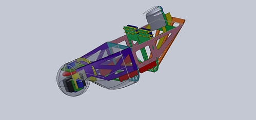
new design i am working on . built around sony FCB-EX11D 10x optical zoom block camera
this camera can be controlled through rs-232 com and has many cool features including built - in OSD
The little airplane is able to withstand rough conditions thanks to three aeroservoelastic trim tabs, which are located on the trailing edges of the wings and tail. When the plane is hit by wind gusts, the tabs perform rapid high-frequency shape changes, to counteract the effects of the wind. The technology is not unlike the shape-changing trailing edge flaps currently being developed to protect wind turbines from destructive gusts. Combined with several other features, such as a special aerofoil profile optimized for high lift at low speeds, the result is a remarkably steady aircraft.
We've been working hard to make MatrixPilot ever more modular, and to test this modularization, I thought it would be fun to build a LOGO-like mission planning language as a plug-in replacement for the existing waypoints module.
After a few evenings of playing, I ended up with something that actually feels pretty useful. All the logo basics are there: HOME, RT, LT, FD, BK, REPEAT, etc. You can also set specific locations (like traditional waypoints), set altitude, and set and toggle flags like whether to fly inverted. You can also toggle between controlling the plane, and controlling the camera target. More info on the language here.
The above image is from a simulation of the following UDB LOGO program running in XPlane using MatrixPilot's HIL Simulation.
// 10-pointed star with an external loop at each point
REPEAT(10)
// One leg of the star
FD(2000)
// Turn 180 + 72 degrees over the course of 18 small segments
REPEAT(18)
RT(14) // RT( (180+72)/18 )
FD(50)
END
END
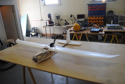
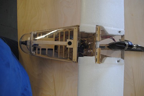
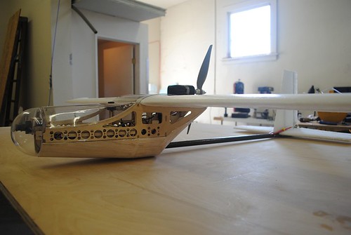
SPECS:
cruise speed - 27knots
max speed - 55knots
max weight - 4.4 lbs
flight time - 1 hour+
climb rate - 2000 ft/min
features :
EPP wings and tail
carbon fiber tail boom
clear lexan ,fully removable top hatches
clear acrylic "camera quality" dome
pan/tilt camera mount
retail price will be approx $150-$200
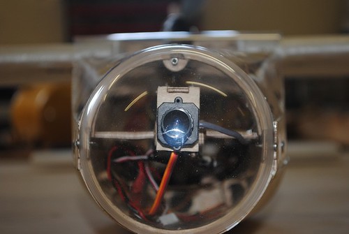
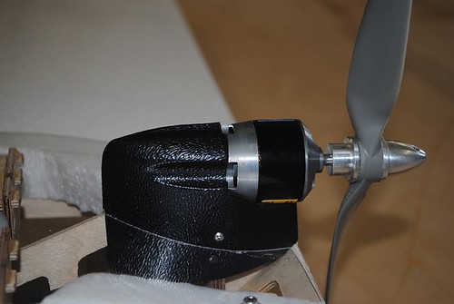
my activity on this site has been low for the past year as i have been up to my ears with starting a business and developing a few products for us to sell . I would encourage anyone reading this to take a good long look at my profile so as to understand my background and my history with the diydrones community .
As most are aware , the only true constant in life is change . However the rate of change would appear to be on the uprise . most of us at this point either have lost our jobs or at least know someone who has . This in turn has a ripple effect on the economy , not just as a whole but an individuals economy . The effects of the present state of the economy have been effecting the world of open source . this can be demonstrated very easily by noting Blogs such as Chris's "update on product availability " , the disappearance of projects such as open pilot (I've been trying to contact the team with no success and the latest activity was back in June . if anyone has more info please let me know.). Lets face it , its hard to develop complicated machinery with no capital.
the future of open source autopilots are not guaranteed . as with everything in life open source autopilots are going to have to change or die . OSAP (open source autopilots) have been facing many problems from all sides .
These include but not limited to government regulations , inter-OSAP competition , bad economy , "race to the bottom" mentality , "open source = no $" mentality , no single self regulation entity (AMA for UAVs),and many other fears and misconception held by the public at large and OSAP developers.
The question at hand is this : how can OSAPs change so as not to die ?
I believe the answer is to draw from the strengths that both "open source" and "commercial" auto pilots enjoy
#1 co-operation . as individuals we will be broken one by one , If we join forces we can be unstoppable
#2 commercial viability . the most successful open source projects have commercial applications . no income = no output.
#3 self regulation . Ive been told directly from FAA officials and can be read here ARC.pdf . we have to self regulate or the government will be stepping in .
#4 we , as a whole , need to stop making decisions based on fear . logic yes , fear no
If you are flying a UAV DevBoard in a plane without ailerons, you should be interested in a recent revision to MatrixPilot that will tighten the turns in waypoint mode, without overshoot. The above picture is the track of a portion of a test flight in an EasyStar. The control mode was switched from stabilized mode to waypoint mode with the EasyStar flying away from the first waypoint. So the controls performed a tight (less than 15 meter radius) "snap-turn", with very little overshoot.
Up until now, the only way to prevent turning overshoot with MatrixPilot was to use a large value for the yaw damping parameter. Although that certainly prevented overshoot, it made the turns very wide. The latest revision prevents overshoot, while still enabling tight turns.
The revision is rather simple: an optional negative feedback term equal to a gain times the roll has been added to the rudder control. The effect is to reduce the steering time constant. It is equivalent to controlling the roll rather than the yaw rate. It is something that has been on my list to do for a long time, I finally got around to it. Rana and Sid have been using this feature unofficially for some time, they encouraged me to add it. Also, there have been posts from time to time from other authors recommending roll-based steering. MatrixPilot has always used roll-based steering with ailerons, but until now, for mostly historical reasons, it used yaw-based steering with rudder.
The new parameter is ROLLKP_RUDDER in the options.h file of MatrixPilot. It is now available in MatrixPilot2.5 in the branches directory, or in the "developers" version in the project main trunk, or as a version 2.5.1 zip file. If you want to try it out, to start with set ROLLKP_RUDDER to the same value as YAWKP_RUDDER. For an EasyStar, set them both to 0.15, and set YAWKD_RUDDER to 0. For now, leave "dead-reckoning" and "cross-tracking" turned off, I am working on improving the performance of both of those. Right now they are not performing up to their potential.
The following is a portion of the track during a test with an EasyStar in which ROLLKP_RUDDER was deliberately set to 0, with YAWKP_RUDDER = 0.15, and a modest value of YAWKD_RUDDER (I forgot what it was.) to show what happens without rudder-roll stabilization. Note the large amount of slowly decaying overshoot after the snap turns.
So, if you are using MatrixPilot in a plane without ailerons, I highly recommend trying this new feature, it should improve waypoint performance.
Best regards,
Bill
Here's a copy of our Deliverable 2 video that we presented for entry into the 2010 UAV Outback Challenge.
We are using a Penguin-B UAV airframe from UAVFactory(.com) its a very stable platform and as seen in the video it is flying at an AUW of 15kg (~30lb) and tootling along at 1/3rd throttle.
Thought some of you might find it interesting....enjoy.
Spotted at the DefCon hacker conference this year, the ArduPilot-powered WiFi Aerial Surveillance Platform (WASP), basically a UAV with WiFi sniffing capability. It flies until it finds an open WiFi access point and then loiters over it. Here's a video interview with the creators at the conference:
Jason Short has made it easy for ArduPilot users. In the Events tab of 2.7, there is an example of egg-drop code that even has an equation to calculate the proper distance from the target. It assumes you've added Channel 4 control to your ArduPilot. Just set a waypoint for your egg (it's waypoint 3 in the sample code below), hook Channel 4 to a servo that releases the egg, and start dropping!
"void mediumLoop_event(void)
{
/*
float temp = (float)(current_loc.alt - home.alt) * .01;
egg_dist = sqrt(temp / 4.903) * (float)ground_speed *.01;
if(wp_index == 3){
wp_radius = 10;
if(wp_distance < egg_dist){
servo_out[CH_RUDDER] = PAYLOAD_OPEN;
}
}else{
wp_radius = 20;
servo_out[CH_RUDDER] = PAYLOAD_CLOSED;
}
*/
}
Consider this post by the respected DIY ESC developer Takao Shimizu, talking about a low cost controller available from a popular vendor:
The money quote:
But, when it's over the current (>2A), then the output voltage goes up to the input voltage(11.4V).
Read that carefully: if you overload the ESC (and 2A isn't that much of a load), your 5V supply suddenly becomes an 11.4V (or higher) supply. Think about how much you have invested in your receiver, servos, autopilot, GPS, OSD, camera(s), etc. Many (most) would be destroyed more or less instantly by a surge of that kind.
It's not just power supplies, though. Cheap servos are tempting too, but again they represent a single point of failure for your aircraft. If you're just building a foamie with an anticipated flying life of a few months, you might be willing to accept the occasional failure and early demise, but if you're flying several hundred dollars worth of gear, a few bucks more for decent servos is a much better investment.

