Ferreting around sUAS News for something else I am working on I stumbled on this video, 2009 no less! How things have changed. Hope folks don't mind me posting it here again.
All Posts (14048)
Sort by
That my list of 9x radio mods, Keeping it DIY, and under $200 :)
First one is 'er9x' firmware super easy:
Here is wiki page and good 'How to wire' videos: Part 1 Part 2 Part 3 you'll need some programmer this one works fine
also you can use arduino board.
'eepe' tool is here.
Next one is the 6 position 'mode' switch for ArduPlane/Copter, here is my original mod and complete 'how to' from Paul. That is 2 pole switch, so its 2 switches in one and I used that second switch for LEDs.
Next is the Turnigy 9X LCD Backlight Kit from HK 'how to' is here :) IMPORTANT !!! DON'T DO THAT
.jpg)
Just cut-off some of extra foam but don't try to completely remove it, big mess !
Speaker Mod with Haptic Feedback really cool one :)
Next FrSky Telemetry
There is number of ways to do it 'How to modify your 9x to support telemetry'
one is using 'FrSkyLite' that also used for 'FrSky' firmware upgrades.
But here is another one that also converts 'FrSky' module to support firmware upgrades via FTDI cable.
You'll need to perform minor surgery on that DHT DIY module :)
And some work on the 9x board too.
But the most important part is the new ERSKY9x ARM board for 9x radios !!!
Here is a Feature List:
input voltage 6.5 - 16 volts (7.2V ideal)
Atmel SAM3S ARM Cortex M3 Microprocessor
256K of Eprom , 48K Ram
4mb EEprom - For Model /sound storage
Support for Optrex display F-55472GNFJ-SLW-AAN
Built-in external USB socket for Programming / interface.
2 external RS232 Serial Ports.
PWM control of LED backlight . (dimmable)
1/2 Watt Mono Audio Amp , with digital volume control
8 ohm speaker output with auto switch over headphone jack output.
Micro SD card socket with 4 bit high speed connection to ARM
Support for RN-42 Bluetooth Module (spot for external TTL serial connection)
Haptic output connector , with PWM drive.
ATTiny167 AVR micro for RTC and 12 external switch inputs/encoders or up to 10 A/D inputs , can be battery backuped
External I/O connector with 4 lines one with DAC output
I2C output connector + spare port pin.
5V output.
On board current sensor , to measure power usage on battery
Second PPM OUTPUT
Software control of Power - off
Should be out soon for $85 !
Drones are everywhere, and drones enthusiasts too.
Today we're happy to announce the launch of CroissantCopter, the first franchise to the already world-knownTacocopter but this time delivering croissants in Paris !
If you're in Paris, we're recruiting cooks and pilots :)
It's time for the third round of the third round of the second season of the Trust Time Trial (T3) competion! Now that the weather is improving, there are no excuses for not participating. Valuable prizes await!
This the Reliability Round. Our Judge, Gary Mortimer, describes the rules below:
-------------------------------------- RULES ------------------------
Point of order first: All T3 entries should be flown away from built up areas. Should you have any fly aways or incidents its best to have them miles from anyone else.
The aim of this round is to show reliability.
A very simple task: autonomously fly to a point that you have chosen that is at least 300 metres from your takeoff point (100m for copters). At an altitude of 75 meters (25m for copters) autonomously take a single photo of your point, then return to launch, land (manually or autonomously) and do it all again. Repeat this for a total of five flights.
Your entry should show your take off and landing times for each flight as well as KMLs showing the slight path. As always, post your entries in the comments below.
Each individual image will be compared and the person with the most shots with the chosen point in the centre of the image wins.
Honesty is everything here, don't discover that by chance a point you didn't select is in the centre of each shot and then tell us that's what you were after all along.
But.....
If you can make something interesting with your shots extra points will be forthcoming
You might make a map using MapKnitter. Have a look around here to find out what its all about here. Do something with Photosynth, ICE or any of the other similar mapping products springing up. Wouldn't it be nice to have a DIYD generated layer of opensource map images out there!
So in summary one day, five flights, five photos. Extra points for creative use of mapping software/services.
What you do with any other images is up to you. Impress us.
Why the pub challenges in the image above? Well I was looking at a dart board when I thought of it.
As an aside the area in the picture will be underwater next year, a dam wall is being built on the right. The big circles are irrigation centre pivots just the sort of thing a farmer might be interested at looking at from a UAS
-----------------------------------------------------------
There will be three winners in each category (planes and copters), with the #1s getting a $100 gift certificate at the DIY Drones store and #2 and #3 getting $25 each.
All entrants who successfully compete the course with a copter, regardless of place in the judging, will receive a flying robot merit badge!
Deadline is Sunday, May 13th, at midnight PST.
Another title might be "How long before we kill someone?".
Why such a provocative title? Well, a few days ago a fellow RC enthusiast approached me brimming with pride and sense of accomplishment. He wanted to tell me how he had flow his FPV RC airplane up to 3500 feet and in the clouds and successfully brought it back to it's launch location. I commended him on his technical achievement and his flying skills but, I was aghast and shocked by his mission. You see I'm also an instrument rated fixed wing and helicopter pilot and I know and fly in this area all the time. The area where we live is one of the most busy and congested airspaces in the country. Even worse, I knew the field this young man was flying out of was directly under the approach path for a major international airport where airplanes are required to be at 2500' directly over that field as they approach the airport and everything from small Cessna to hugh 747's fly through that spot at approximately one per minute. As well aircraft not approaching that major airport are required to be below 2000' feet when they transition the area. Turns out that field is also immediately adjacent to a popular ATC reporting point where ATC will ask aircraft under their control to fly to and then report having reached.
Do you see the problem? If not, and you are an RC enthusiast you best get a different hobby. Especially if you fly sailplanes or FPV. It was just pure luck or the grace of God (if you are a believer) that one of those airliners traveling 250 knots (about a mile every 15 seconds) didn't collide or have a near miss with my friends aircraft! He stated he had spotters but that it was also overcast so there was NO WAY his spotters could have seen any full sized aircraft let alone his own RC aircraft. Even if they could does any one honestly believe they could get out of the way fast enough if they saw a full size aircraft burst out of the clouds at a mile every 15 seconds? If they were able to it would be much luck.
Of course this is a worst case scenario and every bit of it is true - that's what prompted me to make this blog entry. Many of you fly in far less congested airspace but the risks are still there. I've seen many videos and blog entries from guys who were so proud about their FPV flight all over some city or elsewhere at altitudes where full size aircraft fly. It's pretty rampant.
The fact is, a full size aircraft colliding with one of our RC aircraft is in for a world of hurt. Our RC aircraft are near the size and weight of birds which bring down multiple aircraft a year except that birds can make much quicker decisions to get out of the way.You see, a two pound RC aircraft hit by an aircraft doing between 80 and 250 miles per hour is going to go right through the windshield of any airplane and likely will take the head off of the pilot behind it. And if it hits a control surface it could make the aircraft unflyable or if it get's sucked into an engine, it could make the engine explode. Very high probability of serious injury or death here.
So what are the consequences? I just told what they are for pilots and airline passengers - injury or death. For RC enthusiasts even if all you do is cause an aircraft to make an emergency deviation or landing it's going to get LOTS of press and the FAA will take action. The first time this happens you can bet our friendly representatives like Feinstein and Boxer will force the FAA (if they won't do it on their own which they likely will anyway) to enact strict new laws highly restrictive to RC flying. They've already written them. Their just waiting for the ammunition that will garner enough public support where it won't matter a bit as to what we RC enthusiasts say. Then we'll likely have to get permits, licenses, etc. and be very restricted to where we can fly - if we can fly at all.
In the case where an RC enthusiasts causes a fatality or a crash. Not only will the FAA go berserk and take the previously mentioned actions but the RCer will be going to jail. Simply causing a crash will likely get you 5 years but if you cause a death that's going to be manslaughter and if they can prove that you knew the risk it'll be second degree murder. Either way you'll be going to jail for at least 25 years. If it's only manslaughter you probably will be able to get out after 10 years if you have no prior record and behave well while in prison. That's the good news.
So, the bottom line is will this happen? The answer is yes because nothing I wrote is new news and we all see blogs and forum posts from people bragging about their exploits flying high, flying over people, etc. etc. It's really just a matter of time. We'll all suffer from lost privileges but, more importantly, the victims and their families will suffer - people killed so some irresponsible person can have 20 minutes of fun with their RC aircraft. And last, some RCer will suffer more than the rest. He'll like be a smart talented individual who had a lapse of judgement thinking "It won't happen to me. I do it all the time and have never had a problem" (popular answer right? "I do it all the time and never had a problem"). All it takes is that FIRST time and it's all over.
So, you think this is unlikely to happen? You think that if it does happen that the instigator is unlikely to get prosecuted and sent to jail? Well, you should educate yourself. Every year, licensed aircraft pilots are fined tens of thousands of dollars and sent to jail for violating airspace and for causing accidents, deaths or even near misses (if negligence was found). Recently, the pilot of a Cessna 172 nearly collided with a small biz jet forcing the pilots to take evasive action where by they ultimate crashed and were killed. The Cessna pilot was flying in could without being under a flight plan and without an instrument rating. He was convicted of second degree murder and is serving 25 to life. I see no reason why an RCer who causes an equally serious accident wouldn't be treated equally.
AMA already has guidelines for us - stay under 400 feet within 3 miles of an airport which help but aren't good enough. They guy flying at 3500 feet was 5 miles from the airport so technically he was following AMA rules but he was totally ignorant of what was actually going on around and above him. The problem with the AMA rules is they were clearly drafted by people who know little about how full size aircraft actually navigate. The only thing that will help is for people flying these machines to get educated on where they are flying and to use good judgement. Problem is many will not get educated and we already know there are some who lack or have a different definition of what good judgement is. I'm definitely not an advocate of more government rules and regs so I sit torn on the matter. How do we prevent a major incident from happening in our current environment? I'm not feeling too positive about a solution that doesn't negatively impact us all and I expect there will be an incident which will compel the FAA to take harsh and restrictive action.
(photo of the results of a UAV collision with a C130 added by the Moderators to comply with site guidelines that all posts have have an appropriate picture)
It's a hour-long documentary that just went live on Dutch TV, which you can watch here. The DIY Drones/3D Robotics stuff starts at about 25:00. It's about 50% spoken English with Dutch subtitles, and is really well done. There's an interview with me at the Wired offices and then shots from the 3D Robotics factory. Lots of other great video from interviews at ETH, as well some Kinect motion-control drone demos.
Sadly the embedding doesn't seem to work, so go to the link above to watch it.
Hello DiyDroners,
I recently completed the implementation of a new feature for ArduPlane & ArduCopter. I have to thank Jan Scherrer for the idea and especially thank Andrew Tridgell for pushing me to improve the original implementation. The new feature is automatic compass declination.
Currently you are supposed to look up the magnetic declination value for your flight location and input that value into the Mission Planner so the compass heading can be corrected. If you are like me and constantly flying at new locations, it is a bit annoying to have to look this up every single time. In this post, Jan asked why it couldn't just be automatic... I did not have an answer so I decided to see if I could make that happen.
USAGE:
The automatic declination code is enabled by default. There is a new configuration parameter you can set in the Mission Planner if you wish to disable/re-enable it. See below:
To enable, set COMPASS_AUTODEC to 1. To disable, set COMPASS_AUTODEC to 0.
After any parameter changes you need to click the "Write Params" button.
With automatic declination enabled, the declination will be approximated to the declination at your GPS Lat/Lng coordinates as soon as a 3D fix is acquired. So far from our tests we show a +/- error of .5 degrees depending on your location. Andrew Tridgell reported accuracy of within .3 and I am seeing accuracy within .05.
The latest code that includes the automatic declination is available in the git repository. I should warn you that while most of the code in there is already tested, some of it may not be because that git repository is constantly in flux. If you feel confident, give it a try! The more testers the better. Otherwise, if you prefer to wait, this feature will be included in the next official release.
TECHNICAL:
What is magnetic declination? Good question...Read this
I ended up finding another person that had put together a look up data table that used bi-linear interpolation to pull an approximate declination based on lat/lng GPS coordinates. This was definitely a good start. So I took that code and adapted it for our code base (of course giving proper credit to the original author). The problem with the original implementation was that the look up table took up a massive amount of space ( > 5kb ) and the way I had originally written it, that look up table was being stored in RAM instead of flash memory. Without going into too much detail on the difference between those two types of memory, the first is memory that is volatile memory that is used to store variables during code execution. It is fast, but resources are limited. Because the look up table is a static set of data that gets used infrequently, it is a much better option to store it in the flash memory (using PROGMEM). You can read about it all here.
Ok... so how to go from a 5kb to a lot less. We are dealing with integer values which vary in size. The first thing we need to do is make sure that we are using the smallest possible integer size for the values that we have in the look up table. The range of values in the original table -99 to 179. So out of the standard int sizes (int8_t, int16_t and int32_t) int16_t is the smallest we could use with a supported range of -32768 to 32767. The next smallest size, int8_t, supports a range of -128 to 127. You can see that the the lower end of the look up values will fit (-99 is greater than -128), but the upper range will not (179 is greater than the allowed 127).
Turns out there are a lot of clever ways to compress data. Here are a few that I considered, some of which I used.
1. Shift all the values -52 bringing the highest value in the look up table to 127 which is within int8_t. Oops that doesn't work. Now the lower end exceeds the lower limit of int8_t.
2. Store the first value in each row and then the differences between each consecutive value instead of the values themselves. This is a very promising approach because the difference between each value is quite small, meaning we can use a smaller integer size to store the value.
3. Pack the sign bits in a different array.
Lets take the highest value in the array (179) and see what that means in terms of a 16bit integer. 179 is represented by the following:
0000000010110011
You can see that the upper 8 bits are not used (all zeros), but unfortunately we need at least one more bit to represent the sign of the lower end values. All of our values can fit into 9 bits, but when you create a 9 bit integer it is automatically padded up to 16 bits. What we could do is take all the extra sign bits out of the original array and put them in their own array. That means all of the absolutevalues fit in 8bits (a good improvement over the 16bits before, half the space). So how do we pack those sign bits? Remember that I said that the number of bits is automatically rounded up to the nearest byte. That means that if we tried to declare a 1 bit int for the sign and store it, it would actually take up 8 bits. Take the following:
00000001 - this would represent negative
00000000 - this would represent positive
All we need is that one value (1 or 0) to say that it is either negative or positive. So what we can do to avoid wasting those other 7 bits is to store 7 more signs in that one byte.
Take these values -99, 75, 43, -23, 175, 132, -45, -32
So that would be: 10010011 (1s for negative signs, zeros for the positive signs)
Now we are taking advantage of the full byte (8 bits) and not losing any space because of the padded bits.
Using a combination of the above methods allowed me to pack the values into around 1.6kb. When you compress the values, the retrieval strategy must change. Normally you would access values in an array using this simple syntax. MyArray[12][2] which means give me the value in the 13th row, 3rd column. If we are splitting the array into their starting values, consecutive delta values, and signs, we will need to pull those values out in a different way. If you are interested in learning how it works, feel free to check out the code from the git repository. The logic is located in the AP_Declination.cpp file in the libraries folder.
As always, questions are welcome!
Thanks,
Adam
It flies!!!
Finished the Raptor this week, it was a blast to make, I think I'm falling in love with flying wings. After installing all the electronics I was super happy to discover that their placement made for a great nose heavy CG, and no dead weight would be needed.
Took it out to the field, did some range testing and CG testing, and then used a "frisbee" style hand launch. Took a few tries, but I finally got it in the air. Flies amazing, very very agile, too agile actually. I'll need to reduce the throws on the elevons to add more control. It glides very, very well. It may even glide better then the Nova, seriously, that is how well it glides.
More testing next week!
-Trent
 Y650 Scorpion multi-rotor frame is a high quality glass fiber frame that offers both great looks and performance. Built from light weight yet extremely rigid glass fiber and aluminum, the Y650 offers a great combination of weight savings and strength.
The Y650s aggressive styling makes it look more like a deadly creature than a multi-rotor frame, while still offering excellent functionality and performance!
This multi-rotor frame is designed for use in the "Y-6" configuration utilizing 6 motors (3 mounted above and 3 mounted below).
Specifications:
Width: 650mm
Motor Bolt Holes: 32~40mm
Frame Weight: 410g (w/out electronics)
More information at Hobbyking: http://www.hobbyking.com/hobbyking/store/uh_viewitem.asp?idproduct=22801
From the description:
This is my new pan-tilt-roll gimbal for my GoPro HD camera. It is supposed to go onto a remote controlled airplane for FPV and aerial video. The whole mechanical structure was printed (laser sintered) by Shapeways.
http://www.shapeways.com/model/207257/3_axis_camera_gimbal_for_gopro__back_ca...
This test shows the first test of 3-axis gyro stabilisation. It still needs a lot of tweaking (I already made a few improvements - stand by...). Here the gyro sensors are on the mount (i.e. will be on the plane, also for the stabilisation of the plane itself). In the final version there will be another gyro sensor directly on the camera, which should make it much more precise.
I participated in a great Drone Journalism meetup at the Storify offices in San Francisco last night, with packed house of attendees. Other panelists were Matt Waite of the University of Nebraska Drone Journalism Lab, Tyler Brown of the Occucopter project, Jennifer Lynch of the EFF and Ryan Calo of Stanford University Law School.
Jim Swanson also brought his big Mikrokopter octo (above), mostly to spin the props so people would know I was serious when I called multicopters "flying lawnmowers". (My point is that it's dangerous and illegal to fly these things over crowds, as some of the more naive drone journalism advocates want to do).
The panelists described what was possible with drones today, but focused even more on safety, legality and practicality. You can read a Storify report on the evening here.
Here's me with one of Tyler's quads.
Hey everyone,
Quick update regarding dronemapper.com. Big thanks to all the best test users who have been helping me work out plenty of bugs and also get certain data formats more reliable. TLOG processing is working and now using the correct log fields, for the best results we have found you should have a magnetometer installed. :) There are a couple of cool new features:
- SRTM3 DEM Data of your flight region, large and trimmed GeoTiffs are generated.
- 3D Mosaic Blending, 3D DEM and 3D Model generation. (roughly based on Andrew Hazelden's approach)
- Improved Ardu GPX/TLOG processing.
- Improved "blended" 2D mosaic generation. Lots of bug fixes!
- TLOG Processing via MAVLink Graph
Definitely a lot of work and refinement left but I am not so discouraged. :D
Output .PLY file downloaded and viewed in MeshLab. I hope to have an online viewer like Hypr3d shortly.
Imagery Courtesy: Martin R.
Mikrokopter Platform: 43 Images, 25 Used in 3D Mode
Thanks to everyone involved.
Best,
JP
Want to play with the awesome Invensense MPU-6000/6050 sensor used by APM 2 but struggling with the fine-pitch surface mount form factor? Sparkfun has come to your rescue with this handy breakout board version of the 6050. They're a little expensive at $40 each, but it's a great chip and very much the future of aerial robotics.
(BTW, the difference between the MPU-6000 and the MPU-6050 is that the first uses a SPI data interface and the second is I2C)
For the last six month we (my friend and I) have been working on the development of autopilot. We called it SmartAP - Smart Autopilot.
It's all started in October 2011, when I decided to try to build our own autopilot, designed using the latest components.
Firstly, we purchased evaluation boards for a desired microcontroller, we have chosen STM32F103, based on ARM Cortex M3. Then we started to build autopilot step by step-by-step from the scratch on the breadboard, creating preliminary version of the software.
A couple of month later we had been focused on the autopilot hardware. We made our own PCB design, ordered several PCBs and SMD electronic components to produce several boards for tests. The last step was placing components on PCBs and it was done two days ago (unfortunately, MPU-6050 is missed, due to some shipment delays, we are expecting it to be delivered next week).
Yesterday was the first power-on test and all works fine!
Here is the bottom view:
Now we are working on the first final version of the software to make maiden flight. Also we are thinking about implementing some interesting features, which no one of existing autopilots has today.
We don't know exactly about the future development of this project (we definitely continue to work on this), but if there will be a demand for this, we might establish mass production and start sales.
Here are some main features:
PCB size 60x40mm, (4 layers), weight 14g
72MHz STM32 ARM Cortex M3 microcontroller
6 PWM inputs, 6 PWM outputs
IMU - Invensense MPU-6050 (using internal DMP)
Magnetometer - HMC5883
Pressure sensor - BMP085 (I wanted to use MS5611, but it was very difficult to order it)
UART port for wireless telemetry connection (e.g. Xbee)
MicroSD card slot for flight data logging
GPS port
Sonar port
Airspeed sensor port
I'm very greatful to DIYDrones community and 3DRobotics company! A year of experience with ArduPilot Mega gave me an inspiration and good knowledge in this area, which made possible for me to build my own autopilot.
If you have any questions - feel free to ask them.
Kirill
Since my last post I have been working on building a cheap RC sailboat. And I must say that the feedback I got from the community has been very helpful. So special thanks to people who showed their interest and gave me tips.
My aim is to eventually build an autonomous sailor, and a RC one is just a step in between. The “Catamaran” which you see in the pictures is radio controlled and I have tested it on water. However there is more work to do, the final RC boat will be even more cheaper and better. The reason for that is because I want to provide an accessible platform, which is easily built and is not as expensive as a toy boat. In that way anybody interested can start developing autonomous sailors. Within two weeks I hope to have the final RC version and I will share the instructions with you.
I am also going to prepare five kits with all the materials and instructions you’ll need to build one, excluding the electronics.
So, if you are interested to get involved mail to sina.sailorkit@gmail.comand I will ship one of the kits to you, if your on time. You don’t need to pay.
If you have received the kit, I would appreciate if you also join the autonomous sailor group and share your experience with the community.
Note I can only provide five kits :)
Cheers,
Sina
The ArduIMU v3 is a very interesting little device for minimalists. For my own project, I needed a device that could keep the plane level, maintain heading/altitude and sometimes steer to a particular waypoint. The majority of the time, I intend to control the plane myself, but I need the autopilot to take over at certain times to allow me to perform some other minor tasks. This is a video showing a full 'hardware-in-the-loop' demonstration of the IMU with only the platform replaced by the flightgear simulator. Manual control is effected by a wii motion+, which is held in the angle that I want the plane to be. Pressing the "B" (actuator) button means I take over control manually, letting it go allows the imu to take over and maintain course/altitude.
The Ardu IMU v3 ticks all the boxes in terms of inputs, outputs, size and price. My requirements:
- Keep a plane level in a certain direction at a certain attitude when there is no overriding control input
- Fly home in failsafe conditions and land after x seconds.
- Send down telemetry of the entire sensor array, servo commands and specific autopilot messages at a frequency of at least 10Hz with a goal of 30 Hz.
- Very small form factor and at least one spi, i2c and analog bus free.
- I wanted to push the code complexity of navigation and autonomy from the plane back to the ground, where debugging and verification is easier, which also highly facilitates debugging, as everything can be connected to simulators. It's clear that I'm making the assumption that I can guarantee the stability and availability of a two-way datalink at a high bitrate.
Instead of a fully autonomous system, this project explores the requirements for a system where the pilot is kept closer in the loop and where the role of this single operator changes frequently during the flight. Piloting, navigation and mission execution are seen as three different concerns that are hierarchically associated. What this hopes to achieve is to smoothen out the cognitive consequences of changes in context and situation that occurs when operators switch between these roles and what is needed in terms of technology and displays to help the operator make that transition. The more fluid this transition is perceived to be, the better the system is perceived.
The other very interesting benefit is that, if the assumption of the datalink guarantee holds, the kind of applications that become possible are very interesting. This is especially the case in situations where a lot of data is available on the ground, which cannot be easily sent or stored on the platform (realtime data about ground movements, collaborative searches, etc. ). This paves the way for a rich augmented reality display, where positions of interest, movements of other mobile objects, home locations, antenna beam limits and landing tunnels can be visualized virtually, supporting the flight operations of the pilot. The assumption being that merging a symbolic, graphical display with actual video, instead of showing numbers and arrows that require interpretation is significantly better.
I personally foresee that it makes more sense to move back the navigation+piloting code from the ground to the plane eventually, but this is a great starting point for systems where the tasks for navigation and mission control could blend in more with the actual environment of the plane.
Thanks to our friends at Tacocopter, who decided to base their only slightly imaginary robotic food delivery service on the ArduCopter platform, we have now made the big time: The Colbert Report does a whole segment on ArduCopter-powered fictional food transport.
I've been struggling to understand how to get the APM failsafe working properly and have yet to find some clear instructions that a noob like I can follow. It suddenly dawned on me how to get it all setup.
Here is my normal zero throttle output:
Here it is when the radio is off:
The AR8000 can be taught what to do if it looses contact with the mothership. The default is to leave or move the throttle to zero. As you can see, zero is normal and not enough to invoke the APM failsafe. (see here for more info on the APM Failsafe: http://code.google.com/p/arducopter/wiki/AC2_Failsafe)
What you need to do is tell the AR8000 to go below zero when the radio is lost and here's how you do it:
- Turn on the radio and go into servo setup.
- Find the throttle travel setup (on the DX8 it's the first screen)
- Scroll down to negative travel (Left hand 100%). Change that to as high as it'll go. 140% in my case.
- Confirm in Mission Planner that throttle input is now around 920uS
- Turn off radio and receiver.
- Insert Bind plug into RX and turn on.
- Remove bind plug from rx. Light should continue blinking.
- Ensure throttle stick is down.
- Turn on radio while holding down bind button. Radio should rebind.
- Turn everything off.
- Turn radio back on and change the throttle throw back to 100%
- Turn on quad and connection with MP
- Confirm that minimum throttle is back to around 1100.
- Turn off radio and throttle should now drop to around 920uS (or whatever it was beforehand)
- If not, start again.
- Now go to parameters in MP
- Find THR_FAILSAFE and set it to 1.
- Find THR_FS_ACTION and set it to 2 (1 = continue on Auto mission, 2 is RTL)
- Click on the write params.
- Click on Refresh to ensure it wrote it.
What you have done is told the receiver that when you loose contact, this is the new throttle position. It is of course, way lower than normal range. The low value is enough to trigger the APM failsafe which will RTL and land.
This all works in theory for me and MP seems to agree, I'll be out testing it tomorrow but just wanted to get it all down on paper so to speak.
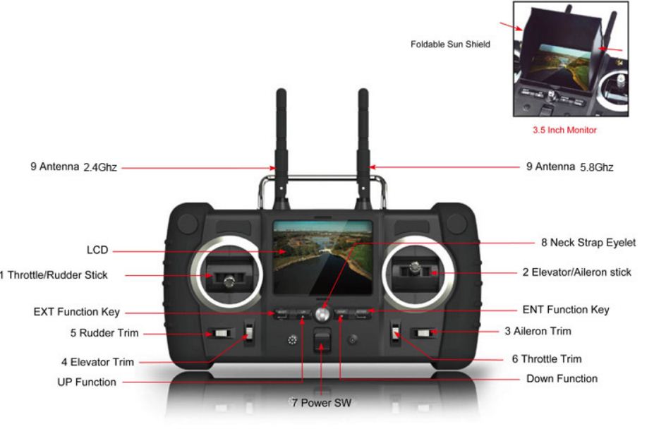
My money is on a few people buying the systems just for the video downlink and screen.
Lets see how the first few review ones fly.
http://www.suasnews.com/2012/03/13932/ready-to-fly-first-person-view-aircraft/
Hi Everyone,
Maybe you remember, last week my 200mm size quadrocopter (MQ-200) was lifted a GoPro.
After outdoor flight under 15-20km wind conditions without any problem, i designed MQ-202.
It is same size microquadro but including landing gears and more rigid than MQ-200.
MQ-202 flying with OpenLRS Multi board with MultiWii code. If you interesting, I just released the code in the MultiWii repository .
This weekend i will test Magnetometer and GPS functions(RTH and waypoints).
I think these small size quads sufficient for some tasks (FPV patrol or taking video with gopro). We will try and learn their limits :)
Cheers
Melih
Last video from my retired MQ-200 :)