All Posts (14056)

Sort by

(THIS TOPIC IS BEING DISCUSSED HERE)


I've never introduced myself so I'll take the time now (feel free to skip this paragraph). I have a business background but I am a technology enthusiast. Recently my interest about the business and strategics/social aspects of Open Source (especially Open Hardware) has really grown. In order to better understand the OS movement (and satisfy my geek alterego) I have been tinkering with Arduino, learning some programming languages, etc. And then I learned about DIY Drones....Once upon a time I flew RC Planes (that was during 1995 and 1996, I believe). I've been wanting to restart the hobby for quite some time, but now I believe I have what it takes ($). Unfortunately I live in a city that is not very RC-plane-friendly and I don't have a park or something nearby. For that reason I've been considering a Quadcopter project (for the VTOL and stability characteristics). This project should not only satisfy my flying needs, but also teach me about electronics, programming, etc.I am thinking about using a platform based on Arduino since I have learned some programming on it. Currently I am leaning towards the AeroQuad.In the future (if the thing take-offs) I plan on installing video gear for FPV. Followed by that I plan on programming (or if I get lazy I'll just buy a kit) some OSD. And than I should go into the UAV territory.I have many doubts about the project... here are some that maybe someone can help clarify:
  • Is the AeroQuad the best choice for what I need now and plan on installing in the future?
  • How much thrust do I need for something like this?
  • Does the AeroQuad support X configuration (I've only seen + configuration), and is that a hard thing to change?
  • Is a Quadcopter a good platform for UAVs?
  • Can a Quadcopter develop good forward speed? I imagine it to be slower than a heli. I haven't seen any movies of people flying quad's on long distances (which is something I'd like to do).
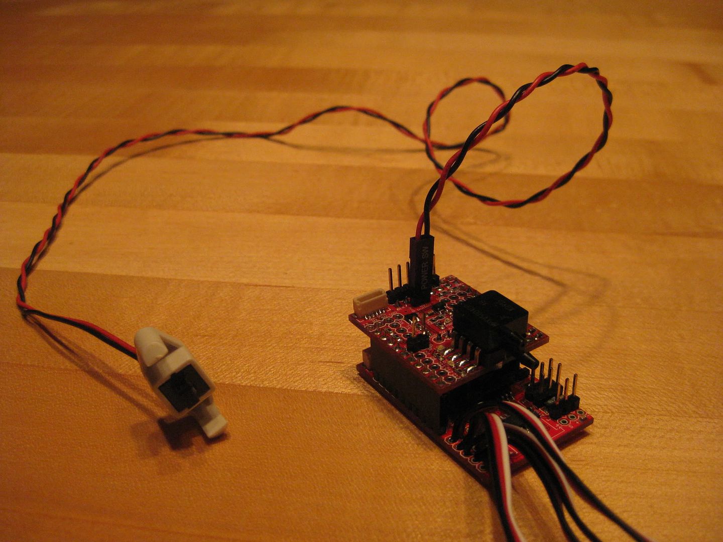
Based on my needs I believe this will be a VERY long (and probably expensive) project. I do want to discover the best COSTxBENEFIT solutions, of course.The "foward speed" thing is a factor that will probably take me into a next step that will be to transform the Quadcopter into a mix of Quad/V-22 Osprey/Airplane (that's why I have the question about the X configuration). Does anyone know a project like this?Sorry about the long post, I hope someone has the patience to read it.

(THIS TOPIC IS BEING DISCUSSED HERE)


Read more…
3D Robotics
Gary Mortimer has a good idea: a DIY time trial contest, where you time your UAV flying autonomously over an agreed-upon course. You upload GPS track, time and, onboard video. Fastest time each month wins something cool that I'll donate (like a Funjet kit). What kind of course would work best for this? For starters, how about this: a square, 400m on a side. Must complete three full circuits in fully autonomous mode. Carry an onboard GPS datalogger or datalog from your telemetry stream and upload the file (so people can see timestamps). How does that sound? (pic stolen from Gary's comment below)
Read more…

Ardupilot roll functional flow diagram

I'm installing Ardupilot in the 6 foot wingspan electric Telemaster. As this is a significantly different airplane than the Easy Star I want to proceed slowly and carefully. If I can I am going to adjust and confirm PID settings, etc, one function (roll, climb and speed) at a time, starting with roll. I decided I needed to have a good idea how the roll software is implemented in Jordi's and Chris' marvellous software. So I embarked on developing the functional flow diagram shown here. It is based on V2.2.3roll_flow_chart.pdfI'm a noobie at this so I don't claim it is 100% accurate although I think it is close. Doing this has been a good education for me but I wonder if it is useful to others. I would be interested in Ardupilot enthusiasts' comments, including suggestions for corrections and/or improvements.By the way, the term "heading" is used incorrectly in the software. In navigation parlance, heading is the direction of the airplane's fore and aft axis in relation to a fixed reference. The reference could be magnetic north if the airplane has a compass or true north if it has some kind of gyro-based measurement device (AHARS or IMU). Ardupilot as it is presently configured has no heading measurement device so it does not know what it's heading is. Where heading is referred to, it is really course over the ground that is being talked about. No big isssue now, but will become so when Ardupilot adds a heading reference in the future, which I think is inevitable.
Read more…

UBWuav

Hello everybody! I would like to introduce EasyStar (with a few mods) UAV which uses PIC32 based autopilot that I've been working on for a few months (started a few weeks before Brian Wolfe showed his work on DIYDrones ;-)Right now it's build upon UBW32 board but in the future I plan to desing my own PCB and decrease the size of the autopilot. For attitude estimation I use FMA thermopiles. Xbee is used for telemetry (interestingly 2.4Ghz Pro module which is rated for 1.6km worked easily for me allowing for 4km distance between two transceivers). More details will follow soon.Below short autonomous flight (looping through four waypoints, windy day, gusts up to 20-25kph)
Read more…
3D Robotics
This is just a repost for those who are new to ArduPilot: Here's a very simple Arduino program that will test your XY and Z sensors. Just load it on ArduPilot (make sure the board is powered and the GPS is not connected). With the FTDI cable connected, click on the serial monitor icon in Arduino and make sure the speed is set for 9600. The program will prompt you to tilt the sensor in certain directions and then strike any key and hit return when you're ready to take the X and Y sensor readings. Remember that sensor readings inside and near heat sources (like your hand) are nothing like the real thing outside. But it's still a good way to confirm that your sensor is working right. Once you're finished, reload the ArduPilot code.
Read more…
I posted on here a while ago that the wii motion plus gyro sensor had been cracked but didnt really get much buzz about it. Well one problem with using the M+ in addition to the nunchuck to supply the accelerometer is that both are on the same I2C address. I found a real easy way to get around that problem and now the possibility opens up for a $40 6 sensor system. Now, I love that diydrones is offering an IMU system now to play with, but being a poor college student I cant shell out over $100 bucks for a new toy. I believe using the nintendo parts serves a completely different crowd of people that want to experiment, on the cheap, and with something that they could easily use in a wii (if they have one) or sell for at least a 50% return. Check out my blog for details and code.Also, Im taking the plunge and making a kalman filtered 2d IMU in a little bit. It should be done soon. Many thanks to Jordi and the Kalman code he posted near the inception of this site. Its been helping me see a little more practically what a Kalman filter means.
Read more…
T3

Built up Three more PicPilots

Well my back ordered parts finally came in so I built up my last three PicPilot boards. I plan on keeping one of them so I'll have two to play around with. One is in my Tri Rotor and the other will be installed in the Easy Star clone I just received. Of the remaining two, I have one potentially sold leaving one up for grabs. If your interested the cost is $375.Thanks,Brian
Read more…
We have a UAV device that can stay on the air for up to 50 mins, runs on clean energy, and supports a payload of 8 lbs. Talking to some companies that sell video to real estate companies, it seems they would be interested in a device like this because it competes against helicopter. The only concern from the people we've interviewed, is stability. I still think there must be something out there to mitigate this concern, right?
Read more…
Polyimide-Foam/Aerogel Compositesfor Thermal InsulationComposites of specific types of polymerfoams and aerogel particles or blanketshave been proposed to obtain thermalinsulation performance superior to thoseof the neat polyimide foams.These composites have potential to alsoprovide enhanced properties for vibrationdampening or acoustic attenuation.The specific type of polymer foam isdenoted "TEEK-H," signifying a series,denoted "H," within a family of polyimidefoams that were developed at NASA'sLangley Research Center and arecollectively denoted "TEEK" (an acronymof the inventors' names).The specific types of aerogels includeNanogel® aerogel particles from CabotCorporation in Billerica, MA. and ofSpaceloft® aerogel blanket from AspenAerogels in Northborough, MA.The composites are inherently flame-retardantand exceptionally thermally stable.Because of thermal cycling, aging, andweathering most polymer foams do not performwell at cryogenic temperatures and willundergo further cracking over time.The TEEK polyimides are among the fewexceptions to this pattern, and the proposedcomposites are intended to have all thedesirable properties of TEEK-H foams, plusimproved thermal performance along withenhanced vibration or acoustic-attenuationperformance.A composite panel as proposed would befabricated by adding an appropriate amountof TEEK friable balloons into a mold toform a bottom layer. A piece of flexibleaerogel blanket material, cut to the desiredsize and shape, would then be placed onthe bottom TEEK layer and sandwichedbetween another top layer of polyimide friableballoons so that the aerogel blanket wouldbecome completely encased in an outer layerof TEEK friable balloons. Optionally, theprocess could be further repeated to producemultiple aerogel-blanket layers interspersedwith and encased by TEEK friable balloons.The sandwiching of aerogel bulk-fill particleswould follow the same methodology or couldbe mixed directly with friable balloons upto 40% weight loading of the aerogel particlesto friable balloons. After sandwiching ormixing of the polymide and aerogel components,the mold, without a top cover, would beplaced in a convection furnace and heated ata temperature of 250 °C for one hour.Then the top cover would be placed on the moldand the temperature increased to about 320 °Cfor between 1 and 3 hours for full imidizationof the polyimide component.The resulting composite should have all thedesirable properties of TEEK, and its effectivethermal conductivity should be less than thatof an approximately equally dense panel madeof TEEK foam only. The heat transfer reductionis directly proportional to % loading of theaerogel component. The excellent structuralintegrity of the foam material is maintainedin the composite formulations.~ Full Article @Nasa Tech Briefs
Read more…
Keeping Cool in Extreme HeatA new foam knows how to keep its cooleven under extreme high temperatures.NASA's Langley Research Center neededa lightweight foam that could retain itsstructural integrity under temperaturesranging from -423 to +482 °F, for itssecond-generation Reusable LaunchVehicles (RLV).Langley's RLV airframe design requirednew insulation material for the fuel tanks,which are exposed to extreme temperaturechanges over a matter of seconds.Through a partnership with Unitika Ltd.,NASA's Langley Research Center createda foam based on high temperature resistantpolyimide chemistry. The patented foam,named TEEK, is non-exclusively licensedto SORDAL, Inc., of Holland, Michigan.The new low-density foam can be processedinto forms or used to fill structures suchas honeycomb. Also unique is its abilityto foam in place during installation andrepair operations. Most foam must be cutto fit a certain area, and then insertedand molded. This process takes time, andusually a great deal of the product iswasted in the attempt to fit the foam.The new foam is directly applied to theinstallation or repair site, eliminatingthe excess foam that is typically cut awayand discarded.TEEK offers superior insulation and supportqualities, but its greatest advantage isits heat and flame resistance abilities.The TEEK polyimide foam met all of NASA'sneeds and also managed to drasticallyreduce the weight of the RLV.~ Full Article @NASA STI Spinoff
Read more…

Materials of Interest - RP46 Polyimide

RP46 PERFORMANCEWith a continuous operating temperature rangefrom -150ºF to +675ºF and the ability towithstand super-hot spikes up to +1,500ºF,RP46 is ideal for many aerospace applicationsrequiring BOTH weight reduction AND highperformance.RP46 exhibits high mechanical strength andstructural durability at elevated temperatures.It also features significantly less moistureabsorption and is therefore less susceptibleto moisture induced damage.RP46 demonstrates excellent thermal oxidativestability and resistance to microcracking.AvailabilityDesigned as a superior alternative to existingpolyimides, RP46 is available as a liquid forprepreg of carbon, glass or quartz fabric; oras a powder for compression molding hightemperature bearings, slip rings or races.RP46 Polyimide Homepage"Kilogram for kilogram, RP46 is stronger thanaluminum, steel or even titanium."~ from :Thermoset Resinsby K. L. Forsdykeand T. F. StarrPreview@GoogleBooks
Read more…
Clevios(TM) PH1000 MaterialBreaks Conductivity RecordIt is recognized that the transparent conductorPEDOT:PSS polymer is a key component for theemerging technology of printed electronics.This technology will lead to novel devices suchas printed displays, printed photovoltaic cellsand printed electronic circuits in the near future.In short, PEDOT:PSS provides not only conductivitybut also flexibility combined with a high level oftransparency.Increasing conductivity is the key to opening upthe envelope for printed devices to become a reality.Dr Aloys Eiling, Managing Director of HC StarckClevios commented, "With emerging new technologiesthat require conductivity combined with transparencyand flexibility, Clevios(TM) PH1000 provides yet moretechnical opportunities than ever in OLED lighting andsolar cell applications as well as touch screen andrelated printed electronics uses."As the alternative to the state of the art transparentconductive coatings, mostly based on indium tin oxide(ITO), Clevios(TM) PH1000, an aqueous dispersion ofPEDOT:PSS, provides an easy-to-use solution to moveaway from expensive sputtering methods to wet printingprocesses.Providing crack resistant smooth thin films is a keyadvantage in many applications.~ Full Story @Examiner.com
Read more…