All Posts (11086)

Sort by

Composite Bearingless Hub Part 1

3689672576?profile=original

Picture above is first prototype of fiberglass bearingless hub design.  The idea of this design is to allow flapping and twisting (pitching) of the rotor, but have limited flex in lead/lag. 

This rotor hub is 24" long and 4" wide in the center.  Was made with Qty 10 - 24" x 2" strips of 6 oz plain weave fiberglass cloth.  Bonded with Fiberglast series 2000 epoxy resin with 120 minute cure time.  

After layup, I inserted pins (small finishing nails) into the holes of the mating aluminum plates.  The idea is to distribute the tensile forces across the area of the plate, and also to minimize damage to the individual glass fibers.  While they are pushed to the side slightly by the pin, severing of the fibers is minimized, thus maintaining maximum strength.

This was a messy process and in hindsight, I would do it differently.  Yes, a learning process.  I needed to get the pins through the layup before the epoxy set, but the protruding pins created a bit of a problem for the vacuum bagging process.  Many layers of duct tape later, I was finally able to get a bit of a seal on the vacuum bag.  But I know that it could have been better because I only achieved 10" Hg vacuum with a pump that is capable of 20".  Leaks abound!

From this point I intend to measure the flexibility of the hub in 3 directions (flap, pitch and lead/lag).

After that, I hope to do a tensile test up to 200% of the design operating tension to verify my 4:1 safety factor.

If all goes well in the tensile test, and I still have a functional part, I will begin cycle testing, by flexing the part in the flap and pitch axes while under design tension load.

Here are some additional photos.

This is the end plate of 1/8" thick aluminum on each side of the fiberglass layup.  There are small steel pins in each of the holes that transfer tension from the fibers to the aluminum plates.

3689672463?profile=original

This is the center hub which will eventually connect to the rotor main shaft.  You can see the tops of the finishing nails protruding from the holes.  There is a flat alum plate opposite these aluminum channels that will attach to the shaft hub.

This "wishbone" design was seen in a technical paper on bearingless rotors, and seemed to be the simplest to manufacture, which is why I'm trying it first.

3689672515?profile=original

As an asside:  While laying up this part, I calculated the resin required to get a 50% resin by weight composite.  However, I did include a bleeder cloth to distribute the vacuum pressure along the length of the part, but it ended up soaking up a LOT of the resin to the point that it entered the vacuum tubing and flowed in the tubing toward the pump.

I did not have a "drop out" chamber to protect the pump from induced resin, and I was very lucky that the resin did not make it all the way to the pump.  Especially since this pump is borrowed!!  In the future, I will use a drop-out pot between the part and pump.

Till next time.

Read more…

Erle Robotics "blanco" for Erle-Brain 2.0

Erle-Brain2_W6.jpg?width=750

Following our previous iteration, and after receiving feedback from the community our team is glad to present "blanco" Debian Jessie image from Erle Robotics. This image valid for Erle-Brain 2 chances include:

  • Matplotlib installed
  • MAVProxy (docs)
  • Dronekit 2.0.0rc8 (dronekit page)
  • WiFi boot time upgrades
  • Added scripts for switching vehicles in Desktop
  • Added Picture script
  • Added ROSimple, a multiplatform simple way to program robots using ROS.
  • Disabled graphical target at boot, Desktop can now can be launched with sudo systemctl start lightdm

We're specially excited about ROSimple which we open sourced here. This work came out the training experience we've been having over the last months:

For several weeks we taught different groups (going from the high-shool level to the PhD one) how to make use of our robots. While most of the people quickly understand the different mechanical parts of a robot, understanding the underlying software is something that took quite a bit of effort.

When making our training sessions, one of the first things we try to introduce is the concept of the Robot Operating System (ROS). While there're many resources on this topic, it's a fact that learning ROS takes some effort even at the PhD level so we started prototyping ideas to make this proccess as simple as possible.

We wanted to reach high schools students so we realized that we had to remove the assumption of "coding skills" from the equation. This made us look into systems like Scratch for robot programming. The output of these prototypes has become ROSimple. A multiplatform web-based tool for programming robots and drones that use ROS. In fact, ROSimple itself is a ROS package.

ROSimple support for APM (through mavros) is currently being explored:

https://www.youtube.com/watch?v=XPNr4d6ZwMo

"blanco" can be obtained from here.

Read more…

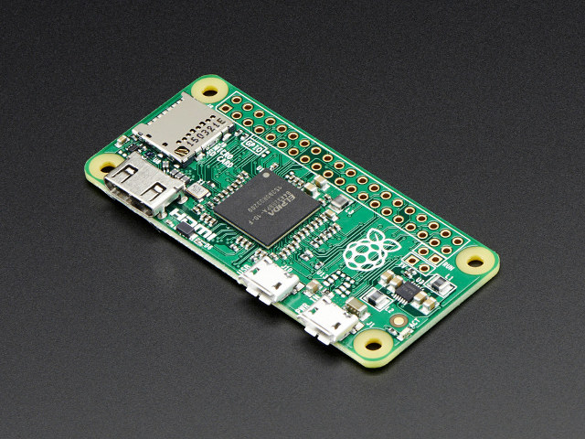
Raspberry_Pi_Zero.jpg

Announced a new Raspberry:

Today, I’m pleased to be able to announce the immediate availability of Raspberry Pi Zero, made in Wales and priced at just $5. Zero is a full-fledged member of the Raspberry Pi family, featuring:

  • A Broadcom BCM2835 application processor
    • 1GHz ARM11 core (40% faster than Raspberry Pi 1)
  • 512MB of LPDDR2 SDRAM
  • A micro-SD card slot
  • A mini-HDMI socket for 1080p60 video output
  • Micro-USB sockets for data and power
  • An unpopulated 40-pin GPIO header
    • Identical pinout to Model A+/B+/2B
  • An unpopulated composite video header
  • Our smallest ever form factor, at 65mm x 30mm x 5mm

With this, shields like the PXF 2.0, NavIO, Raspilot and the one from VirtualRobotix may have a way to cut down costs.

Read more…

Introducing the E386 Mapping Drone

3689672414?profile=original

Our goal at Event 38 is to build products that make aerial data collection for mapping as easy as possible. For a while now, our team has been focused on creating a better autonomous landing solution. At the moment, recovery of a fixed-wing drone requires either a large area for autonomous landings or an operator comfortable with taking manual control.

The two biggest concerns with any autonomous landing solution are:

  1. Onboard sensors tend to drift over time. If there’s a barometric pressure change during a long flight, the drone will develop a discrepancy between its measured altitude and the true altitude above ground level.

  2. A descending drone picks up a lot of speed as it dives toward the ground, but slow speeds are desirable for safety and soft landings.

After much research, development and testing, our engineering team has built a solution that enables a drone to descend rapidly while minimizing forward speed and flaring precisely before impact for a soft landing every time. This makes autonomous landings possible in extremely confined areas, surrounded by tall trees or other obstacles.

Today I’m very excited to share with the DIY Drones Community that this capability is available in our new E386 mapping drone, available as of today! The E386 has a fully customized landing algorithm which incorporates precision laser altimeter data with the ability to fully reverse the motor’s thrust. See it in action below.

Descent gradients as high as 60% are possible when landing with a headwind. The overall size of clear space needed to land the E386 is just 65 x 25 meters. The E386 knows exactly where the ground is and exactly where it needs to flare, every time. Precision flaring not only protects the E386 body from impact damage, but it allows the E386 to touch down as soon as it achieves a safe speed.

3689672343?profile=original

The E386’s landing setup procedure is completely streamlined and only requires you to define the landing runway’s beginning and end points. Mission Planner then shows you where the E386 may touch down given various wind conditions, as well as its minimum projected altitude along its dive slope.

3689672436?profile=original

The E386 also comes complete with a full year subscription to the Drone Data Management System™ Professional Tier. The Drone Data Management System™ is a cloud-based set of tools that store, analyze and share data collected by any drone. DDMS™ automatically creates a geotagged orthomosaic and tiles large maps to be viewed quickly in Map Viewer, our online map tool. The entire processing workflow is automated from geotagging to DEM, NDVI, DVI and more analyses.

DIY Drones members who want to add reverse thrust landing to their planes will soon be able to! We're currently working on generalizing our dive algorithm to work with other aircraft. Once it’s ready, we’ll submit it to be included in the master ArduPlane codebase - special thanks to Tom Pittenger for his help on this! We'll also post a tutorial here about setting up the parameters as well as hardware and operational recommendations. We plan to continue to iterate on this technique to improve landing accuracy and to make the updates available to E386 and ArduPlane users as they become available.


Questions and feedback welcomed! Feel free to leave a message in the comments or to tweet me @mJeffTaylor.


Thanks!

Jeff

Read more…

LightWare announces Black Friday deals

3689672727?profile=original

LightWare is delighted to announce their participation in Black Friday 2015, with significant discounts offered on selected laser rangefinder products. 

You can look forward to the following deals:

  • OSLRF-01 (9m) proximity sensor                   – 20% discount
  • SF02/F (50 m) proximity sensor                     – 20% discount
  • SF30/B (50 m) accelerated UAV altimeter     – 20% discount
  • SF30/C (100 m) accelerated UAV altimeter   – 30% discount

These deals are available to all our customers across the globe, but only while stocks last.

It is valid from 26 November 2015 17:00 EST until 27 November 2015 24:00 EST.

Discounts do not apply to shipping fees.


LightWare wishes all their USA customers a happy Thanksgiving.

Please visit our website for more information: www.lightware.co.za

Read more…
3D Robotics

3689672239?profile=original

This is very encouraging:

ADS-B is an air traffic surveillance technology that enables aircraft to be accurately tracked by air traffic controllers and other pilots without the need for conventional radar.

This article explains how to attach and configure a MAVLink based ADS-B receiver by uAvionix called PING™. Please visit their website for technical specs including RF characteristics and connector pinout.

Read more…
3D Robotics

3689672396?profile=originalFrom the 3DR blog:

Comprehensive GoPro control has arrived in the Solo App! In addition to other feature improvements, version 1.3 brings you in-flight access to GoPro camera settings. In the last release (1.2.1) you got the ability to toggle between standard video mode (shoot up to 4k w/ HERO 4 Black) and photo mode. Now you can use your Solo App to adjust the below settings on your HERO 4 Black (click here for HERO 4 Silver specs; here for Hero3+ Black), while you’re flying.

In coming weeks we’ll release more new features for your Solo, including incorporating industry-first safe flight zone information from AirMap. You can learn more about that here. Other cool features soon to follow. Promise: You will say whoa.

To have the new functionality of this latest app update, you need to update both the Solo App and the Solo firmware. App updates are available on the App Store and Google Play, depending on your mobile platform, and the Solo firmware can be updated through the app. You can confirm that you’re using the latest versions right in the Solo App. Just go to settings -> system info.

Here’s the App store link (iOS).

Here’s the Google Play link (Android).

GoPro settings:

  1. Video Resolution: Choose from a number of resolution options, including 4K, 2.7k, and 1080p
  2. Photo Resolution: Shoot up to 12 MP stills, with the option to select different resolutions. Different resolutions produce different detail and different file sizes: higher resolution gets you higher detail, but generally bigger file sizes.
  3. Auto Low-Light Mode: Your GoPro will automatically change ISO to account for lower light shooting scenarios.
  4. Protune on/off: Toggle GoPro’s protune feature.
  5. Video Frame-rate: Adjust how many frames your GoPro captures per second. Useful because different frame rates give your video different feels: 24fps or 30fps are what you’re used to seeing on film; 60fps is good for action; and 120fps allows you to transform your footage into slow-mo.
  6. Video Field of View: Choose between a wide, medium or narrow frame

Combined, the three main camera settings — resolution, frame-rate and field of view — determine the fundamental look and feel of your video. Here’s what we mean:

When you shoot 4K (best resolution quality) at 30 fps, you can only shoot with a wide field of view. These settings allow you to capture the most of the world around you.

However, we recommend using these settings to optimize your Solo video: 2.7k @ 60 fps in medium FOV. This setting makes your aerials feel more fluid (because an increased frame rate has smoother look) and, unlike shooting 4k, 2.7k allows you to shoot in a medium field of view, for perfectly justified video.

Shooting in 1080p is great for slo-mo, because in this mode you can shoot at 120 fps, which allows you to slow frames down in post and capture dynamic action moments in slow-mo.


OTHER UPDATES IN 1.3

  • Improved the tracking performance and smoothness of the Follow Smart Shot
  • Smart Return Home: Solo won’t climb as high to return if it’s close to home. Solo will always climb a minimum of 2.5m. Click here for a full explanation of how this works.
  • Tuned vehicle flight performance for smoother footage
  • Solo will not enter Return Home due to battery failsafe if it is already in Land mode
  • Sharper white LEDs
  • New sound when Solo powers off
  • Refined stick control
  • Reduced haptic feedback on the controller
  • More clear alert for low controller battery
  • Solo can now take pictures through the Tower app – useful for taking pictures in certain locations for mapping applications

Note: PAL support available in coming update.

Read more…

Affordable RTK Capable GPS Receiver

We are pleased to announce availability of NS-HP, a $50 RTK-capable high performance GPS receiver. At 2 / 4 / 5 / 8 / 10 / 20 / 25 / 40 / 50 Hz update rate, NS-HP is a high-performance GPS receiver suitable for traditional GPS applications. At 1Hz update rate, NS-HP can accept RTCM 3.x message type 1002, 1004, 1005, and 1006, or SkyTraq raw measurement data from a base station to perform carrier phase RTK processing, achieving centimeter-level accuracy relative positioning.

When set to base mode, NS-HP output GPS carrier phase raw measurement data, the base antenna location can be set using binary command or can be self-surveyed.

Below figure show road test RTK performance of NS-HP driving on a road with clear view of the sky, back and forth on the inner lane 3 times, each time using one of three different antennas placed at the same location on the roof of a car. The antennas used are Harxon HX-CSX601A survey grade antenna, Tallysman TW2710, and a low-cost tri-band antenna. The baseline varies from 1.6Km to 2.5Km. Each color represents testing done using a different antenna. Although we tried to keep the vehicle on center of the lane, it’s not easy driving manually; the figure shows variation less than 40cm driving on the same road 9 times.

3689673417?profile=original

3689673463?profile=original

Below shows result using a popular brand normal GPS/GLONASS receiver; as expected the variation is much greater than an RTK receiver.

3689673435?profile=original

Static test scatter plot of 5 minutes RTK fix solution w.r.t. baseline is shown below; with centimeter-level precision.

3689673484?profile=original

Minimum hardware connections needed for NS-HP are:

UART1 TX1:    to output NMEA result

UART2 RX2:    to input base station data (not needed for non-RTK use)

VCC33:            3.3V power

GND:                ground

RFIN:                connect to GPS antenna

3689673380?profile=original

Using a Bluetooth serial module (2.1 EDR) connecting to TX1 and RX2, running NTRIP client software (Lefebure) on Internet-connected Android smartphone, setting smartphone Developer Options to allow mock locations enabling use of external GPS, one can immediately upgrade their Android smartphone GPS with high-precision RTK capability, one step toward "The Democratization of Accuracy (http://blogs.esri.com/esri/esri-insider/2015/09/03/the-democratization-of-accuracy/)”, an interesting blog by Brent Jones. Mobile GIS data collection on Android smartphone using cloud-based software (http://www.terragotech.com/products/terrago-edge/gps-receivers) would be possible.


Connecting RX2 to wireless radio to receive base station data, the NS-HP TX1 NMEA output can be used for outdoor precision machine control in the fields.


For base station data, it can come from public/private RTK base station within 10Km retrieved using a NTRIP client, public/private RTK base station that provide virtual base station (VBS) service then distance can be relaxed, or using another locally placed NS-HP in base mode.


The only catch with NS-HP is that, it’s GPS-only, time to RTK fix (TTRF) can vary w.r.t. GPS satellite availability and orientation as below figures show. We in Asia see many GPS + BDS satellites combined, TTRF is consistently much shorter with GPS/BDS RTK receiver. For GPS/BDS RTK receiver users in the US, due to currently very few BDS satellites visible, GPS/BDS RTK will behave like GPS-only RTK; users will see performance improvement over the years as more BDS satellites are put into orbit from 2016 ~ 2020, until BDS becomes fully operational in 2020.

3689673509?profile=original

3689673555?profile=original

3689673602?profile=original

3689673542?profile=original

NS-HP uses carrier phase measurement to achieve centimeter-level accuracy. Compared to normal GPS receiver, NS-HP is much less resistant to noise, noise level that normal GPS still function reasonably well the NS-HP likely will not able to get RTK fix but will have float or single solution, giving similar accuracy as a normal GPS receiver. Thus for UAV application, unless hardware could be redesigned with shielding to minimize noise radiation, ad hoc method might be needed to get NS-HP to work on a UAV (including placing antenna at different location, using RF absorber, changing board-level module to other brands that doesn’t interfere...).


Other known issues with NS-HP for RTK applications are:
1. Single-frequency RTK works within 10Km baseline
2. Operate only under open sky
3. Require 6 or more satellites above 15degree elevation angle with good satellite geometry
4. Require signal over 38dB/Hz


NS-HP is available for pre-order on the NavSpark website. First batch of 50pcs pilot production ships out on December 15.


Thank you for your interest!

Oliver

Read more…

BBRover Off Road

We have finished up the BBRover, BBCopter and BBPlane.  I also created a YouTube channel for BoxBotix.  Hope to go live with small Kickstarter next weekend.  Yes, yet another drone Kickstarter.

There are plenty of pics/videos of stuff flying so thought we would see how the BBRover does off-road.  And it actually surprised me a bit.  Does pretty well with the 12in "Big Wheel" mod for not having suspension.  We have decide to start with a bit smaller wheels (8in diameter) for the first kits as the little planetary gear motors don't like the big wheels and really hard abuse.  The warning about stalling a gear motor and causing gear damage is no lie.  Still think we have a good Rover design to start for indoor/outdoor use.  We will plan to go full on Monster Truck with larger gear motors a bit down the road.  Then need to figure out best way to integrate payload and sensors.  But that is why we will open source it all.  Hope to start dropping initial files this week.  

R,

C

Read more…

Multirotors are underactuated, thus controlling interaction with the environment such as aerial manipulation has some problems. However, although these problem can be addressed using multi-DOF actuators or some novel control techniques, multirotors suffer from short flight time and limited payloads.

The video below uses a spherical joint to connect multiple quadrotors to the structure and use each quadrotor as rotating thrust generator.

This way the quadrotors may benefit both in flight time and payload capacity while maintaining the agility of the quadrotor. Some groups have also used tethers to use multiple quadrotors on a single aerial platform.

I am interested in implementing this system using the APM flight stack to fly outdoors. However, it seems that APM does not support attitude control on ROS. Curious why px4 supports attitude set point topics but not APM.

Read more…
3D Robotics

COMING SOON - Quanum i8 APM/PixHawk radio system

--------------------------------------

COMING SOON - Quanum i8 APM/PixHawk radio system

The Quanum i8 Radio was developed specifically for APM/PixHawk users. The dial has pre-set PWM positions that can be assigned by the user via Mission Planner software. Along with 2 sliders for gimbal control and 8 channels in total the Quanum i8 is a groundbreaking radio and the first radio system in the market developed specifically for Ardupilot users. The included receiver is also said to have simultaneous PWM and PPM output! Each position on the dial is indicated by one of the 6 LEDs on the top of the radio, a set of stickers to suit your mode selections will be included with each radio to customize your setup.

http://www.hobbyking.com/hobbyking/store/__90960__COMING_SOON_Quanu...

(reposted from this discussion)

Read more…

3D modelling with Pix4D or AutoDesk reCap 360

Midas-Aniti-Yazilikaya-Eskisehir-01-1024x672.jpg

Hello,
 
I want to share my experience with 3d modelling an archaeological structure called "Midas Monument" located at Yazılıkaya, Turkey. It was relatively an easy task, if you have right hardware and software. And I want to thank to dronmarket.com for the encouragement and give-away a RTF drone.

I started with taking photographs, of course your Images need to be processed with GPS data on Images' EXIF. About 9 min. flight allowed me to take 180 photos at interval of every 3 seconds. It was a free flight, not an autonomous, I knew the basic rules, so I tried to keep focusing on structure and flying in circle. You can find basic information on Ardupilot's Wiki

3bset-1024x536.png


As I mentioned taking 180 photos took 9 mins. Then I went to home to process the Images, Pix4D was my first try. 

Ekran-Al%C4%B1nt%C4%B1s%C4%B12-e1447666589521.png
It analyzes all the Images and creates point cloud.

Ekran-Al%C4%B1nt%C4%B1s%C4%B14-e1447666665435.png

Using Pix4D feels like using other CAD programs, its relatively easy.
Proccessing took 8 hours on my computer, its a Dual Core PC with an old ATI graphics card. Pix4D also offers cloud rendering which is nice if you have an old computer like mine.
Finaly, texture is added and now we can render a HD video. We need to add camera positions.

Ekran-Al%C4%B1nt%C4%B1s%C4%B1-e1447666703795.png

This is the rendered video.

And this is Sketchfab model which I exported from reCap360.

Images from AutoDesk reCap360, completely cloud rendered but limited to 50 photos if you don't have a subscription. 

Midas360.png

3b.png

Read more…

3689672141?profile=original

Having received many positive emails about my Extended Kalman Filter Tutorial, I wanted to see whether I could write my own general-purpose EKF from scratch, suitable for running on a microcontroller like Arduino, Teensy, and the STM32 platform used on today's popular flight controllers (Pixhawk, Naze, CC3D).  I wanted something that could be easily modified as new sensors were added, but that didn't use dynamic memory allocation or other techniques that are impractical in an embedded environment.

The result is TinyEKF, a C/C++ EKF implementation that takes care of most of the EKF algorithm for you.  There is a C++ version for Arduino/Teensy, and a pure C version for STM32.  For both versions, you use #define to specify the number of state values N and the number of sensor measurements M.  You also provide a method to compute the output of the state-transition function f(x), the observation function h(x), and their respective Jacobian matrices F(x) and H(x).  As you'll see from the examples, this involves perhaps ten lines of code for each implementation.  TinyEKF takes care of the rest (prediction, update).  This implementation is naturally not as efficient as the hard-coded EKFs you see in actual flight controllers, but I am hoping that with today's increasingly fast ARM processors, and perhaps some behind-the-scenes optimizations, TinyEKF will become a useful, scaleable way of implementing your own EKF.

I've provided an Arduino example using sensor fusion of a BMP180 barometer / temperature sensor with an LM35 temperature sensor. For those who don't have an Arduino but want to try it out anyway, there's also a GPS example in C, using realistic satellite data stored in a .CSV spreadsheet.  Once I get my STM32 Nucleo board, I plan to  port the Arduino sensor fusion example to that platform as well.

Read more…

Density and Total Air Temperature

HeaderPhoto.jpg

NOTE : Experimental. To avoid formulas visualization issues we've setup a free Newsletter. Once subscribed you will receive a pdf with the article. http://www.basicairdata.eu/newsletter.html

Air density \(\rho\) is a common case of measurement derived from air data. Let's investigate the relationship between air temperature and air density, which, incidentally, is the base of the external air temperature measurement in moving vehicles.

Commonly the air density can be calculated with an equation of state or with an interpolated best-fit curve. In both cases, we have to deal with an equation of the form \(\rho=f(T,p,RH, others)\). Let's make things a bit simpler and start with a simple relationship between density and temperature:

$$\rho=f(T,Constant)$$

Temperature in the SI is measured in degrees Kelvin, but many equations of state may also be given with temperature expressed in \(Celsius=Kelvin – 273.15\). Quoted from BIMP: "The kelvin, unit of thermodynamic temperature, is the fraction 1/273.16 of the thermodynamic temperature of the triple point of water.". The thermodynamic temperature is correlated to the state of a thermodynamic system and according to the third law of thermodynamics it defines an absolute temperature scale. For dry air, the ideal gas equation of state is

$$\rho=\frac{p}{R_{specific}T}$$

where

\(\rho\) is the air density in \(kg/m^3\),

\(p\) is the absolute pressure in \(Pa\),

\(T\) is the absolute temperature in \(K\) and

\(R_{specific}=287.058\frac{J}{kgK}\) is the specific gas constant for air.

The main advantage of the equation of state is that it provides a closed form solution, which in turn can be incorporated in other computations. This is a very convenient property for analysis purposes. Let's proceed with a density calculation. Refer to figure 1; our idealized test setup is a room with two thermometers and a fan. The first thermometer measures the temperature of the air in the room at a point far away from the fan effects, while the second one is subject to the direct airflow from the fan.

figure%2B1.png

Figure 1: Example layout

Prior to any calculation let's introduce the stagnation temperature, which indicates the temperature at a stagnation point within a flow field. At the stagnation point the local flow velocity is zero. We find a stagnation point on a Pitot tube tip or in a total air temperature probe.

In our example, the air from the fan which hits the thermometer is brought to rest on the surface of the sensing element. Consider an infinitesimal volume of the overall air stream traveling at a certain speed. This small volume has a corresponding kinetic and gravitational potential energy. If we assume that this volume does not exchange any form of energy with the surroundings then this energy must be converted when one of its forms is eliminated. In the process where the air slows down, kinetic energy is converted into heat, which causes a temperature rise. Assuming an adiabatic process we can describe the enthalpy at stagnation

$$h_s=h+\frac{V^2}{2}$$

where the enthalpy term \(h\) is that of the nearest point along the streamline and

\(V\) is the speed of the air flow.

For an ideal gas it holds that

$$h=u+pv$$

where \(v\) is the specific volume and

\(u\) is the internal energy of the gas.

By manipulating the enthalpy expression and taking into account the constant pressure heat capacity definition \(Cp\) for an ideal gas \(h=C_pT\), we arrive at

$$T_s=T+\frac{V^2}{2C_p}$$

This equation defines how much the temperature rises because of the fact that is adiabatically brought to rest. 

Returning to our example let's calculate the different values of stagnation temperature in correspondence of different airspeed values. You can find pre-calculated values in the table below.

T [K] Static

V [m/s]

V [km/h]

M

T0 [K] Stagnation

Deviation [K]

Deviation [%]

Parameters

288.15

0

0

0

288.15

0

0

Cp

1005

J/Kg/K

288.15

2

7.2

0.01

288.15

0

0

c

340.3

m/s

288.15

3

10.8

0.01

288.15

0

0

288.15

4

14.4

0.01

288.16

-0.01

0

288.15

5

18

0.01

288.16

-0.01

0

288.15

6

21.6

0.02

288.17

-0.02

0.01

288.15

7

25.2

0.02

288.17

-0.02

0.01

288.15

8

28.8

0.02

288.18

-0.03

0.01

288.15

9

32.4

0.03

288.19

-0.04

0.01

288.15

10

36

0.03

288.2

-0.05

0.02

288.15

11

39.6

0.03

288.21

-0.06

0.02

288.15

12

43.2

0.04

288.22

-0.07

0.02

288.15

13

46.8

0.04

288.23

-0.08

0.03

288.15

14

50.4

0.04

288.25

-0.1

0.03

288.15

15

54

0.04 

288.26

-0.11

0.04

288.15

16

57.6

0.05

288.28

-0.13

0.04

288.15

17

61.2

0.05

288.29

-0.14

0.05

288.15

18

64.8

0.05

288.31

-0.16

0.06

288.15

19

68.4

0.06

288.33

-0.18

0.06

288.15

20

72

0.06

288.35

-0.2

0.07

288.15

21

75.6

0.06

288.37

-0.22

0.08

288.15

22

79.2

0.06

288.39

-0.24

0.08

288.15

23

82.8

0.07

288.41

-0.26

0.09

288.15

24

86.4

0.07

288.44

-0.29

0.1

288.15

25

90

0.07

288.46

-0.31

0.11

288.15

26

93.6

0.08

288.49

-0.34

0.12

288.15

27

97.2

0.08

288.51

-0.36

0.13

288.15

28

100.8

0.08

288.54

-0.39

0.14

288.15

29

104.4

0.09

288.57

-0.42

0.15

288.15

30

108

0.09

288.6

-0.45

0.16

288.15

31

111.6

0.09

288.63

-0.48

0.17

288.15

32

115.2

0.09

288.66

-0.51

0.18

288.15

33

118.8

0.1

288.69

-0.54

0.19

288.15

34

122.4

0.1

288.73

-0.58

0.2

288.15

35

126

0.1

288.76

-0.61

0.21

288.15

36

129.6

0.11

288.79

-0.64

0.22

288.15

37

133.2

0.11

288.83

-0.68

0.24

288.15

38

136.8

0.11

288.87

-0.72

0.25

288.15

39

140.4

0.11

288.91

-0.76

0.26

288.15

40

144

0.12

288.95

-0.8

0.28

288.15

41

147.6

0.12

288.99

-0.84

0.29

288.15

42

151.2

0.12

289.03

-0.88

0.3

288.15

43

154.8

0.13

289.07

-0.92

0.32

288.15

44

158.4

0.13

289.11

-0.96

0.33

288.15

45

162

0.13

289.16

-1.01

0.35

288.15

46

165.6

0.14

289.2

-1.05

0.37

288.15

47

169.2

0.14

289.25

-1.1

0.38

288.15

48

172.8

0.14

289.3

-1.15

0.4

288.15

49

176.4

0.14

289.34

-1.19

0.41

288.15

50

180

0.15

289.39

-1.24

0.43

288.15

51

183.6

0.15

289.44

-1.29

0.45

288.15

52

187.2

0.15

289.5

-1.35

0.47

288.15

53

190.8

0.16

289.55

-1.4

0.48

288.15

54

194.4

0.16

289.6

-1.45

0.5

288.15

55

198

0.16

289.65

-1.5

0.52

Table 1. Stagnation temperature vs static temperature at different V values. Download spreadsheet.

By inspection of the table, the deviation between the two temperature measurements increases with the air speed.

The air density in the room should be calculated using the static temperature, in our case, for e.g. \(p=101325 Pa\) the corresponding density is \(\rho=1.225\ kg/m^3\). The same calculation using the total temperature with a fan pushing the air at 55 m/s gives \(\rho=1.218\ kg/m^3\), which is about a 0.5% of error on density.

Inspect the relationship between static and total temperature for a total air temperature probe; the first formula in this link.

$$T_{total}/T_s=1+\frac{\gamma-1}{2}M^2$$

where the “total” subscript indicates the adiabatic temperature and “s” subscript is for the static temperature. This formula is in accordance with our example formula. To reach this formula from our derived temperature equation, substitute in this formula the definition of the specific heat ratio \(\gamma=C_p/C_v\), the Mayer's relation \(C_p – C_v = R\) and the Mach number expression \(M=V/\sqrt{\gamma R_{specific}T}\).

The total air temperature computed up to now here is somewhat ideal. All the kinetic energy is converted and contributes to a temperature rise but it should be accounted with an appropriate recovery factor (Commercial example here, equation 3). The relationship of the recovery factor with airspeed and other environmental factors is not trivial and for best accuracy it should be experimentally found. Nonetheless, the tight relationship between airspeed and temperature can be exploited to have a true air speed indication as per equation 9 in the previous link. Consequently, a total air temperature probe working together with a Pitot-static tube offers a useful redundant airspeed indication.

Even at low airspeeds, to achieve top performance, the temperature measurement rise due to airspeed is existent. However, the impact of this effect on temperature measurements can be neglected in many applications with moderate to no loss of accuracy. Unfortunately, this is not the only source of uncertainty in a total air temperature probe. There are other aspects that hinder much more the performance of the total air temperature probes. Thermal aspects will be considered in a following article.

Further reading

General description

Full developed calculation example

Read more…
Developer

DIY Linux autopilot - cool for cats... and geeks

3689672193?profile=original

I want to share with you the tremendous fun I'm having with the BBBmini DIY ArduPilot project, which I discovered during the summer. Hopefully, I can demonstrate what a sexy DIY Linux Autopilot for around 100 bucks looks like and convince you why Linux autopilots are cooler than a cat playing the piano.
 
For some background, Mirko Denecke, who designed the BBBmini, wrote an introductory blog post on his DIY ArduPilot Cape here, and about further enhancements here.
 
Since Mirko released rev1.4 into the wild as Open Hardware, there's been a BBBmini usergroup down at DIY Drones, so that's a good place to see what's happening with the technology.
 
Rekindled enthusiasm
 
Being a Linux autopilot enthusiast, I naturally had a BeagleBone Black lying around and so was immediately attracted to this project. While building and getting the BBBmini into the air, I quickly realized that it was just the right kind of project I needed to rekindle my enthusiasm.
 
DIY Linux autopilots: What's the attraction?
 
I really love the idea of flying Linux autopilots and must admit I've been hooked since I saw the first talks Andrew Tridgell and others gave on the topic, the early rumors about PXF, and the first boards like NavIO and  Erlebrain and so forth. I can see a bright future in this field, with the kind of  collaborative community effort such as that down at DIY Drones - which drives the technology forward.
 
After finally joining the Linux autopilot club, I had a kind of epiphany about how it opens a huge door to the opportunity of getting new ideas integrated much more easily thanks to the power of open innovation. The underlying Linux offers a sense of comfort and massive gains in usability.
 
Getting more out of your Autopilot
 
For example, I recently decided to configure my quad to log into different folders each day and rsync my log files to my NAS running samba at startup. That way I can archive them for later use as well and delete old logs when the SD cards becomes full. So, I should be find logs more easily and create a permanent archive, which was the initial reason for the set-up. This was all done with a few very basic modifications and open source tools / software made available by developers for public use.
 
Build your own DIY Linux autopilot
 
So, if you too like getting hands-on and want to make your own DIY Linux autopilot, now is the time to get your feet wet.
 
We're all keen to see what you'll come up with. For example, Mirko did a self-balancing robot based on the BBBmini and ArduPilot software, and I have something in the pipeline to fill the long winter nights.
 
We are working on improving the BBBmini experience and since Mirko recently added dual-MPU9250 support we are now flying with two MPU9250's. We also have a few ideas for extra add-ons.
 
I have put together a BBBmini DIY Kit to simplify the process of getting started, and if you are interested in buying a kit or just a PCB please send me a PM or go here.
 
Here is a short video of me flying the bbbmini just for fun.


The full project is available on GitHub and we invite interested users to contribute to the further development of the project.
 
Happy flying.
 
Cheers,
Linus
 

Read more…

3689672029?profile=original

We are proud to announce the release of a new major version of UgCS – 2.6.

The new version features many important improvements over previous versions. The main highlights are:

- You can now plan and execute missions in UgCS with DJI Phantom 3 and Inspire 1 by using UgCS desktop version together with our Android app “UgCS for DJI” available on Google Play

- Geotagging feature is now available in UgCS! Select your pictures and the telemetry data will automatically be added.

- Click and go function is now implemented. This works for the newest DJI vehicles – Phantom 3, Inspire 1, Phantom 2 Vision+ as well as 3DR vehicles using APM or Pixhawk autopilots.

- UgCS Pro now supports two new professional autopilots – Kestrel and Micropilot

Another important change we have made is that all UgCS One versions are now combined. This means that you no longer need to buy a One version for a specific autopilot. UgCS One now works with all autopilots with the exception of professional autopilots – Kestrel, Micropilot and Microdrones, which are exclusive to UgCS Pro.


Important to note is that UgCS is not using Google Earth API. As you may have heard, in December DJI will discontinue support for their PC ground station software due to it being reliant on Google Earth API. This means that UgCS will become almost the only desktop mission planning solution for DJI drones.

For more information and downloads visit our site: www.ugcs.com

Safe flights,

UgCS Team

Read more…