A very interesting and thought provoking explanation of why the conventional wisdom of elliptical lift distribution needs rethinking. Interesting for lovers of fixed-wing but also might be applicable for propellers and rotors...?
All Posts (11086)
Sort by
Here it is! Finally, the PixHawk Fire Cape (PXF) is ready for a wider audience and we've launched a crowdfunding campaign so that everyone can get theirs. We've been iterating through different generations over the last year and with the help of many, we are finally proud to announce the PXF starting at $100.
This board was born out Philip's hands and pushed by members of this community so it's just reasonable to try making it as affordable and accesible as possible. Some technical details:
Sensors
- MPU6000: 3-axis gyroscope, 3-axis accelerometer and temperature sensor.
- MPU9250: 3-axis gyroscope, 3-axis accelerometer, 3-axis magnetometer and temperature sensor
- LSM9DS0: 3-axis gyroscope, 3-axis accelerometer, 3-axis magnetometer and temperature sensor.
- MS5611-01BA03: Barometer that includes pressure and temperature sensors.
Connectors
- 3x LED indicators (Green, Amber and Blue)
- 2x serial UART ports (ttyO0 is not active)
- 1x CAN connector and transceiver
- 3x I2C ports
- 1x Buzzer
- 1x Safety switch
- 9x PWM output channels
- 1 PPM/S.Bus in
- 1x Spektrum
- 1x Power brick connector
- 1x Battery backup (1 LiPo cell)
- 1x ADC
- 2x GPIOs exposed (IO)
- 1x analogic pressure sensor (AIR)
Mechanical characteristics
- Size: 88.6 x 54.73 x 20.69 mm
- Layers: 6
- PCB Thickness: 1.62 mm
- Weight: 31 grams
Support the crowdfunding campaign of the PXF here.

We’re thrilled to announce the release of DroneKit, an open platform for drone app development. DroneKit packages years of 3DR’s flight control R&D into a single robust and extensible platform which developers can use to create web-based drone apps, or even apps onboard the drones themselves. DroneKit works with any vehicle powered by the APM flight code.
Why now
We want to empower makers anywhere to create apps that fit their purposes. Imagine an agriculture app that surveys your land; a search & rescue app; a football practice app. Before DroneKit, if you wanted to create any of these single-purpose apps for a drone you’d have to reinvent the wheel, building all the flight control software from the ground up. DroneKit abstracts away the hard parts of writing flight control software, leaving you a clean, modern interface to code on.
A good analogy is the smartphone: In order to make a smartphone app, you don’t need to design and create a phone first. The hard part (the platform, in other words) is already done. With DroneKit, we’ve made the phone, so to speak. Now everyone has the creative freedom to build apps and new functions.
“Unlike other APIs for drones, there are no levels of access to DroneKit; it’s completely flexible and open,” noted Brandon Basso, 3DR’s VP of Software Engineering. “The platform works on laptops as well as mobile devices. Best of all, once an app is created, the app automatically works on any computing platform—the interface is always the same.”
Our role is to maintain DroneKit: we created the API; we’ll fix any issues with it; we assure it works with all APM vehicles; we add experimental features from our labs and from those contributed by the global community, and we make all updates available to anyone for free. And should you develop an app, just put it up on 3DR Services, “the app store for drones,” where you can price it how you want, and we won’t take anything off the top. DroneKit is a community garden for technology; we want anyone to be able to use it to cultivate and take their product to market.
What you can do with DroneKit:
With DroneKit, you can develop apps for three platforms: mobile apps (DroneKit Android); web-based apps (DroneKit Cloud); and onboard computer apps (DroneKit Python) [i.e., for a companion computer on the actual drone].
DroneKit allows you to:
- Fly paths with waypoints
- Fly in spline path with fine grain control over vehicle velocity and position
- Have the drone follow a GPS target
- Control the camera and gimbal with regions of interest points
- Access full telemetry from the drone over 3DR Radio, Bluetooth, Wi-Fi, or over the internet
- View playbacks and log analysis of any mission
Advantages of DroneKit:
- Truly open; no “levels” of access that you get from other proprietary programs
- Computer agnostic: Create an app for controlling drones on whatever computing platform you want, and the interface is always the same
- Works on planes, copters and rovers
- Works on laptop computers as well as mobile devices
- Provides web-based access to vehicle data
DroneKit powers the most successful flight control programs in the world:
- Tower (formerly Droidplanner), hands-down the best flight planning mobile app out there, was built on DroneKit for Android
- Droneshare, the global social network for drone pilots, is built on DroneKit web services
- Project Tango Indoor Navigation is built on Pixhawk, APM and Tower
- IMSI/Design TurboSite aerial reporting app for construction
Online Access
To find out how to write your own application for UAVs, and to walk through some example apps from us, please visit http://dronekit.io
Ospheric has just released a beta of its new cloud-based flight planning service, which allows you to import paths from Maya, Collada, Autodesk and Google Earth and export them as APM waypoint files. As Ospheric's Jon Farat explains:
The idea is to use 3D environments to create flight plans for VFX shots involving CG set extensions, and repeatable aerial camera moves.The purpose of this project is to create a professional planner that exports WP files for use in all GCSs.
It's due out of beta on April 30th. Looks like a great start!
Interesting coaxial design coming from Ascent Aerosystems. In general coaxial designs have limited speed and maneuverability, but for the "aerial selfie" application this is designed for, that may be fine. I don't see a stabilizing gimbal, so I imagine this is mostly for still photos. Very portable and robust-looking design, however!
From Droneblog:
Tell us about yourself and a bit of your personal background.
Nate & Jon: We’re both aerospace engineers by education, fans of cool new technology by habit and small UAV designers by choice and by passion. We also happen to be twin brothers by genetics. We’re originally from the Boston area but we moved to the Phoenix area about 5 years ago.
Peter: I’m an incurable nut for everything that flies. I was one of those kids who always wanted to fly airplanes for a living, and I did that for about ten years. I made a switch to a more traditional business career in 2001.
We discussed how none of the conventional multirotors available at the time could be realistically brought along on a hike, climb or mountain bike ride.
What made you want to start Ascent AeroSystems?
Nate: Jon and I are avid outdoor enthusiasts, and a few years ago we were out rock climbing in Prescott, Arizona when we came across a situation where we really could have used an overhead view to help find a trail. On the walk back to the car we discussed how none of the conventional multirotors available at the time could be realistically brought along on a hike, climb or mountain bike ride. They’d be cumbersome, get in the way, and they just aren’t rugged enough. So being engineers, we started working on our own design. After literally dozens of tries over about two years, we finally got to a configuration that gave us a consistent, stable hover and good controllability. We started to circulate the concept on a few blogs dedicated to drone enthusiasts, and the level of interest expressed from all corners of the globe within just a few days blew us away. We thought maybe we were on to something. Along the way we had gotten to know Peter. He was familiar with the UAV business space and challenged us to really explore what we could do with the design. He’s tapped into what people want and expect from a product like this. Together we decided that we’d make a great team to bring the concept to market. In the time since, we’ve done a lot to develop the vehicle’s features, and we’re convinced we have the best aerial technology platform available anywhere.
What kind of experience have you had with UAV’s prior to this?
Nate: Jon and I flew RC planes when we were younger and as part of a design team in college, but we generally missed out on a lot of the early quadcopters. I think this is why we were quick to consider other configurations. We didn’t approach the design from “how to we make a quad rugged and portable.” It was obvious that kind of vehicle just wasn’t going to be. It was kind of like the old Henry Ford story…”if you would have asked people how to improve travel in the early 1900s, they would have designed a faster horse.”
Peter: I’ve been an avid RC builder and flier since…I forget when. Maybe 1980? Something like that. I’ve done quite a bit with fixed wing model airplanes, but I started flying RC helicopters with a model called the Cricket in the 1980s. I moved on to others over the years I always appreciated those that were really rugged. I only got my first quadcopter in early 2014, and I have a few in my workshop right now.
Please describe your UAV and your goal with it.
Ascent offers an unmanned aerial platform that’s unlike any other. Instead of four, six or even eight propellers spinning on the end of extended arms, our vehicles are coaxial designs with two stacked rotors spinning on a cylindrical airframe.
Everything is packed neatly and securely into that cylinder
and with rotor blades that automatically fold, it’s the most portable and most durable small unmanned aerial systems available. We believe that it is the ideal solution for active outdoor enthusiasts, professionals and commercial operators who are in need an aerial imaging platform that’s easy to transport and reliable enough to fly from even the most remote, rugged locations. We think it’s going to become the standard for UAV systems that are being put to serious work.
What sort of safety features will it have?
We’ve got a number of safety features that will help reduce risk to the operator and to the environment in which the vehicle is flying. We’ll be rolling out details as part of our product launch, and we’re committed to incorporating additional capabilities as they become available.
Who is this UAV intended for? Your target audience.
We have a number of designs in development, but the initial model is going to appeal to people who want a high-quality sensor platform that can be easily packed into a backpack and taken anywhere. It’s a tool, not a toy. For the outdoor enthusiast, it can shoot great “follow me” video footage while on a hike through the countryside, or it can go into the backcountry and take a beating. It’s water-resistant and it even floats, so water enthusiasts will be able to do things that up until now they could only dream about. Components like rotor blades can be changed in seconds, and larger components can be removed and replaced without tools. For the professional or commercial operator, time is money. They need a platform that can take knocks and dings and keep on going. This will be the system that they’ll be able to put to work, reliably, day after day. The modular design will make upgrades easy.


Read the rest here
We have added new functionality to UgCS. Integration with DroneShare to ease sharing and "bookkeeping" of your flights.
In this article we are going to show you how to fly a mission in UgCS, replay the mission in the telemetry player in UgCS and then upload the telemetry from the mission to Droneshare.
1. Open UgCS and add your vehicle
2. Create a mission and process the created route
3. Upload the route to the vehicle
4. Fly the mission
5. Open telemetry player
6. Add your vehicle and navigate to the timeframe when the flight took place
7. Replay your mission if necessary
8. Open the Upload to Droneshare window
9. Enter your Droneshare credentials and click OK to upload the mission to Droneshare
10. That’s it, your mission has been successfully uploaded to Droneshare! Click the link to view the Mission on Droneshare
Enjoy!
UgCS Team
Hi Everyone,
Good news for small drones, New FLIR Lepton 25° camera cores just arrived.
If you have read this post before , I have tested our new camera design with 50° version of Lepton and the range was shorter than 50 meters for human body because of wide angle lens design and low resolution of Lepton.
So we ordered 25° FOV FLIR Lepton modules to DroneThermal cameras instead of 50°.
These new cores are fully compatible with current developer boards and other Lepton based designs.
I tested it and zoom factor is exactly 2 times higher than the previous one.(test video coming)
DroneThermal analog thermal cameras will come with these new cores. We are waiting for PCB manufacturing now then I will share final product details and features.
You can find more details and photos under the product page.
Thank you for reading.
Melih
(representative DIY version shown, not Google's)
"Google’s quest to introduce small unmanned aircraft systems (UAS) into low altitude airspace within a “few years” has driven the company to launch an unexpected foray into the avionics market, says Dave Vos, head of the Internet company’s Project Wing.
Two companies – L-3 Aviation Products and FreeFlight – have recently unveiled automatic dependent surveillance-broadcast (ADS-B) transceivers for general aviation priced under $2,000, hoping to entice aircraft owners to install the mandated precision-locating equipment.
Google’s unmanned aviation venture now plans to beat that price and produce thousands of ultra-low-cost ADS-B Out transceivers for the manned and unmanned aviation market, Vos said 23 March at the Remotely Piloted Aircraft Summit hosted by the International Civil Aviation Organization (ICAO).
“We think that – and we are going to do this – we will head-down the trajectory of putting into the marketplace really, really low-cost ADS-B solutions,” Vos told the ICAO audience.
Asked in an interview later if that meant beating the $2,000 threshold, Vos indicated that was possible.
“We have to answer the question: What does the market find palatable in order to really transform? And that’s where we’re going,” Vos says. “Think about it: Would you spend $2,000? We have to make it happen.”
Driving Google’s strategy is a fundamental obstacle to its plan of launching a UAS-based drone delivery service in a few years. Google’s unmanned vehicles need to operate in airspace below 500ft that is currently used by tens of thousands of general aviation aircraft. Some of those aircraft owners have been reluctant to spend money to equip their aircraft with an ADS-B Out system.
Google is also looking deeper at software algorithms for traffic collision avoidance systems, says Vos, a former executive at Rockwell Collins. If Google’s vision is realised, the skies above urban centers could be filled without thousands of ADS-B-equipped UAVs. That could overwhelm current pilot displays showing potential collision threats.
“We think there are some good solutions to make it not so cumbersome,” Vos says.
Those efforts are part of Google’s effort to be “respectful” to manned aircraft using the airspace today, he says. As an internet company, Google is used to fixing software bugs after rolling out new products for customers. That culture had to be changed after Vos arrived at Project Wing, he says.
“Really bad things happen if there is a bug and we didn’t figure it out,” Vos says. “We don’t just get to stop and check under the hood when we’re flying things. I’m super, super-excited to say the team at Project Wing has pretty much done a 180 in only about 3-4 months and really has embraced the [aviation] culture.”
From Flight Global:http://www.flightglobal.com/news/articles/google-targets-low-cost-ads-b-out-avionics-market-410473/
I want to introduce the BBBMINI.
BBBMINI is for people who want to build a Linux autopilot based on ArduPilot themselves. BBBMINI is based on a BeagleBone Black connected to a MPU-9250 IMU and a MS5611 barometer. Both the IMU and barometer sensor can be purchased ready soldered on a breakout board by many manufacturers.
Objectives of the project:
- DIY project, build a Linux autopilot based on ArduPilot with a minimum of hardware
- no SMD soldering required
- DIY friendly 2.54 mm pin header to connect external hardware (other can also be used)
- connection to ground station via (wireless) LAN, or other telemetry radio
- easy start to develop ArduPilot for Linux
- inexpensive
First successful test flight already done.
BBBMINI is already a build target in the ArduPilot master branch:
https://github.com/diydrones/ardupilot
ArduPilot for Linux is experimental, so please take care, it comes with absolutely no warranty.
For more information please check:
Great news from the FAA, and part of an encouraging trend towards a much more progressive regulatory process in the US:
The Federal Aviation Administration has established an interim policy to speed up airspace authorizations for certain commercial unmanned aircraft (UAS) operators who obtain Section 333 exemptions. The new policy helps bridge the gap between the past process, which evaluated every UAS operation individually, and future operations after we publish a final version of the proposed small UAS rule.
Under the new policy, the FAA will grant a Certificate of Waiver or Authorization (COA) for flights at or below 200 feet to any UAS operator with a Section 333 exemption for aircraft that weigh less than 55 pounds, operate during daytime Visual Flight Rules (VFR) conditions, operate within visual line of sight (VLOS) of the pilots, and stay certain distances away from airports or heliports:
- 5 nautical miles (NM) from an airport having an operational control tower; or
- 3 NM from an airport with a published instrument flight procedure, but not an operational tower; or
- 2 NM from an airport without a published instrument flight procedure or an operational tower; or
- 2 NM from a heliport with a published instrument flight procedure
The “blanket” 200-foot COA allows flights anywhere in the country except restricted airspace and other areas, such as major cities, where the FAA prohibits UAS operations. Previously, an operator had to apply for and receive a COA for a particular block of airspace, a process that can take 60 days. The agency expects the new policy will allow companies and individuals who want to use UAS within these limitations to start flying much more quickly than before.
Section 333 exemption holders will automatically receive a “blanket” 200 foot COA. For new exemption holders, the FAA will issue a COA at the time the exemption is approved. Anyone who wants to fly outside the blanket parameters must obtain a separate COA specific to the airspace required for that operation.
Erle Robotics continue working towards improving ROS support and creating packages that people can use to build applications.
APMCopter and ROS (roscore and mavros) is running on Erle-Brain. Through mavros someone can have control of the autopilot from ROS. Also it's possible to see how the values are changing in APM Planner.
The following shows a simple interface where is possible to visualize the flight mode and the state of the drone (armed or disarmed). It's possible to change the state of the flight mode using the comboBox. The code is available in github[1]
Also it's possible to override the radio control, the virtual joysticks are configure in mode 2 (left joystick: throttle and yaw,right: pitch and roll).
In the following video we explain how to use a color filter to control a quadcopter. In the first part of the video It explains how to tune the color filter in a color and in the second part how the controller is working, the controller can change throttle, pitch and roll. The code is available in github[2].
We'd love to hear your opinion about which ROS abstractions you'd like to see in Erle-Brain.
Regards,
[1] Source Code: https://github.com/erlerobot/ros_erle_teleoperation
[2] Source Code: https://github.com/erlerobot/ros_erle_computervision_teleoperation
If European regulators have their way, drone operations in the European Union (EU) are going to become very permissive, far outpacing American regulations. The European Aviation Safety Agency (EASA), the EU’s authority for aviation safety, has released a regulatory framework that calls for new regulations to be proposed by December of this year.
In their proposed framework, the EASA has specifically focused on innovation, saying that regulations must “not simply [transpose] the system put in place for manned aviation” but rather must create “one that is proportionate, progressive, risk based and…[expresses] objectives that will be complemented by industry standards.”
Read more here http://www.forbes.com/sites/gregorymcneal/2015/03/23/european-drone-regulations-are-about-to-get-smarter-and-more-permissive/
Best regards
JL

Drones may take advantage in more than one way of the virtual reality buzz. Valve announced its Lighthouse positional tracking solution along with the HTC Vive, and more details are emerging about the inner working of the system. You can see above the tracking station. The two inner cylinders are rotating and project a horizontal and vertical laser line across the room. The LEDs visible on the PCB are probably for the synchronization signal.
With IR detectors on an object, is is possible to determine the position of the object using precise timing and trigonometry. Valve claims sub millimeter accuracy. The tracking station is dumb, meaning that it only projects the laser lines at a precise interval. You could add a few IR detectors on a drone and with the right interrupt based algorithm, even a 25$ Multiwii board running on the Atmega32u4 could position accurately a drone within a given space.
For drones, it means:
- Very low processing cost (simple trigonometry, can be done on board)
- Unlimited number of markers and object tracked
- Cheap hardware (consumer level prices)
- Limited tracking (15m by 15m)
I think it is exciting news for research labs and enthusiasts. The system could provide the same level of accuracy as the $25k+ camera tracking systems. It will speed up development until full ultra precise embedded SLAM is available. I am looking forward to see the first reverse engineering post about the device protocol! Micro drones will navigate precisely inside a house.


Hobbyking has done it again and have gone that step further.
500mw telemetry modules for amp/px4 and pixhawk is a reality.
Features:
• Interchangeable air and ground 433MHz modules
• Micro-USB port
• 6-position Molex connector
• 500 mW maximum output power (adjustable)
• -117 dBm receive sensitivity
• SMA connector
• 2-way full-duplex communication through adaptive TDM
• UART interface
• Transparent serial link
• MAVLink protocol framing
• Frequency Hopping Spread Spectrum (FHSS)
• Configurable duty cycle
• Error correction corrects up to 25% of bit errors
• Open-source SIK firmware
• Configurable through *Mission Planner and *APM Planner
Specs:
Supply voltage: 3.7-6 VDC (from USB or Molex connector)
Transmit current: 500 mA at 27 dBm
Receive current: 25 mA
Serial interface: 3.3 V UART
Included
Two radio modules with antennas
Micro-USB cable
Android OTG adapter cable
6-wire Pixhawk connector cable
6-to-5-position APM and PX4 connector cable
Self-adhesive patch

The UAV Challenge Medical Express rules have been released.
The Mission for 2016:
"Outback Joe is at his property in remote Queensland, Australia and has been feeling unwell. He has had a remote consultation with his doctor using video conferencing, and his doctor has requested some blood tests be done as soon as possible. Joe is well prepared, has a home sample taking kit, and has taken his blood sample. The challenge is now to get the blood sample to the lab. Joe’s property is very remote and to make matters worse, it has been cut off by floodwaters.
Teams are invited to attempt to retrieve a blood sample from the remote Outback Joe and return it to base where medical staff will be waiting to analyse it. Teams must deploy unmanned aircraft to Joe’s location, and then return a sample bottle from him utilising a remote landing and takeoff site close to him. They must complete all of this within one hour."
Documentation can be found here:
Rules PDF here: https://docs.google.com/file/d/0B5JgqjkRDqw8dTllN085ZTJyNjQ/edit
Site: http://uavchallenge.org/medical-express/
Challenge FAQ: http://uavchallenge.org/medical-express/medical-express-faq/
Brief overview of the 2016 OBC rules:
- Two aircraft are allowed that can detach/reattach to eachother > one as retrieval aircraft and one for support > both can be airborne at the same time
- Range required +40km but no more than 60km through "bent" geofenced transit corridor - waypoints will likely backtrack to get the total distance, but will be at least 250m apart. (see FAQ)
- Flight must not take longer than one hour so the airframe must be able to achieve roughly 90-100kmh average, as well as be VTOL or STOL (!)
- The RF Link range required is approximately 10km (3-4G Mobile and Satellite comms allowed - safety case req. for landing zone etc)
- 1500ft AGL altitude restriction
- 25knot average wind over 10 minutes will cancel the event (which is higher than last time)
- Joe GPS coordinates that are provided are within 100m of Joe. One must locate him and land no closer than 30m, but no further away from Joe than 80m - distance away is scored at 2 points per meter - Joe has lost his colorful shirt but kept his jean pants on - phew!
- payload to be picked up is 20x100mm and no more than 100g and must be returned intact back to base.
- aircraft must remain motionless for 1 minute after landing near Joe before Joe will approach to place payload - Takeoff Arm switch is required by Joe at pickup location with one minute takeoff delay after activation
- Biggest points are for delivering intact sample back to base
- Only the top 20 ranking teams through D1-D3 will get to go (based on paperwork, flight logs and videos) - That will be tough
- Might not be at Kingaroy this time...
No specifics are given to the makeup of the Joe takeoff landing site or base site, apart from that it will "impede low glideslope landings". So this could allow something like a Skywalker X8 with a quadcopter strapped underneath to launch and fly to location, identify and locate Joe exactly, then detach the quad for payload retrieval, while the X8 stays above the landing zone as RF relay until quad is released to takeoff, then both can head back with the X8 arriving first and possibly landing with a parachute and then the quad with payload some minutes later. A single VTOL might be nice but you'd have to land/takeoff blind without RF link. Helicopters welcome.
Shouldn't be too hard.... I think I have the gear for that here already. Time to dig out old Tinker Bell and send her back to get Joe! ;-)
Hi Diydrones Community,
We just started to develop flight monitoring app for smart watches, We are aiming to have important features like when battery is critic watch will vibrate and warn the user, on the other hand drone pilots can voice command to change flight modes over watch(this will be hard to develop, we will do our best). Of course flight critical information can be also monitored on the watch.
We will add artificial horizon, however; this may not be useful since we can see the artificial horizon over phone, may be drone pilots wants this as a dedicated artificial horizon. We will also include a professional compass, barometer, and altimeter functions.
Currently we already developed a free app called CompassX for android wear smart watches, i think it will be very handy at the field for now. Let us know what you think and what you want?
Thanks.
From National Geographic:
A variety of platforms and quadcopters have recently come my way to test, fly and review. I base my reviews on my knowledge of Unmanned Aerial Vehicles (UAVs), which combines practical experience from frequent travels around the world with National Geographic Expeditions and a strong personal interest in the civil applications of quadcopters and other UAVs. The essential tools in my camera bag are upgraded phantoms by DSLR pros, but I am always happy to experiment.
It is important to understand that no machine is perfect, and as artists and creators, we should get out of our comfort zone to improve.
In recent weeks I have enjoyed flying a stylish blue machine. I have started testing an Iris+. I meant to write this article weeks ago, but I felt I could provide a more accurate and objective feedback, if I had experimented with this machine for a while.
My first step was to gather as much information as possible. This drone is developed by an American company, 3DRobotics. After a little research and some flying, one must agree that Iris+ has a very advanced autopilot system, boasting autonomous missions, and GPS assisted flight.
As I recommended on my article “So You Want to Fly Drones?”, I believe you should have at least some flying experience before purchasing an Iris+. But this is just common sense. Flying, like everything else in life, is a process. So the better informed and the more practice you have, the more likely you are to have a quick and appropriate response any circumstances.
The Iris was co-developed by Chris Anderson, who was the editor-in-chief of WIRED Magazine until 2012. In October 2007, Anderson flew a remote-controlled aircraft equipped with a camera over Lawrence Berkeley National Laboratory, which ended up crashing into a tree. Despite a bit of a rough landing, this experience inspired him to co-found 3D Robotics, a robotics manufacturing company which was a spin-off of the website DIYdrones.com. Today, 3D Robotics produces the Ardupilot series of autopilots, which are based on the Arduino platform.
I see this wonderful machine as a great tool for creators and hobbysts, with the ability to customize it, and with many different types of settings. Some cool features include:
Follow Me technology: If you own any GPS-enabled Android device, you will be able to activate the Follow Me function. The drone will be able to follow the GPS signal and keep the camera centered on you, capturing dramatic, targeted footage. So those who wished for a personal cameraman are in luck. The quadcopter locks on you and follows you down your trail or whatever adventure you may be immersed in, as long as you tote a GPS-enabled device. Obviously, at least for now, it will not avoid trees or other objects in the way.
Stability in the air: The Iris+ has exceptional stabilization capability, helping you capture sharp photographs and smooth, balanced films.
Auto Mission Planning: This amazing feature lets you preplan a flight path for the Iris+ from the ground using the Mission Planning application. It’s as easy as taking out your tablet or touch-screen phone, and tracing the path out on a map, that is configuring the waypoints and flight path beforehand. The drone will take off and go exactly where you tell it to. It will follow the path that you set out for it and come back with perfectly sequenced footage, without you having to steer it at all.
Flight Protection: If the Iris+ is running out of battery, it can land itself automatically, or return to a set home point. Your camera and drone will be well protected from falls.
‘Geofence': Before taking off, you can set boundaries for the flight. If you end up running into one of these boundaries, the Iris will automatically return to its launch point.
LiveView: The 3DRobotics Kit for GoPro includes everything you need to start live streaming a video feed from the GoPro on your IRIS+ or X8+. It is easy to install, even for non-handy photographers like myself. With no tools, it will probably take you ten minutes to put it together. It comes with a 7-inch monitor and a 5.8 GHz 32-channel wireless receiver.
Interview with 3DRobotics Flight Specialist Anton Plauche
from my upcoming book on drones:
“When looking into FPV monitors a monitor that ‘blue screens’ is one of the first things people will tell you to avoid,” said 3DRobotics Post-Production Manager and Flight Specialist Anton Plauche.“This is common in many monitors that accept digital signals where the signal coming in is clean and as long as the signal strength stays above a certain threshold. But if the signal drops below that threshold the video will cut out entirely and you are left with a blank blue screen. The monitor supplied in 3DR’s video feed kit on the other hand handles your downlink as an analog video feed, meaning that the monitor will continue to display the video feed no matter how weak the signal is, even if it is completely static” explains Plauche.“You can imagine this is very advantageous when flying FPV, for instance if your copter flies beyond trees or encounters a source of interference. Even if your signal is knocked down to 90% static you can still make out landmarks in the video feed and safely pilot the copter back,” added Plauchet. Whereas with a monitor that ‘bluescreens’, flying beyond range results in a total loss of signal and can be dangerous as well as result in a loss of equipment.”
“An interesting feature this kit has is that the monitor allows two channels to work simultaneously. One example of when dual video feeds can be useful is when operating a multi rotor with a 3 axis camera gimbal attached, allowing the camera to be pointed in any direction independent from the multi-rotor,” said Plauche. “In this case a small camera can be placed on the front of the craft for the pilot to view, in addition to a feed from the camera attached to the gimbal so that if the main camera is pointed straight down, for instance, the pilot can still see what is in front of him through his piloting cam.”
It is easy to see that this quadcopter brings to the table all those things that the previous Iris 1.0. didn’t have, plus much more. But it should be remarked that the new Iris runs on the new innovative advanced autopilot system called Pixhawk. Designed by the PX4 open-hardware project and manufactured by 3D Robotics. It features advanced processor and sensor technology from ST Microelectronics® and a NuttX real-time operating system, delivering incredible performance, flexibility, and reliability for controlling any autonomous vehicle.
The benefits of the Pixhawk system include integrated multithreading, a Unix/Linux-like programming environment, completely new autopilot functions such as Lua scripting of missions and flight behavior, and a custom PX4 driver layer ensuring tight timing across all processes. In other words, these advanced capabilities ensure that there are no limitations to your autonomous vehicle.
The flagship Pixhawk module will be accompanied by new peripheral options, including a digital airspeed sensor, support for an external multi-color LED indicator and an external magnetometer. All peripherals are automatically detected and configured.
Did I mention that with the simple switch of a toggle, you can tell your IRIS+ to return to its launch point whenever you see fit?
Many people email me regularly inquiring what is the best quadcopter for me. My answer is that it is your decision to make. As a journalist, my job is to share my field experiences with my readers, so they can make an informed decision of which path to follow in terms of equipment. So if you are looking for a compact and durable platform, an all-in-one autonomous aerial vehicle with the consumer in mind, the Iris might be right for you. The Iris+ comes with everything you need to take off right away.
Follow Kike Calvo on Facebook, Twitter, Web, Tumblr, LinkedIn or Instagram.
Iris+ Basics:
Flight Time: 16-22 min (depends on payload).
Charging Time: 45-60 min. Battery Type: 5100 mAh 3S
Battery Camera: Go Pro Hero 4 or other brands
Maximum Payload: 400 g. payload capacity
Motor-to-motor Dimension: 550 mm. Weight with Battery: 1282 g.Electronics
Autopilot hardware: Next generation 32-bit Pixhawk with Cortex M4 processor
GPS: uBlox GPS with integrated magnetometer
Controller: Any PPM compatible RC unit, Preconfigured FlySky FS-TH9x RC
Telemetry: 3DR Radio 915mHz or 433mHzComponents:
Propellers: (2) 9.5 x 4.5 tiger motor multi-rotor self-tightening counterclockwise rotation,
(2) 9.5 x 4.5 tiger motor multi-rotor self-tightening clockwise rotation
Motors: 950 kV
GPS: uBlox GPS with integrated magnetometer
Mounts: Integrated GoPro camera mount with vibration dampener
Optional: Tarot brushless gimble with custom IRIS+ mounting kit
Battery: 5100 mAh 3S
What’s in the box: Ready-to-Fly IRIS+, Transmitter, 3DR telemetry radio, Micro USB cable, Android OTG cable, Set of tall legs for IRIS+, 5100mAh 3S battery, LiPo charger and a Manual with a flight checklist.


Within this post we will examine a basic design approach for the Kiel probe sizing. This probe is intended for total pressure measurement, necessary for airspeed calculations. From now on we will assume that airspeeds are well below 0.3 times the speed of sound, so it's safe to say that we are not facing any remarkable compressibility effects. Air density is denoted with \(\rho\) and relative airspeed is \(V\).
Let's start with a review of the total pressure probe described in NACA-TN2530, where you can find the section view visible in the following figure. After CFD simulation with the NACA design we will propose and analyze a custom design.
Total pressure \(P_t=P_s+q+\rho gz\) is a sum of three terms. The first term corresponds to the static pressure, the second is the dynamic pressure \(q=\frac{1}{2}\rho V^2\) and the third accounts for gravity effects. If we assume that our flow is adiabatic and incompressible, then in our case the Bernoulli's principle holds quite well and along the streamlines \(V^2/2+gz+P_s/ \rho\ =constant\).

Figure 1. NACA-TN2530 Total Pressure Probe
If we add, only to drop it immediately afterwards, the inviscid flow hypothesis, the total pressure does not depend on the geometry of the probe; every point inside the outer tube has the same total pressure. The probe is composed by two main parts: the external shield and the enclosed total pressure port. In the next figures, in the direction from upstream to downstream, you can see the inlet convergent conical nozzle, the cylindrical throat, the divergent nozzle section and the outlet holes. On the centerline of the inlet nozzle the total pressure tap is situated . The outlet is composed by 24 holes of 6.35mm diameter, with a total outlet area of 7.6e-4 \(m^2\). Inlet area is 5.1e-4 \(m^2\). The outlet section has 50% more area that inlet section, which helps minimize the downstream blockage effects.
Flow is axial, along the major tube axis. The mass is conserved across any section \(i\) of the probe of area \(A_i\) and mass flow rate \(\dot{m}=\rho VA_i\) is constant. Air enters the shield and accelerates until it reaches the maximum speed at the throat, where the minimum cross-section area is found, then decelerates through the divergent exit cone and finally exits the probe radially. Pressure is maximum at the inlet, then decreases to its minimum value at the throat and then the rises progressively up to the divergent section. To evaluate the design performance a CFD approach will be used. In Figure 2 you can find the 3D model of the NACA probe ready to be processed by Salome mesher. The cylindrical section and the trailing cone were added to have a smooth flow stream.
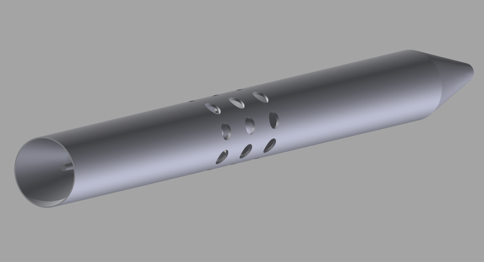
Figure 2a. 3D Model of Probe Under Test, Dimensions from Figure 1

Figure 2b. First-Guess Mesh. Shown to Visualize the Internal Geometry of the Probe.
All the simulations are conducted in a 3D domain, but for better visual representation many results are presented as 2D slices. The intention behind these simulations is to better understand the behavior of the probe under different angles of attack, not to verify the NACA results. In case of doubt, it is better to run the simulation at the same conditions using two or more meshes. Usually a good solution doesn't change with the use of two well-designed meshes.
We simulated the probe with zero angle of attack and we obtained a total pressure value of 101340.1Pa. The actual free-stream total pressure is 101340.6Pa, so at 0 degrees the probe is performing well. Simulation related problems apart, since we don't know some dimensions or details of the NACA probe there will be a certain baseline difference between our results and those of NACA report. It is also worth noting that the magnitude of relative wind for all our simulations is 5 m/s.

Figure 3a Total Pressure Probe at 0 degrees AOA
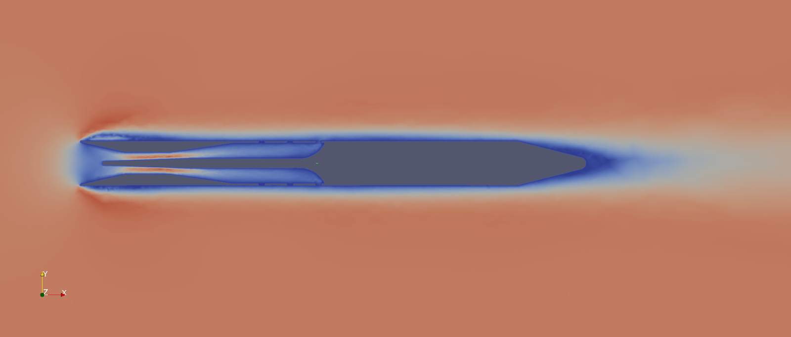
Figure 3b Velocity at 10 degrees AOA

Figure 3c Velocity at 30 degrees AoA. Total Pressure Value at 101340.40Pa

Figure 3d Velocity at 60 degrees AOA. Total Pressure Value = 101329.5Pa. According to definition NACA Error = 0.79
The simulated probe is expected to work well up to about 40 degrees and this behaviour was verified with CFD. Probe measurements started to diverge from their ideal values at 35 degrees. You can find a limited subset of the results depicted in Figure 3.
Now that we are familiar with the probe design, let's address some issues. The position of the pressure tap is not arbitrary and it will have an impact on the probe overall performance. Referring to Figure 3, at high angles of attack a significant wake will appear, which also interacts wit the head of the probe. With that kind of effect in mind, we may prefer placing the pressure tap near the probe throat, in order to mitigate issues at the probe inlet. However, by inspection of table I of reference, "Tube 2-a" and "Tube 2-b" in particular, we see a contradicting indication. The table highlights the fact that, in terms of maximum angle of attack, the probe with the pressure port placed nearest the probe entry is performing better. The stated Mach number for the lab test is 0.26. In such a regime, our initial assumptions do not hold: the flow is compressible (Air flow accelerates inside the convergent section), hence we are reading a table that is not addressing our design approach. The behavior of the Kiel probe at low airspeed will be different, so we should validate by ourselves the pressure tap position impact at low speeds. Consider also the boundary layer, the more you retract the total pressure port inside the shield the more that tap is near the walls.
Another important aspect is the shape of the inlet. The simpler conical geometry seems perform worse, compared to curved inlets. The shape of the inlet modifies the velocity profile and a curved inlet will produce a smoother airspeed transition. With an elliptic nozzle, the area reduction gradient is greater at the inlet and progressively decreases to zero at the throat. In this way, the velocity gradient is kept low when the velocity magnitude is at maximum. For very low airspeed the probe can manifest measurement issues related to the boundary layer. That effect needs a dedicated analysis.
Other aspect to consider is the divergent section length. In this section the pressure should grow from its minimum value to the exit value. The smoother the transition is, the better is the pressure recovery. At the exit cone the air is flowing from a low pressure zone to a high pressure zone, hence separation of flow from the internal wall should be expected. Despite the fact we cannot use the Venturi tubes formulas for prediction of the pressure loss as a function of diverging cone angle, it's possible to observe that proposed angles for diverging cones in various design standards are between 5° and 15°. That range provides a valid initial estimate value for the area gradient in our probe design.
Regarding the exhaust holes, they should be placed in a position that minimizes the internal pressure variation at high angles of attack. It is expected that at high AoA, an airflow will be established between the holes placed upstream and the holes placed downstream and the impact of this flow on probe performance should be investigated.
In this article, we have familiarized with the total pressure probe and highlighted some key design points. In the next article we will proceed to present some results regarding the proposed BAD probe.

Figure 4. Generic Design of BasicAirData probe. Dimensions are not definitive.

This just popped up on a Canadian Commercial Operator Facebook group and we're discussing the implications and legal possibilities. Apparently the operator claims that this has been cleared with Transport Canada, but nobody is sure yet what the details of that are.
This does not appear to fit in with existing commercial regulations. It seems unlikely that a commercial operator would be able to get a permit to fly in a crowded area like a ski hill. I have taken a guess as to what is going on here:
The operator is not operating the drone. They are renting drones to recreational users. Not much different than selling drones to recreational users. The user is the pilot in command, not a commercial operator. The user captures images of himself. Then the operator edits the footage. It would bypass all of the commercial regulations. Some disagree that this would be legally possible, but I don't see why it would not.
Currently, a person can rent a Uhaul truck, without being required to possess a commercial truck license. And I think it would be over-reaching if the government tried to stop a person from paying somebody to edit footage for them, no matter how it was captured.
The key to the whole gambit, is the drone rental, and the Follow-Me device is pivotal for that to work in this case. Some of the marketing material show a Phantom, but the video from Cape Productions clearly shows a 3DRobotics X8.
No matter how this situation is being managed, it presents a very interesting legal scenario, that could test some of the implications of the existing Canadian UAV Regulations.
Aeroquad with pixhawk,3dr radios,3dr gps/mag,teensey 3.1 for telemetry to taranis.Using 3.2 firmware with stock pid's.I completed 4 autonomous missions using mission planner(GCS) and all 4 were flawless!Love the aeroquad setup.picture attached.
