All Posts (11086)

Sort by

Hello All, I had the great pleasure on having Trent from MyGeekShow as a guest on the DIYDrones Vodcast. Here we talked about his mission of flying over USA as well as the hurdles he had to overcome to be in the position he is today with knowledge and experience of his drones.

Enjoy.

Christiaan

Read more…
3D Robotics

Send your cool drone videos to MAKE

3689568297?profile=original

From Make:

Next Tuesday, Jan. 21, we release Volume 37—the “homegrown drones” issue. The magazine will be filled with profiles, projects, and stories about maker friendly multicopters. As part of our coverage online we want to see how and where the maker community is flying their drones. If you’ve got video footage of your drone in action please sent it to me at sholbrook[at]makermedia[dot]com. Please put “drone video” in the subject line. I’ll be assembling the best user submitted videos in a post next week.

I put out a call for videos last year and got some great stuff. Have a look.

And if you’re in the neighborhood, we’re hosting a drone fly-in Jan. 20 in American Canyon, Calif. Fly on over!

Read more…
3D Robotics

3689568285?profile=original

I agree! From The Verge:

In today's Senate drone hearing, Senator Dianne Feinstein (D-CA) got personal, describing a rally held outside her home earlier this year. "I went to the window to peek out, and there was a drone right there looking in. Obviously the drone's pilot was surprised, because the drone wheeled around and crashed," she told the Senate Committee on Commerce, Science, and Transportation. "What kind of camera was on the drone? What kind of microphone? Could an enterprising person have attached a firearm to it?"

The hearing mostly concerned with the FAA's roadmap for regulating civilian drone use, spurred on by Amazon's recent announcement of a drone delivery program. But Senator Feinstein used her time to specifically speak out specifically against the prospect of private citizens equipping drones with deadly force, potentially opening the door for a new legislative avenue regulating the unmanned crafts. "We should not allow armed drones in the United States, period," the Senator told the committee. "It should be a crime for a private individual to arm a drone."

Read more…
Moderator

UCmulti.jpg?width=400

“Drones have gotten a very bad rap for various reasons,” says Kelly Cohen, associate professor of aerospace engineering and engineering mechanics at UC. “But our students see that unmanned systems can have a positive impact on society.”

Cohen and a team of researchers have developed an experimental capability to capture the dynamic behavior of the UAV platform, which complements other work they’ve done with UAVs in disaster management operations. Wei Wei, one of Cohen’s students and the lead author of “Frequency-Domain System Identification and Simulation of a Quadrotor Controller,” will present the UAV dynamics research Jan. 16 at the American Institute of Aeronautics and Astronautics’ SciTech 2014 conference in National Harbor, Md. The event unites international aerospace scholars and professionals to collaborate on advances in research, development and technology.

http://www.uc.edu/news/NR.aspx?id=19101

Read more…

CAD Drones Design Challenge Contest Giveaway!

3689568239?profile=original

What's up Diy Drones?!  It's Joshua Johnson from CAD Drones with a Gimbal Design Contest for all you CAD and Drone Junkies!  To View the CAD Challenge page you can visit: http://caddrones.com/cad-challenge 

CAD CHALLENGE CONTEST RULES AND INFO:

  • Submit all Contest Gimbal Designs to the DataBase under the category CAD Challenge Submissions
  • Your design must use/fit servos with the Dimension: 40.6 x 19.8 x 37.8 mm
  • The Gimbal Contest Design File Submissions must be in .stl form
  • All Designs must be submitted by February 14th
  • Whom ever makes the best design will win 4 1000 kv out runner brush less motors and receive a special prize that will be made "Public Information" closer to the end of the contest
  • It must NOT exceed 130mm square
  • Your submission(s) can NOT be a modified version of any open license, or paid license design. It must be original!

CHALLENGE SPONSORED BY SENCORP

**We are looking for strong/robust designs!**

Take it easy Diy Drones,

Joshua Johnson

Read more…

DIY $100 FPV Micro Quad

Hi, I *finally* got round to recording video on my homemade fpv system. The quad is a WLToys V929:

3689568150?profile=original


3689567846?profile=original


3689567996?profile=original

I wrote a blog about how to build it here: http://dalybulge.blogspot.co.uk/

Basically, I make the Video transmitter like this:

3689568156?profile=original

Then the receiver is done like this:

3689568217?profile=original

I also made my own FPV Transmitter tray holder:

3689568268?profile=original

The Video came out OK, but I'm still learning how to fly (basically I suck at steering the quad right now)

I'm also attempting to build a tiny OSD to display altitude data and flight time. It's an ongoing project, but would love some input and feedback: http://benbojanglesosd.blogspot.co.uk/


Thanks for reading.

Read more…
Moderator

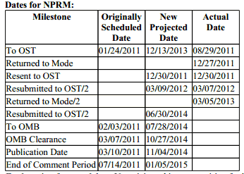
DOT delays NPRM yet again.

FAA.jpg

This post is dull and only of interest to those in the USA. But if you are in the USA and want to fly commercially it should have your full attention.

The start of the rule making process that you have all been waiting on is pushed back to November of this year, maybe.

Not the first time this has happened, sUAS News has a count down timer which is in negative numbers from one of the previous dates two years ago.

NPRM-dates.png

http://www.suasnews.com/2014/01/26979/dot-delays-nprm-until-nov-2014/

Read more…
3D Robotics

MAKE hosts a drone fly-in

3689568119?profile=original

First cool thing: ArduCopter is on the cover of the new MAKE magazine, which is all about drones! Second, they're hosting a drones fly-in:

This coming Tuesday we are excited to release Volume 37 of the magazine. The issue, which is the first of our larger, six-times-a-year format, is all about “homegrown drones”—maker friendly, DIY multicopters.

As with each issue release we’ll be hosting an international maker meetup. But instead of holding the event indoors, this time we’re stretching our wings with a drone fly-in event Monday, Jan. 20 from 1-4pm at Paintball Jungle in America Canyon, Calif.

Join MAKE editors, up-and-coming drone companies and startups, and local user drone groups for a day of aerial fun. Bring your friends, families, and drones for this one-of-a-kind event. RSVP right here.

MAKE will provide food and refreshment, copies of the MAKE drone issue, and cool MAKE swag. See you there!

Read more…
Developer


During the alpha testing phase with the "APM Copter V3" code
i immediately reported to the Dev Team that the Loiter mode was very accurate but is not allowed to fly normally, like with other system as DJI and Mikrokopter, Zero-UAV, etc.
We preferred to make the Loiter mode that would serve to accurately reposition the multirotor, and to help beginners to fly slowly and safely.
An italian friend and developer, Sandro Tognana, collected my challenge and started to develop a flight mode as I wanted, in line with the other famous flight control board.
Another awesome programmer, Julien Dubois, has joined our team and has worked actively to implement the complicated wind compensation.
After several months of development and testing are pleased to present the "Hybrid flight mode", in two words a "flyable Loiter" with wind compensation, the code virtually switches from "Loiter" to "Alt-Hold" and viceversa when you exit and enter a sticks deadband (configurable), considering of course the compensation of the wind, therefore complies with the tuning of your multirotor.
You can configure some parameters but already with the default works perfectly, my video speaks for itself.

This new mode is currently being debugged (in alpha phase), it is therefore not available to the public, of course, will have to go into the hands of APM Copter Dev Team who will decide whether to adopt it in an upcoming release.
The results in my video are great, sorry but the audio is bad because it was very windy today, however, is clearly seen as a "Hybrid" works, is almost perfect.
In the second video by Julien you can see the Hybrid in action vs a "DJI Phantom 2" quad with "Naza 2" inside, imho Hybrid work better than the "GPS Position Hold" of DJI, especially on braking.
The tests were carried out on APM and VR Brain, but of course will work on any board that installs "APM Copter" as PX4 and Pixhawk.
I will keep you updated on the "Hybrid" developments, i'll open a discussion about this with other APM Copter developers to assess any changes in the code.

I want to say thanks to Sandro and Julien for their great work!

Bests, Marco

Read more…

For DIY Drones newbies (and non-newbies)

3689567889?profile=original

Welcome to a remarkable, international, and evolving community. I was a newbie/noobie/noob to DIY Drones in 2012. I found much useful information while reading over 2000 DIY Drones blog posts during 2013. Some links to those blog posts have been collected on THIS page. 

Newbies: Add your suggestions to other newbies below on this DIY Drones blog post. You may want to include suggested links to other useful information. Please avoid turning this blog post into a discussion or debate, and remember the Terms of Service.

Non-newbies: This is an opportunity to give back to the DIY Drones community.

Happy searching!

Read more…

Variable pitch central motor quad copter

3689568017?profile=original


I have a long history of being involved with R/C planes and helicopters and moving into drones is a natural extension of that. However, until recently I had little exposure to quad copters and I had the opportunity to see them fly at a drone meet. I got interested in them and decided to build my own instead of buying something off the shelf. The goal for the project was to develop a central motor variable pitch quad copter. The purpose of the variable pitch is to increase the flight envelope which allows things such as inverted flight as well as faster response to things like wind. The benefits of this were well documented in the work that MIT did and a video of some of that can be seen here http://youtu.be/VIkqqVr_u9U. The second portion of this project is to centralize the motor. The purpose of this is to get the heavy motor off of the ends of the quad to further reduce inertia and increase response rate. It also allows the user to gear down the motor to swing a larger prop at slower RPM. This increases the total prop area and reduces the disc loading which makes the quad more efficient. It is also my hope that the mechanical systems will be lighter than the motor/ESC setup which will reduce the overall weight. The downside to all of this is the added mechanical complexity and increased cost of components.


The design effort started with a traditional X configuration with a central spur gear that ran the power to pulleys. This design did work but it was REALLY noisy and had so many gears that it robbed efficiency. The support blocks were made from 3D printed nylon which I had done at shapeways. The gears were RC car parts and the variable pitch system was from a small RC plane system. I used an APM for the flight controller. This is version 1 and it can be seen flying here https://www.youtube.com/watch?v=ZrD4gScApQk.


3689567958?profile=original    


A lot was learned from this design and we quickly moved to version 2 which is nearing completion. Version 2 features a more efficient and much quieter drive train as well as a V-tail configuration. The official reason for the V-tail configuration is that it has better yaw control but secretly the reason is that it just looks cool! 


3689568017?profile=original3689568045?profile=original3689568060?profile=original


Read more…

3689567798?profile=original

Hello All,

It is that time again where we have another diydrones vodcast on Google hangouts (diydronestv@gmail.com) and in this episode I am glad to have Trent from MyGeekShow on my next vodcast episode.

We will be airing live on our Google Plus Page on Wednesday 15 January 17:30 GMT.

Please join us and listen to Trent's story and his adventures on MyGeekShow where we will find out where it all began and all of the stepping stones he had to overcome to be where he is today.

The interview will be on our YouTube channel for you to watch over and over.

Hope to see all there.

3689567827?profile=original

3689567749?profile=original

3689567916?profile=original

3689567867?profile=original

3689567933?profile=original

Read more…
Moderator

3689567644?profile=originalThis isn't a build log. And what's shown here wasn't built as a rover. It is a rover, sure, but it was built as a playground, a collection of dozens of separate experiments, trials, and ideas. I build this a few months ago, and I'm about to tear it apart and rebuild it based on the lessons I learned, but before I do that, I figured I'd share a bit. 

This was a relatively low cost build, for me, but it would not be inexpensive to reconstruct. I had many of these parts already, so I'll provide some details, but it isn't really a good idea to repeat this exactly. Even I would not build it like this a second time. 

The chassis is a Ruckus Monster Truck. I've been very happy with it. If you know about RC trucks, no doubt, you'll have lots to criticize with this bottom-end 1/10 scale vehicle, but it works just fine for autonomous roving on semi-broken ground and natural grass lands. If you have a lot of obsticles over 3.5-4" and you might need to upgrade to a crawler or something in 4WD.

I'm using an APM 2.5, a 3DR 5.8 FPV kit, with OSD, a Futaba R6208SB rx, a 3DR telemetry kit, a GoPro camera, and a previous generation 3DR LEA6 v1.1 GPS. Besides the 3D printed parts, I use a few #6 screws from Home Depot of various lengths, a 6-to-individual-6 pin'ed cable for the rx (because it was handy, I normally make custom cables from a kit of parts I got over at Hansen's Hobbies,) one 3 pin servo cable for power and channel 8 to the rx, and a few zip ties. 

I removed the shell and some of the plates provided to hold bits in place. One nice feature I made use of here is the twist wing connectors. They are supposed to hold a plate in place for the battery, but the velco strap holes are sufficient for that so I repurposed these twisting winged items as the way to hold the 3D printed body to the chassis. 

3689567692?profile=original

While you can see screws, these screws are not fixed. They are glued onto the orange 3D body, but they act strictly for alignment for the chassis, as pins. Why use screws? They are cheap and easy to source. A smooth pin would be nicer, but I had screws. 

I left a large space above the battery, allowing the battery to be inserted and removed easily without taking anything apart. The body and chassis fit together like a glove, stay rock solid while driving around, and come apart in seconds, but disconnecting the two servo cables is a bit of a pain. In the future, I might add a socket that causes the servo cables to connect/disconnect just by attacking the body. I suspect the guide pins would pay off even more then.

3689567401?profile=originalThe 3D work was created in Google Sketchup, sliced on KISSlicer, and printed using Printrun (for Mac) on a PolyPrinter in ABS. PolyPrinter is a large build area (9x9x9") rock solid industrial-grade FMD printer creative iteratively by fellow Makers in the Dallas area based on their frustrations with less-reliable and more well-known printers. 

In the center of the lower plate, I experimented with integrating Tastywheat's Onmimac 3DR APM Anti-Vibration mount. It works just fine, and while it makes a nice looking stand-alone mount, I would not integrate it like this again. It is far easier to re-create the essential bits and not have to fix all the curves and intersections. You'll notice various arches and buttresses underneath. All of these printed perfectly, without any support, on my PolyPrinter, and they really add rigidity to the structure. While not shown, I did also add thicker triangular bands on the underside of the large surfaces, to add rigidity and reduce weight. This structure was printed in one go, with no issues, and it fits like a glove. The heated bed and fully enclosed space of the PolyPrinter, no doubt, are critical to printing large ABS components like this without lifting or warping. 

The protrusion on the front/left of the sketchup screenshot is the bottom of a GoPro mount. There were several experiments around the GoPro in this build. In the upper place, I included a springy tab that retains the GoPro when inserted. 

3689567717?profile=original

No tools, no screws, just slide it in from the side.

3689567759?profile=original

When it is fully inserted, the GoPro locks into place, but you can still operate all the controls, access all the ports, buttons, and see the all of the indicators. 

It comes out easily, by pushing up on the tab and pulling it out sideways, but will not come loose while driving around, even under hard driving. The back is also open, allowing for GoPro accessories. 

While this arrangement works well, I would not do it like this again, at least not on a rover. The lens gets far too dusty here in Texas, even with light duty. Because the rover is ground-based, weight is not as critical, so for future ground-based builds I will design around the supplied GoPro protective cases. For aerial systems I now use a variation of this arragement, with extra tolerances for a tiny bit of foam on the contact edges. This helps with vibration and gives a tighter fit overall. 

Another minor, but nice, feature of this build, and easier to do in 3D printing than in transitional plate/cut fabrication can be seen for otherwise "hidden" components like the telemetry module. Measuring out where the TX/RX leds would be situated under the top plate, I sunk the plate down over that area so that it is just ~.25mm thick. 

3689567734?profile=original

This creates an high quality effect similar to the hidden indicators found on Apple laptops. While I print in bright orange while prototyping and for my aerial components, I expect this effect would look even sharper when printed on black or some other dark color. Here is a shot of the top plate just as the 3DR telemetry radio LEDs light up. When it isn't lit, you just see orange, but it is so thin that when the LEDs light up, they stand out in the original LED colors. 

3689567776?profile=original

In future prints, I plan to fit the video and telemetry radios better, such that they do not twist at all when installed, but otherwise I'm very happy with how they work. 

I don't use the power module in this build. The rover chassis is powered on 7.2v 6 cell NiMH battery. To use the power module, I'd probably swap out to one of my in-inventory 3S lipos, but that would lead me to replacing the existing ESC and motor while I'm at it, so I've left it alone for now. 

There are a dozen or so other ideas expressed in this build, but I've hit the limit on embedded/uploaded images in a blog post, so I'll call this the end for now. My dialog is boring enough with the images, I will not subject anyone to my text sans photos. Happy hacking.

Read more…

Autotune:0...Ground:2

3689567378?profile=originalMy first official foray into 3.1 has not gone well, and so far, Gravity - and his mistress, the hard frozen ground - are winning 2:Nil.

Both bird were flying fine on 3.0.1. There have been no physical changes. The Disco even flew ok on 3.1, pre-autotune, although I still can't seem to find the source of the vibes.

The Disco started autotune no problem, and you could physically see roll getting tighter and tighter. Pitched started, and that looked good too. I was getting excited. Right up the moment it totally flipped out of control, Belly bounced off the tarmac, and proceeded to freak out some more and self-destructing. Logs are attached, and apart from less than satisfactory vibes, no idea why it freaked out. All physical connections were tight even after the crash, and there were no loose screws or bolts. The new 3.1 engine readings look weird btw...something in there, maybe?2014-01-12%2008-25.log2014-01-12%2008-25.log.gpx

3689567595?profile=original

So I moved onto the quad, which was even more bizzare. It tried to do a fly away the moment I flicked autotune. So I flicked out, but it now went into failsafe RTL. Broke RTL into loiter, and it freaked out again. Realising this was not a route to safe flight, I went back to stabilise, and discovered I had lost all yaw control. Then I made a mistake - instead of just putting it straight down in stablise, I flicked manual RTL, and boom - all motors stop. Stabilise again, but I was too late. Wish I had the logs for that one, but I think the logs are corrupted - it fails at the same point very shortly after starting the download. As mentioned - It was running sweet in 3.0.1...Compassmot: 0%, Vibes well within +/-5, etc. Only thing changed was the upgrade to 3.1.

2 freakouts in Autotuine on 2 aircraft in the same morning session. Both were flying well previously. Methinks I'll stick to the manual PID method, until my confidence is restored...

Amazingly, both are now phyisically repaired already. Disco ready to fly, and I'm doing a ground up, factory-fresh install on the Quad. The fog has come though, so visibility down to 20m. I had a lot of flight activity planned, but it ended up being a frustrating - and short - weekend's flying :-(

Read more…
Moderator

MOU between the FAA and AMA

20140111_150223_resized-1024x768.jpg?width=400

Signed at the AMA Expo, Ontario California. DTV is there and will report back!

Memorandum of Understanding between Academy of Model Aeronautics and Federal Aviation Administration

Concerning Operation of Model Aircraft In the National Airspace System

Purpose

This Memorandum of Understanding (MOU) establishes a cooperative working relationship between the Federal Aviation Administration (FAA) and the Academy of Model Aeronautics (AMA).

Background

AMA is a nationally recognized, non-profit membership organization that was established in 1936. The organization has provided leadership for an expansive aero-modeling community throughout the United States and its territories. Over time, AMA has developed and maintained a National Model Aircraft Safety Code, which provides guidelines for the safe
operation of model aircraft.

Until 1981, there were no federal guidelines or directives for model aircraft operations. In June of that year, the FAA published an Advisory Circular (AC 91-57) titled “Model Aircraft Operating Standards.” Although not directive in nature, AC 91-57 provided general guidance for the operation of model aircraft.

On February 17, 2012, President Obama signed the Federal Aviation Administration (FAA) Modernization and Reform Act of 2012 (FMRA) (Pub.L.112-95) into law. Within this Act, a special provision for model aircraft was enacted. Section 336 of the FMRA provides a definition of the term “model aircraft”, requirements for operating model aircraft, and reinforces the authority that the FAA possesses to pursue enforcement action against persons operating model aircraft in an unsafe manner. In addition, section 106 and 40103 of Title 49, United States Code provides the authority of the Federal Aviation Administration to prescribe aviation standards and regulate aviation operations in the National Airspace System (NAS).

In addition, in the FMRA, Congress acknowledged the efficacy of community-based safety programming, and specified that if a model aircraft is operated in accordance with a community-based set of safety guidelines and within the programming of a nationwide community-based organization, the FAA may not promulgate any rule or regulation regarding that model aircraft.

This MOU outlines the relationship that will be maintained between the FAA and the AMA.

The AMA and the FAA intend to work together by openly communicating any questions and needs as they arise. Technology and operating environments are always changing, and thus establishing an understanding of the nature of the cooperative working relationship between the two organizations is critical to meet the mission needs of the FAA and the AMA.

Agreements

The Academy of Model Aeronautics agrees to:

 Develop, establish, and maintain a comprehensive safety program to educate and direct its members in how to safely operate model aircraft in the NAS.

 Develop, maintain, and enact appropriate guidelines, procedures, and operating standards for its members responsive to the minimum safety criteria established in PL112-95 and implement the AMA Safety Program to include the PL 112-95 Enactment Standards.

 Maintain the AMA Safety Program by regularly reviewing relevant safety data and updating the program to address any issues that are brought to light by the data.

 Continue to establish appropriate safety guidelines for emergent technologies and novel facets of aero-modeling activity.

 Provide the FAA with an updated copy of the AMA Safety Program whenever substantive changes are made, or upon request.

 Foster a positive and cooperative environment within the aero-modeling community toward the FAA, its employees, and its regulatory structure.

 Serve as a conduit between the aero-modeling community at-large, the hobby industry, and the FAA in order to provide relevant and time-critical aviation safety information to all parties.

 Bring issues and questions to the FAA when matters arise related to model aircraft that could impact the safety of the NAS.

 Maintain Safety Programming documentation on the public section of the AMA website in order to promote safety throughout the entire aero-modeling community, even among non-AMA members.

The Federal Aviation Administration agrees to:

 Review AMA’s Safety Program and advise the Academy on safety issues related to aero-modeling operations within the NAS.

 Educate and inform appropriate FAA field personnel regarding the most current aeromodeling policies, procedures, and operating standards.

 Address model aviation safety and operational issues through the Unmanned Aircraft Systems Integration Office, AFS-80. This office will act as a conduit to other areas of the FAA in order to resolve and address matters of mutual concern and interest.

 Foster a positive and cooperative environment towards model aviation within the agency’s national, regional, district, and local offices.

 Maintain an open line of communication with the AMA to exchange information and provide relevant and/or time critical notices regarding aviation safety and airspace operations.

 Cooperate with the AMA in dealing with and resolving issues of concern to either or both parties.

Effective Dates

It is understood and agreed by the undersigned that the intent of this MOU is to state shared goals and to establish and maintain cooperation toward meeting these shared goals. This MOU does not create any binding obligation on either party. Each party agrees to conduct its representative activities in a coordinated and mutually beneficial manner. The FAA and the AMA will evaluate their respective participation with the terms of this agreement periodically and communicate any issues with the term as soon as they arise.

This MOU will be in effect at the time of the signing and may be terminated at any time by either of the signing authorities or their successors. One party or the other must serve the notice of the termination at least ninety (90) days prior to the effective date of that termination, or in the case of mutual consent, with no prior notice requirement.

Read more…

To view the Original Article Visit:http://techcrunch.com/2014/01/09/martha-stewart-goes-3d-printer-shopping-at-ces-2014/

Posted Jan 9, 2014 by Jordan Crook(@jordanrcrook)

"Interested in 3D printing and smartphone-controlled aerial drones? So is Martha Stewart.

She and I had the pleasure of touring CES 2014′s South Hall, where we checked out Parrot, Form Labs, and MakerBot, among a few other companies.

Martha Stewart, who is a judge in our brand new CES Hardware Battlefield, explained that she’s always curious about innovation and loves learning about how new technology can apply to the lives of everyday people. But more importantly, she’s interested in finding a 3D printer to help prototype new products.

Before visiting the 3D printing section, she and I had a blast checking out Parrot’s latest toys, the Mini Drone wheel-equipped aerial drone and the Sumo camera-equipped Rover.

3689567539?profile=original

Stewart already owns an AR.Drone 2.0, using them to aerially film her various properties as well as monitor her grandchildren when they are swimming in the ocean. The smaller, newer products are more toys than utility products, but they’re fun nonetheless.

But what really caught Martha’s eye was 3D printers, as she’s currently on the market to buy a 3D printer for prototyping her own products.

We visited Formlabs and Makerbot, which recently released three new 3D printers, and it seems that Stewart is most interested in the mamma jamma Z18 industrial printer from MakerBot.

But that’s not the only thing she had to talk about. Apparently she and Bre Pettis are forging deals left and right, working to make a Martha Stewart collection of 3D printable products, as well as a magazine spread of 3D printed Easter gear.

To close out the interview, Martha and I checked out the most entry level 3D printing product I’ve ever come across, the 3Doodler. It’s a glue gun-like pen that let’s you draw out super hot plastic onto paper that forms a 3D doodle. It’s only $99, but Martha wasn’t all that impressed with its accuracy."

Read more…
Developer

APM Planner 2.0 RC2 Update

3689567552?profile=original

Hi,

It's been a busy two weeks over the New Year, adding new features to APM Planner 2.0 and fixing some of the issues raised. The current changes include

  • Better handling of missions with Waypoint 0 being marked as the HOME location
  • Improvements to dataflash log analysis
  • Performance improvements to reduce CPU overhead
  • Extra GPS parameters viewable on the map as a overlay
  • Update to APM:Plane PIDs display
  • Layout corrections to APM:Rover
  • plus many other small fixes

Thanks for all the great feedback, more improvements to come

Download from here http://ardupilot.com/downloads/?category=35

Please ask questions here http://ardupilot.com/forum/viewforum.php?f=82

Please report issues here https://github.com/diydrones/apm_planner/issues

The AP2 Team

Have a great weekend

PS: Next release we will try and add autoupdates as this will be the best way to notify users of new changes

Read more…
3D Robotics

3689567521?profile=originalFrom Poynter.org:

Last Wednesday, The (Spokane, Wash.) Spokesman-Review published a minute-long, aerial video of a local event [screenshot shown above].

On Thursday, Jesse Tinsley, the photographer who used an unmanned camera ship to record the video from 30 feet off the ground, said it was “not illegal, but currently in a gray area.”

Au contraire, said the Federal Aviation Administration on Monday.

“There is no gray area,” said FAA spokesperson Les Dorr.

Hobbyists are allowed to use small, radio-controlled crafts under specific guidelines, but “if you’re using it for any sort of commercial purposes, including journalism, that’s not allowed,” he added.

The FAA generally contacts transgressors and requests them to cease their activities, rather than penalizing them (unless they’re operating aerial vehicles in a reckless manner, in which case sanctions could be meted out).

“Our main goal is to get them to stop,” Dorr said. “Most of the time people are cooperative.”

(Two drone journalism programs received cease-and-desist letters from the FAA in July.)

Acknowledging the confusion about the operation of unmanned aircraft systems, Dorr said that soon-to-be-released FAA guidelines about small crafts should make it “much clearer…what you can do and what you can’t do.”

He also acknowledged the appeal for journalists in using drones to report some stories.

“It’s an attractive technology for journalists, and people would like to be able to use it,” Dorr said. “That said, the FAA is responsible for the safety of the air space. And as much as we’d like to encourage them, we can’t let them do it as long as there are no rules in place.”

Read more…

330-gram Mini Quad Upgrades

3689567334?profile=original

I recently rebuilt my mini quad with a new camera, modified ESCs, custom wiring harness and a few other minor tweaks designed to make it neater and less messy. Initially I had just knocked this frame together a selection parts to make it fly.  Even on the stock KK settings (latest update) it flew reasonably well, however there were a few problems and obvious areas where improvements needed to be made. As can be seen below.

3689567406?profile=original

Here is an account of those improvements, along with a list of relevant parts, and some images and flight video.

FASTENERS

The AQ50D frame was supplied with all metal fasteners and spacers which seemed to be overkill in terms of strength, and an obvious area from which to shed some weight.  18 M3x12mm aluminium frame spacers were replaced with 10mm nylon, 2 M3x15mm aluminium spacers were replaced with 15mm nylon, and the majority of the 32 Stainless Steel fasteners were replaced with nylon.  This exercise, while relatively expensive, reduced the weight of the structure by a significant margin.

RC RECEIVER

The V8R4-II is a tiny little receiver with the very smallest of antennas (it is barely longer than an inch) which obviously limits distance between the element and whatever the receiver is mounted to.  I have had varying success with this receiver depending on the type of airframe I place it on.  For example, it is positioned directly beside the battery (just 12mm away from the battery itself) on my balsawood octocopter and yet the integrity of the link is faultlessly reliable, whereas I have experienced dropouts on this little Carbon Fibre frame (with the flight battery and BEC combination consistent on both airframes) especially then flying in build up (noisy) areas.

Considering the very tiny weight of the receiver module, I decided to address the issue by constructing a custom lead to run between the V8R4-II and the KK board which would also serve as a support to raise it well clear of potential sources of interference and to allow for improved signal propagation.  While it works perfectly, I did perhaps make this link longer than it should be.  I actually have another V8R4-II (which my cat had the audacity to use as a teething aid, but which still functions fine) - so I might stripped it down, remove the pin headers and dump the cardboard case in favour of a heat shrink sleeve in order to create a leaner version.

3689567459?profile=original

KK2.0 BOARD

I had purchased a specific lightweight GPS receiver in preparation to upgrade this frame with an APM however, concerned that it might be a bit too much to try and fit on this tiny little frame, I decided against it.

The top of the KK board was already a cluttered mess, with the previous setup and I wanted to add to the complexity by utilising the onboard voltage monitoring circuit and associated buzzer and also use the KK Board for 5V power distribution.  To solve the problem I used tiny pin connectors, soldering pin sockets onto the bottom to allow stealth connection of battery voltage, buzzer and the 4 signal wires for the ESCs.

3689567474?profile=original

ESCs & BEC

When setting the quad up originally, I chose to isolate the BECs from on another.  I did so by eliminating each BECs ability to bridge at the KK board (although I am aware that this is unnecessary).  I then powered the KK board from the output of ESC#1, my 200mW 5.8 VTX from ESC#2 and the 2.4Ghz FrSky receiver from ESC#3 with ESC#4 pin removed and insulated.

The BECs in the little 6A Turnigy ESCs I am using are tiny SOT-223 linear regulators rated at 800mA, however I found that they struggled to deliver anything like that reliably (regardless of whether powered from a 2S or 3S battery).  Without going into too much detail, I had intermittent problems with video link (horrible blizzard), RC link (drop outs) and with the KK board (mostly the screen would drop out or the board would simply not wake up) - all of which caused by voltage sage, with the IC getting extremely hot.

The solution was to add a separate 3A Hobbywing BEC to the mix, which solved all my problems.

With an alternative 5V solution sorted, the 4 linear regulators were essentially worse than dead weight, as they seemed to also be generating much of the waste heat emanating from the ESCs.  I decided to remove them entirely.  While doing this, I also opted to remove the 100uF caps in order to further simplify the form factor of the ESCs, as well as add a set of tiny female pin sockets for faster more convenient installation and servicing (previously, I just soldered everything in - making it hard to repair/swap out motors).  A pair of 470uF 25V electros located at the power distribution point replace the 4 x 100uF caps, simplifying installation and more than doubling capacitance.

3689567431?profile=original

BATTERY

I tested a few different batteries with this frame, ranging from a 40-gram 2S 900mAh to a 192-gram 3S 2200mAh.  The small 40g 2S gave great sporty performance, but the COG was better with the 3S 2200mAh (even if it was a tad heavy).  I decided to create a T-shaped unit with two 2S 900mAh packs, which provides double the capacity of the single 2S 900mAh, allows a better COG, but which weighs less than half the 3S 2200mAh.

PROPS

I started with 4025 props which worked great and were very quiet and smooth, but once equipped with extra FPV gear it was a bit under powered.  It is now wearing 3-blade 5030s, which are just as nice (even without balancing) and offer plenty more lift.  I would have likely to have found a good quality 2-blade 5030 for better efficiency over the 3-bladers, but I failed to do so.

WIRING

The entire wiring harness was remade from 22AWG Superflex Silicon wire in order to neaten things up and minimise chassis wiring.

CAMERA

I have been using a #26 808 HD keychain camera which I modified with an add-on lens designed for the iphone (providing very wide field of view) for video recording and FPV duties for a while.  This worked well and gives great quality video, however my lens mod is not very durable, and the recording video format of the #26 808 is difficult to work with.

Recently I purchased a Mobius HD cam which generates mov files and can be imported into iMovie for easy editing.

The Mobius Camera is simply attached to the quad by a velcro strap, and is held down against the 3A BEC.  A very tiny about of vibration reduction is (potentially) provided by a thin 1mm piece of double sided tape used to attached the BEC to the frame.

3689567489?profile=original

BUILD COMPONENTS:

FRAME

1 x Alien Spider AQ50D PRO 250mm Mini Quadcopter Carbon Fiber - $64.27USD

8 x ACP-AC-0024 M3 Rubber Washer - $1.36AUD

10x Nylon Standoff Spacer M3x6mm Male x M3 Female  - $2.80AUD

10x Nylon Standoff Spacer 20mm M3 Female x M3 Female - $3.58AUD

25 x Black Nylon M3 x 6mm Philips Head Screw - $3.81AUD

10x Nylon Standoff Spacer 10mm M3 Female x M3 Female - $6.05AUD

4 x M3x10mm Nylon Screws - $0.80AUD

18 x M2.5 x 16mm Stainless Button Head Socket Screw G304 Allen - $3.20AUD

DRIVELINE

2 x 470uF 16V 105C Radial Electrolytic Capacitor 8x11mm  - $0.40AUD

1 x Micro size wire Shrinkage Wrap Φ1.0mm>Φ0.6mm (150mm B/R/W 3pcs)  HC-039 - $0.99USD

22AWG High Quality Silicon Wire (60 Core, O/R/B, 1m)  HC-JR22AWG - $4.99USD

4 x Turnigy Plush 6A/.8bec/6g Speed Controller (HK HK Warehouse) - $30.60USD

4 x Turnigy 1811 brushless Outrunner 2900kv (HK AUS Warehouse) - $43.84USD

5030 (black) Three Blade Propeller (ABS) (3pc) (HK AUS Warehouse) - $2.50USD

5030R (black) Three Blade Propeller (ABS) (3pc) (HK AUS Warehouse) - $2.43USD

ELECTRONICS                                          

New Hobbywing 3A UBEC 5V 6V Max 5A Lowest RF Noise RC BEC - $4.89AUD

Hobbyking KK2.0 Multi-rotor LCD Flight Control Board (HK AUS Warehouse) - $29.99AUD

FrSky V8R4-II 2.4Ghz 4CH Receiver (HK HK Warehouse) - $13.62AUD

2 x E-Flite Blade SR Hook and Loop Battery Strap B400 - $1.50AUD

2 x 7.4V 20C 900mAh LiPo 2S 7.4 Volt RC Akku Battery - $15.98AUD

3 x Dean Connectors (Pair) - $1.50AUD

CAMERA                                          

Mobius ActionCam Full HD Sports Camera 1080P 30FPS 720P 60FPS - $77.26AUD

SanDisk 8GB 8G Class 10 MOBILE ULTRA Micro SD Micro SDHC - $12.70AUD 

TOTAL COST - $351.61AUD ($314.09USD) + some $ for shipping

TOTAL WEIGHT (Including both 900mAh 2S lipos and Mobius Camera) 328-grams

Uploaded test footage can be viewed here (looks terrible), Stabilised version can be seen here (also looks terrible). Or the original mov file can be downloaded here (looks great).

FURTHER PLANNED MODIFICATIONS

1. Substitute the unnecessarily large and heavy dean connectors for something more suitably sized for the task.

2. Relocate BEC from top of frame to allow integration of Moon Gel for jellow free video.

3. Upgrade to new KK2.1 board.

4. Test 6030 props.

5. Reinstate 200mW 5.8Ghz VTX to allow FPV flight (at back on top of battery, maximising distance from RC receiver)

6. Find better way of attaching motors to frame, ideally one which integrates some form of mechanical noise isolation. I am thinking of sandwiching/compressing a piece of bicycle inner tube between the motor mount and frame.

7. Gain a better understanding of the tuning process, so that I can eliminate the terrible toilet bowling effect which occurs whenever the craft is descending.  I can eliminate it on my other airframes, but not this one.

8. Commence constructing <50g micro Brushless Gimbal and 2-Axis Micro BLGC.  Once completed, tested, tuned and ready for installation, I will rotate the AQ50D frame 180-degrees (effectively running it back to front) in order to accommodate a front mounted gimbal mounting location.

I am really very happy with the baby quad.  It has been a joy to build and I am also really inspired by the performance of the amazing little Mobius Camera - having simply strapping it to the airframe with no effort towards improvement (ie - no prop balancing done, no vibration reduction solution, etc).  Pausing on any frame in the video shows a picture perfect still, and I cant wait to test out the high res still image capture function.

I would invite any feedback on further improvements that could be made.  Also, the front motors are 6mm closer together than the rear.  I assume this is an issue that needs to be addressed and can be tuned out (so to avoid changing the existing dimensions), but I am currently unaware of how to do this.

Read more…