All Posts (11086)

Sort by

Some MultiCopter Design Thoughts.

3689569662?profile=original

Hi All, Just pulled this image in from SUAS News (Thank you Gary) to illustrate a few really good concepts that it incorporates and talk about better Multicopter design a bit.

This copter has a lot of things right and is really a study in design excellence.

1. Most obvious is a sliding ball full enclosure camera Gimbal, very pro and really something we should be striving for.

2. The motors are on the bottom under the arms: More aerodynamically efficient with no prop wash interference and very little intake interference. Noticeably increased flight times and greater lift capability and much quieter.

3. Large slow high efficiency props and pancake motors: These are way more efficient than faster motors with smaller diameter more conventional props.

4. Carbon fiber aerodynamic frame arms: Again more aerodynamically efficient, light and strong.

5. Fully enclosed framework and a simple spring loaded landing gear that provides as little interference with the prop wash as possible.

Basically this quad incorporates the best design features I have seen so far and definitely provides food for thought.

I thought it might be worth soliciting comments and other thoughts about optimal multicopter design techniques.

Best Regards,

Gary

Read more…

CADDrones.com Seeking 7 More Sponsors!

3689569443?profile=originalHello Diy Drones Universe,

CAD Drones is going to be the hottest Open Source Community for CAD and Drones since Diy Drones and sUAS News!  This is why I am inviting 7 more individuals to join the list of 10 total sponsors of the open source CAD and Drone community.  These 10 individuals can represent themselves or any company they own or are associated with. Here's your chance to be a large part of something that is going to end up changing the Commercial Drone Industry!  This will be great for your companies or website to be supporting an Open Source Initiative.

You can contact me by email if you're serious about becoming a sponsor. 

Email:JoshuaAllenJohnson@gmail.com

For More Details Visit: http://caddrones.com/blogs/caddrones-com-seeking-7-more-sponsors

Read more…
3D Robotics

DroidPlanner 2.0 Beta Announced

3689569469?profile=original

The DroidPlanner team, led by Arthur Benemann, is pleased to announce the next version of its Android-based UI. DroidPlanner 2.0 offers a completely redesigned interface for controlling 3DR multirotors over Mavlink. The UI/UX has been rethought with an emphasis on simplified workflows, glanceable information, and reliability for the most common user actions.

DroidPlanner 2.0 centers around two screens: Telemetry and Planning. The telemetry screen allows users to quickly assess the state of the aircraft and perform quick actions, like loiter and land. The planning screen allows users to create missions on the fly, as well as edit them easily in the field. Other features, particularly those different from the original DroidPlanner, are listed below. The DroidPlanner 2.0 UI was specifically targeted at multirotors, but full plane support and all the features of the original DroidPlanner are coming soon!

Features:

  • Completely redesigned graphical user interface
  • Specifically designed for 3DR multirotors and Iris
  • New telemetry screen showing quick glanceable info: HUD, battery, RSSI, distance
  • Easy to use Home, Land, and Loiter buttons
  • New guided mode with changeable altitude
  • Quick mode switching
  • New planning screen for quick mission generation
  • Easy and powerful mission editing tools
  • Basic radio TX setup
  • Preflight checklist

Coming soon:

  • Survey tools in the mission planning screen
  • FollowMe 2.0 with advanced control options
  • New flight tuning screens
  • Improved radio configuration
Here are the instructions to download:
3) Download the app from the Play Store (this may take 30 mins or so to go live for you after you become a beta tester)

The app is still in a beta release, bugs can be reported on Github.

For additional support check out the DroidPlanner forum.

If you like the app consider making a donation to support the development.

Read more…
Moderator

Noodle Copter for Make Magazine Drone Issue


Here's a supplementary article for the Make Magazine drone issue about the Noodle Copter.  I made it for a Crashcast contest, inspired by Glenn Anderson's post here.  I hadn't planned on keeping it intact after testing it, but it flies surprisingly well (thanks to Jason Short for tuning help!).  It's got a pretty short flight time because of the fat arms, but it's nice for letting other people try out.  It's highly visible, and survives drops well.

It's also been nice for demoing to non-technical groups... somehow a bunch of electronics taped onto pool noodles don't seem to be as intimidating as slick hi-tech units.

http://makezine.com/projects/behold-the-noodle-copter

p10306311.jpg?w=372&h=278

Read more…

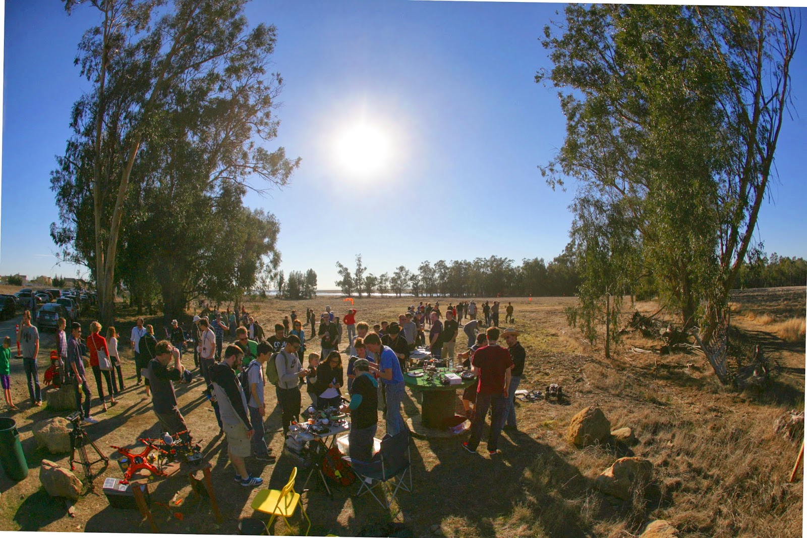
Drone fly-in


drones06.jpg


drones01.jpg

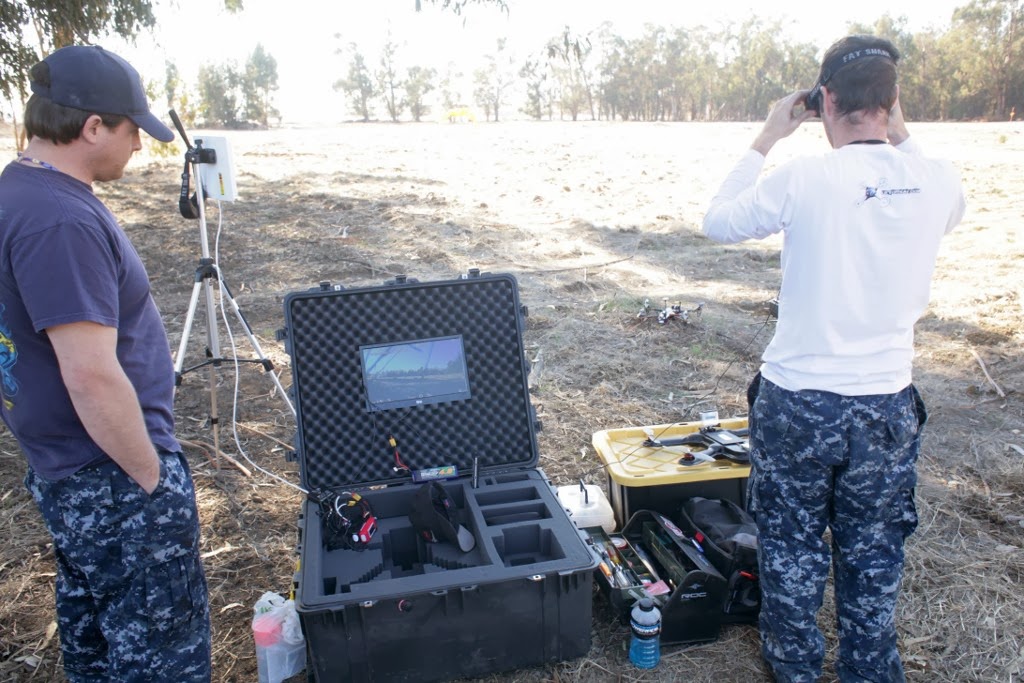
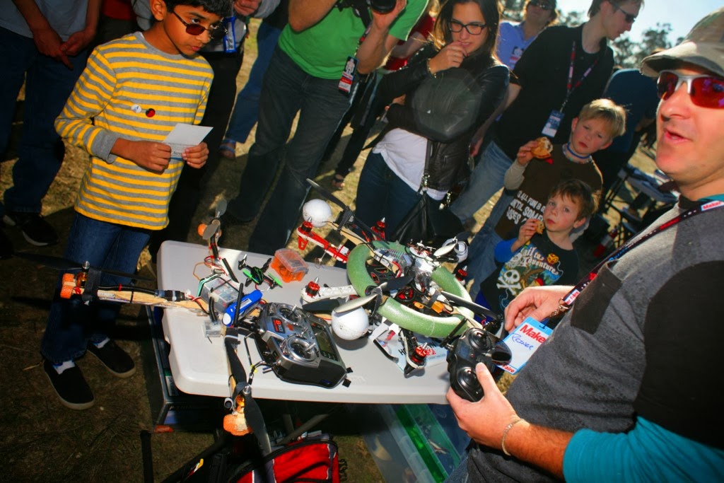
A complete home entertainment system for FPV, but with the same old analog NTSC video.

drones02.jpg

For someone who reads rcgroups.com & diydrones.com, there was very little new to see, besides the real life equivalent of the photos.

drones03.jpg

 Thought that was very Silicon Valley: a stock reference board for a standard set-top box with the standard server room BNC, RCA, RJ-45, connectors untouched, all to send very delayed video over LTE.


drones13.jpg


The most hated vehicle there.  It was really wobbly.


drones04.jpg

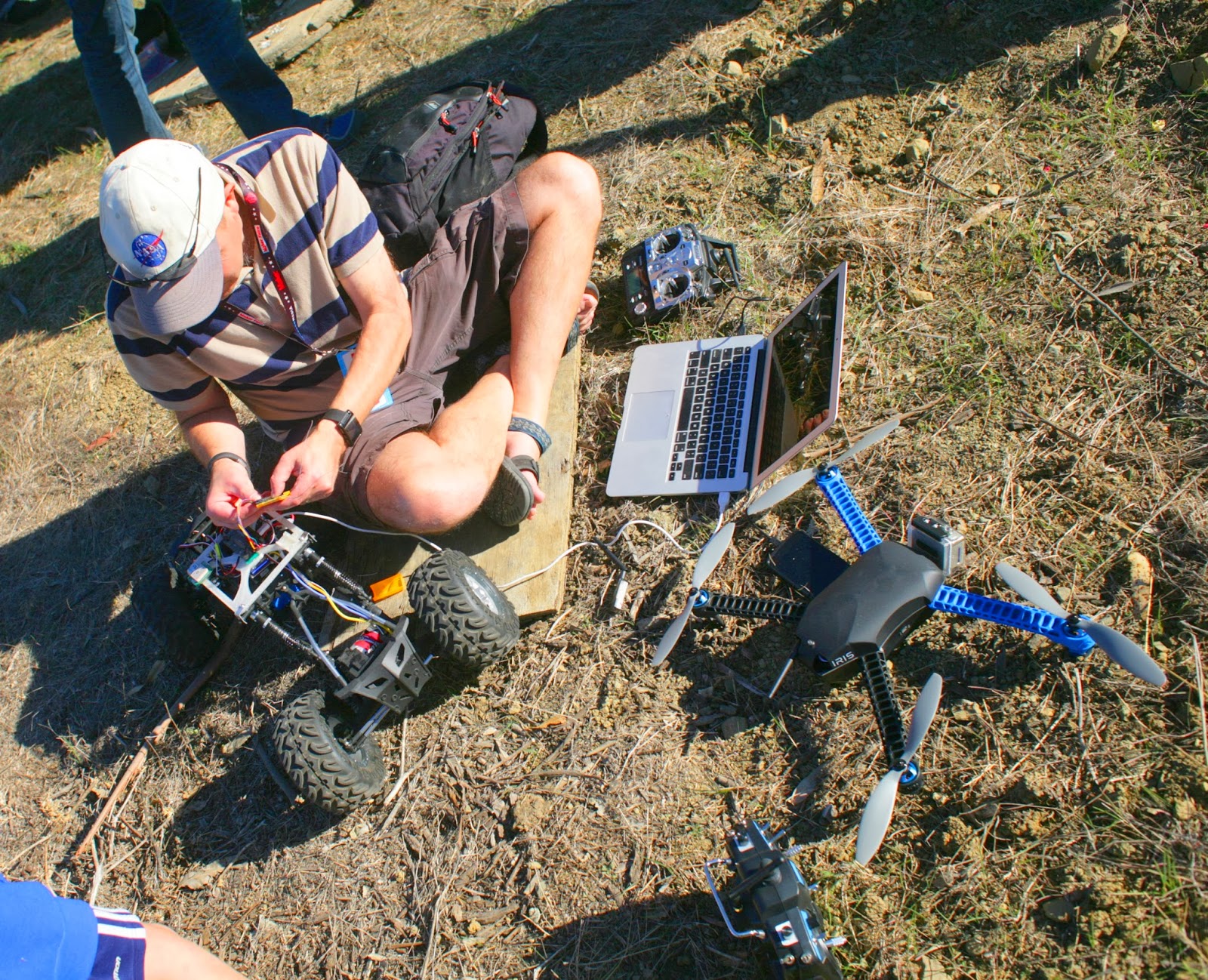
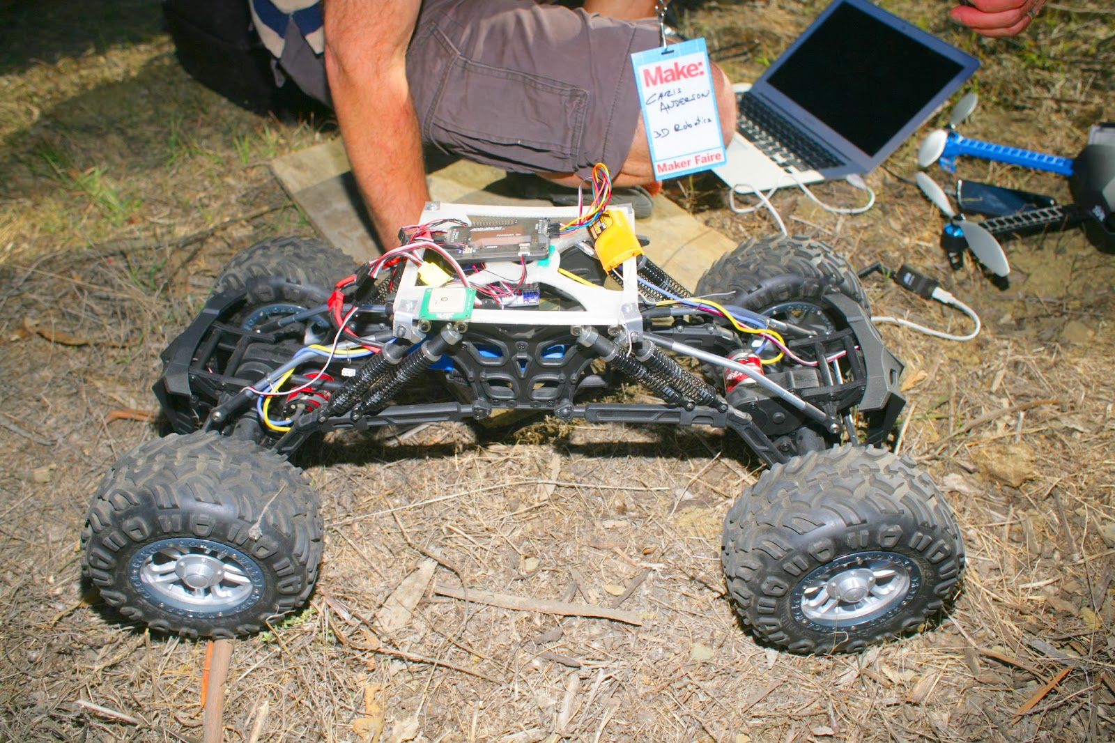
 Some guy trying to get a rover to work.  Unfortunately, it only rolled a few feet, very slowly.

drones05.jpg

A chassis that would normally cost $200 on hobbyking was $20 at a garage sale.  Could desperately use something like that.

drones07.jpg

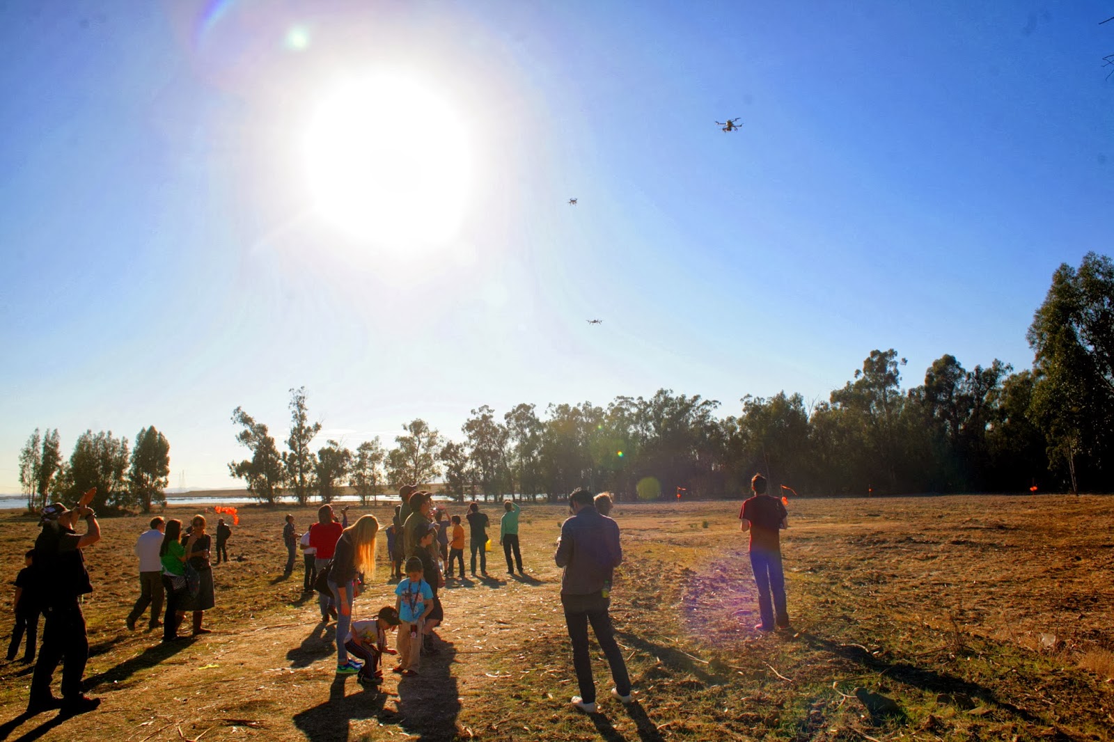
 Everyone congregated on a south field, while a north field shown in previous videos was empty.

drones08.jpg

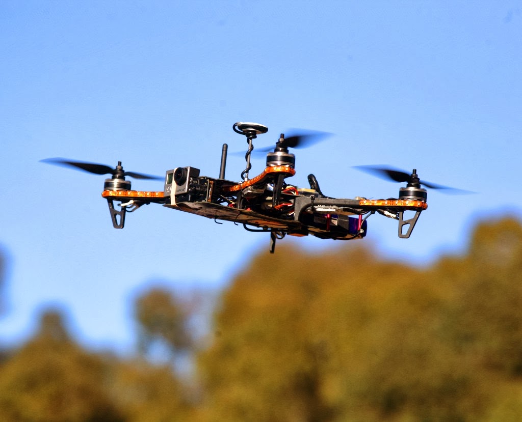
Standard quad copters.

drones09.jpg

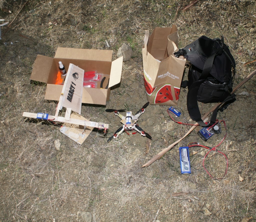
 Some ghetto indoor vehicles.  Marcy 2 was a complete disaster, as a vibration problem, wind, & uneven ground screwed up her indoor navigation sensors.

drones10.jpg

drones11.jpg

 3D Robotics dominated the attendance.

drones12.jpg

There was very little autonomous flying, only a few times someone would go into loiter mode or a lost radio link would send a DJI Phantom into the trees because some arcane loss of signal setting wasn't set right.  No-one replicated any Marco Robustini demos. 


The stock 3D Robotics Iris hovering far from the trees looked like it wasn't going anywhere, but it did look twitchy.  1 DJI guided black sheep was hovering motionless near the trees.  It drifted a long way, as it tightly tracked the drift of GPS near the trees.  Still looks like perfect calibration, perfect prop balancing, perfect vibration damping, & satellite visibility is a big part of the results.


Despite the improvements in sensors & software making autonomous flying much more accessible than years ago, there was little interest in it.  After all the expense & calibration, people would rather fly manually than program a route & watch it play back.  There was certainly no interest in making a timelapse movie from 1 place in the sky.
Read more…
3D Robotics

Major new update for APM:Plane code

3689569417?profile=original

Good news from Andrew Tridgell and the rest of the APM:Plane (ArduPlane) dev team: they've pushed out a major new release (2.77). Major changes include: lots of updates for PX4 and Pixhawk, dual sensor support on Pixhawk and new throttle arming code.

The following is from Tridge's release announcement. Please post any questions or comments there. 

Pixhawk updates

The biggest set of changes are for the PX4 and Pixhawk boards. The Pixhawk production boards started shipping a few weeks ago and include some nice hardware features that didn't make it into the 2.76 release. The most important of these is dual sensor support. The Pixhawk has two gyros and two accelerometers, and (if you have an external GPS/compass combo) dual compass as well. In the 2.76 release only one of each of these sensors could be used. With the 2.77 release the health of each sensor is monitored and if one sensor fails the second sensor can take over. In addition to failover support the code logs both sets of sensor values both to MAVLink and to the logs on the microSD card, which is very useful for diagnostics. We are also working on dual GPS support which we hope to get into the next release. I have test flown the dual-GPS code a few times, but I didn't consider it complete enough for the 2.77 release, so I have left it out for now.


Arming support
The most user visible change in this release is a great contribution by Michael Day adding new arming code. For those of you who have flown APM:Copter you will know that you need to arm the copter before you can fly using the rudder stick on your transmitter. That can be a great safety feature for electric aircraft, and now APM:Plane has the option of the same type of arming code.

For the plane arming code we decided to make arming optional so as not to surprise existing users too much. Have a look at the documentation for the arming parameters for how to setup arming in APM:Plane 2.77.

Parameter storage
Another major change for this release is the way parameters are stored on PX4 and Pixhawk. In previous releases we stored parameters on a file on the microSD card. That usually worked fine, but recently there have been a few too many issues with FAT filesystem corruption of microSD cards, especially when powering off while writing to the SD card. For this release we have moved all parameters to the EEPROM on the PX4 and the FRAM chip on the Pixhawk. This makes parameter storage independent of the microSD card, avoiding parameters becoming corrupt due to microSD card problems. Parameters from a microSD card will be automatically copied to EEPROM/FRAM when you upgrade to APM:Plane 2.77.

Improved relay code
The relay and servo set code has had a major overhaul, with up to 4 relays now supported for MAVLink control and much better support for the DO_SET_SERVO, DO_SET_RELAY, DO_REPEAT_SERVO and DO_REPEAT_RELAY MAVLink commands. Along with these changes is a new parameter BRD_PWM_COUNT which allows you to specify how many auxillary PWM outputs to enable, with the remaining outputs being available as digital relays. This allows you to re-assign some of the aux servo outputs on Pixhawk for use as relays, by setting the RELAY_PIN, RELAY_PIN2, RELAY_PIN3 and RELAY_PIN4 parameters. The pin numbers for these pins start at 50 for the first aux servo pin, and go to 55 on Pixhawk.

Improved logging
There have been logs of logging improvements in this release. Apart from the dual sensor logging, we can now transfer on-board log files to the ground station over MAVLink, which makes it much easier to get detailed logs without having to pull a microSD card out, or boot to the CLI. We're hoping to remove the need for the CLI completely in a future release, doing everything over MAVLink.
The new logging code also includes the git version number of APM and (if needed) the PX4Firmware and PX4NuttX repositories used to build the firmware in the logs. This makes it easier to track down any issues to the exact code used.
Another important logging change when used with the new ARMING_REQUIRE option is that logging won't start until you arm. This prevents lots of small log files from accumulating, wasting space on the APM2 and cluttering up your microSD card on PX4 and Pixhawk. 

Loiter change
A small change in the loiter code now makes it possible to change the direction of loiter while loitering, by setting the loiter radius to a negative number. This is mostly useful for testing, but it was also requested by one user.
Health reporting
The reporting of sensor health to the ground station is much improved, allowing the operator to know more quickly when a sensor has failed. This includes the health of a digitial airspeed sensor, as well as inertial sensors and the compass.

Initial Sonar Support
This release includes the beginning of sonar support for landing. This is still experimental, and thus far it can't actually be used to control landing, but you can configure a sonar and log the recorded sonar distance and voltages for analysis.

Reverse throttle fix
A bug was fixed in the handling of throttle failsafe for internal combustion aircraft with reversed throttles. If you fly IC and have throttle reveral then you need this fix!

HIL improvements
Lots of improvements were made to HIL support, including better handling of slow HIL connections, plus much faster HIL servo updates. It now flies a lot better in HIL. Another useful feature is that the SIMSTATE MAVLink message is now included in HIL MAVLink messages, which makes it possible to compare the true attitude with the attitude that APM has calculated from the sensor input. This is very useful when diagnosing HIL issues.

More telemetry ports
On Pixhawk and PX4 you can now have a 3rd telemetry port, allowing USB and two serial telemetry ports to be active at the same time, which is very useful when you have an onboard computer.

Geo-fence return altitude
Another improvement from Michael Day is the inclusion of the FENCE_RETALT parameter which allows better control over the return altitude on fence breach.

Airspeed fixes
There have been a few fixes related to airspeed handling. One is to handle the case where airspeed reading too low due to the ARSPD_RATIO being too low. The airspeed autocal code didn't fix this as it only ran when airspeed was above the minimum airspeed. We now run the airspeed autocal code if either GPS groundspeed or airspeed is above the minimum airspeed.
A second airspeed related but was to fix a scaling factor for true airspeed in the pitch controller (thanks to Paul Riseborough for the fix!).

Upcoming Changes
There are a lot more changes in the pipeline for APM:Plane! The biggest thing being worked on right now is the new Extended Kalman Filter (EKF) code from Paul Riseborough for attitude estimation and inertial navigation. It is producing great results, but we decided to hold off on releasing it as we want a bit more testing first. 

Read more…
300km

Whale Rescue

On the weekend I flew in support of a whale rescue at Farewell Spit in Golden Bay, New Zealand at the invitation of Project Jonah, a whale rescue NGO

https://www.facebook.com/projectjonah

1518832_10152142166457439_1838562014_o.jpg?width=750

About 60 pilot whales had stranded over night high up the beach. About 10 died or were euthanized and the surviving 50 were successfully re-floated at high tide around midday. The plan was for me to fly overhead and monitor their progress via FPV. If they headed out to sea then everybody could relax. If they headed back to the beach then we would have advance warning of where they were going and the rescuers could create a human chain to prevent them beaching again. 

As it turns out I wasn't much use, the whales beached again about 10 minutes before I got airborne. If I was half an hour earlier my UAV could have provided real time situational awareness that would have enabled the rescuers to swing into action.

Farewell Spit is a common site for whale strandings. The beach has a very gentle gradient, the distance between high tide and low tide is up to 2 km in places. The photo above was taken at low tide, a little over 1km away from the high tide mark. It's not apparent from the photo, but the whales were grounded just 100m from deep water. My contact person was the Project Jonah general manager, he told me that the proximity to the deep water would have meant a human chain could have been particularly effective at preventing them from stranding.

The wind was strong the whole time I was on site with gusts to up to 50km/hr. I flew one mission and it was the bumpiest flight I've ever done. The flight log shows it got buffeted to 60 degrees of roll (it felt like 90) as I was taking off in stabilize mode. It got buffeted to 80 degrees later in loiter mode. The plane has a normal cruise speed of 40km hr so I struggled to make headway upwind and I hit 100km/hr at one point downwind. My gimbal could tilt but not roll so the wild movement made the picture pretty unstable but the whales and rescuers were clearly visible from the air. It was live FPV only, no recording to share here unfortunately. I flew in auto mode initially and used guided mode and loiter to remain above the area the whales were. My airframe (Bormatec Maja, 2.2m wingspan) wasn't really the best airframe for the conditions. It was too slow in flight speed and too docile in maneuverability. I would say a small flying wing might be best.

I packed up my gear after my flight, then put on my wetsuit and rushed down the beach to help with the rescue effort.

The situation when I arrived was much as is shown in the photo above which shows about a quarter or third of all the whales affected. I was directed to help a group of 5 whales and I worked with three others for an hour or so keeping them covered (the sheets blew off in the wind), keeping them wet and cool, and digging trenches by hand under to allow their pectoral fins to rest in a more natural position. The whole point was to keep them alive and in good condition until they could be re-floated when the tide came in. I wish I could have stayed longer, many people had been there all day, and would be until dark.

It was an experience that I'll remember my whole life. There were so many feelings that changed from moment to moment as I worked and took in the situation. Mostly I felt pride or a sense of service from being there with my sleeves rolled up, but that alternated with frustration, why had the whales beached themselves? What's the point of all that effort if they're just going to do it again once they're re-floated (this was already the third time in two days)?

But the thing that struck me the most was a discussion I had with one of the Project Jonah co-coordinators. I told him they could buy a reasonable FPV setup for under $1000. He said that sounded really nice but as a volunteer organisation they couldn't afford it. He said that he paid for his own flights down from Auckland (about 1000km away) and when they need to hire a spotter plane to track the whales they paid for that from their own pockets. It's incredible to meet people that have such passion. I'd driven 200km to be there and spent most of a day, but I suddenly felt dwarfed standing beside him.

My point in writing this blog was to tell about the potential uses for a UAV and relate my day saving the whales. But I can't help myself inviting donations for Project Jonah. If any manufacturer(s), or individual(s) were prepared to donate a suitable airframe, and components then I'd donate my time to set it up and train them in its use. (I can't drop everything to attend a stranding so if it's going to work it will have to be Project Jonah owning and operating it). 

By way of a progress update it's a little over 24 hours since I was there. The whales have been floated, and are swimming in deep water but are still milling about not far from the danger zone. Only time will tell if they strand again or head out to sea. See the Project Jonah Facebook for progress updates and more info. https://www.facebook.com/projectjonah

Read more…
Moderator

T3 Season 2, The Model: heading to the finish.

3689569357?profile=original

Just a gentle reminder that the current T3 round closes on the 1st of Feb. If you have entered before then you know I am fairly flexible with my calendar and observance of it. 

What can I say about the entries so far other than quite amazing! The flight planning and post production involved will have taken perhaps hundreds of hours and all the contestants can be very proud of what they have achieved.

The thread is here, http://www.diydrones.com/profiles/blogs/t3-season-2-the-model It contains a great deal of knowledge!

The T3 started back in 2009 the complete list of contests to date is here http://diydrones.com/notes/Contests

A couple more images from it. None of these images point to the results in any way!

3689569310?profile=original

3689569245?profile=original

3689569379?profile=original

Read more…
MR60

Suspended quadcopter design / build log

3689569063?profile=originalHi,

Here is a short build log of a new quad frame design. I had three objectives:

1-Reduce vibrations. We are all striving to reduce vibrations in our multicopters especially if we want to use ardupilot and make nice stable FPV, pictures or movies.

2-Make it light, but strong enough to embark fpv and small AP cameras,

3-I am tired of the classic sandwich center plates design we find in all multicopters, consisting of two center plates holding the arms by compression. Not only this compression design is heavy but it also transmits vibrations by design to the plates carrying electronics and cameras/gimbals.

I also liked the idea Forrest Frantz used in his light tube construction, where there are no center plates, just two carbon booms crossing.

I did not have any carbon tubes in my basement but I had U shaped aluminium booms. Then came this design idea : let's avoid the center plates by crossing the two U shapes booms. This is done simply by sawing four slots that are as wide as the U side's thickness and half the U side's height in length.3689569226?profile=originalIn such a way the two booms "merge together" as shown in the picture, as if I had an aluminium cross in one single piece.

To reinforce the cross I added a screw and bolt at the center.

3689569262?profile=original

The result is a perfectly rectanguler cross, very rigid and light.

Next : to prepare where the motors will be placed. The objective is to make a platform up to 10 inch propellers that will not blow on the suspended electronics platform. Therefore I hired my son to cut 10 inches disks:

3689569181?profile=original

I did not have a carbon fiber plate so I reused what I had, a piece of birch wood, 5 mm thick. This is light enough and rigid enough for my need. I will later replace this birch wood plate by either a carbon fiber plate or a laminated balsa plate.

The paper cut disks allowed me to match the propeller space with the suspended plate to be cut in the birch wood piece:

3689569045?profile=original3689569080?profile=originalAfter positionning the paper disks, I drew the shape of the center plate carefully, checking everything is squared. An X quadcopter is assumed here.

Afterwards, the center shape was cut and put aside. No holes were yet drilled as first the suspension system had to be designed and placed on the aluminium booms.

I used anti-vibration dampers from Secraft. They are very nicely designed as have silicon rings in two perpendicular directions (unlike the expensive cinestar similar system).

 3689569157?profile=originalThe challenge here is to hang these Secraft dampers so that the plate will be leveled. However with the way I mounted the two booms, I had the issue of having two flat arm sides facing down and two arms with the U opening facing down. To solve this I cut a piece of boom (at least the length of the Secraft damper, about 7 cm) and screw it upside down as shown in picture below:

3689569123?profile=originalAnd it looks like this once everything is screwed on:

3689569091?profile=originalAt this stage the birch plate, as seen on picture, is cut.

3689569170?profile=originalWe place the plate beneath the cross to mark the holes that need to be drilled. This way we are sure to get it right (by measurement you are always off due to errors and/or imprecisions during the build)

3689569140?profile=originalHere is the final result:

3689569209?profile=originalThis system provides an isolated mount plate to carry everything :  APM, cameras and all of the electronics in total isolation from the vibrations sources (motors/arms).

It gives enough rigidity not to confuse APM's sensors but provides still enough dampening. I was surprised how the dampening is not too soft. If needed there is even the possibility to replace the red soft silicon rings by the harder black ones from Secraft.

Thus far the total weight is:

3689569151?profile=original=537grams. So adding 150g of APM+electronics, 80 grams of ESCs, 400 grams of motors and props, I should be around 1kg without battery,  for a 40 cm motor-to-motor quadcopter, with I expect excellent vibrations dampening results.

I must now order some motors and ESCs after a few simulations on eCalc.

Any suggestions for a 40 cm quadcopter motor/props combination ? (max prop 10/11 inch). I could use the classic 3DRobotics 800KV/10 inch APC. But It would be nice to use maybe lower RPM if the weight is low enough.

Read more…

Working on endurance options

3689568885?profile=original

I've been working on getting a better range and endurance. This QAV-540 weighs 5.5 lb's and I just flew it for 18 minutes today. Previously 16 minutes was my record, the change is that I went up one inch in prop size. This is not stripped down for endurance, I want something that will fly a long time and do some work, like carrying a Gopro. This one was carrying a Gopro and a gimble.

Trying different battery types will probably be next as well as even larger props. I am using a FRsky Taranis and am using the X9R receiver, but will be changing over the the Rmilac LRS system. I have been using Open Pilot so far but will probably switch to the Pixhawk. I haven't set up the FPV yet, but will be going to a 1.3GHZ very soon.
Anyway, I'm pretty stoked about the 18 minute flight, but looking for better!

3689568799?profile=original

Read more…
3D Robotics

3689568707?profile=original

From The Wire:

To reinforce her concerns about the use of commercial drones, California Senator Dianne Feinstein told her peers on Wednesday about an encounter she had with a drone at her house. 

...

Feinstein said she encountered the flying robot while a demonstration was taking place outside her house. She said she went to the window to peek out — and “there was a drone right there at the window looking out at me.”

...

The Wire spoke by phone with Feinstein's spokesman Brian Weiss, who confirmed that the incident happened at the senator's house in San Francisco several months ago. At about the time, it seems, that Code Pink showed up to protest Feinstein's support for the NSA.

On June 15, the anti-war group held a protest focused on Feinstein, which included activists in disguises and, yes, two remote-controlled helicopters, which might creatively be described as drones. Here's video of the event.

If you skip ahead to the one-minute mark you can see the two helicopters that were at the scene, including one very similar to the small pink helicopter at right. Photos taken that day show the helicopter more clearly. Steve Rhodes, who took the photos, confirmed to The Wire that the helicopters flying around outside Feinstein's home didn't have any cameras, so they weren't "looking in" anywhere.

Code Pink's Tighe Barry, coordinator for the group in D.C., told The Wire that flying these toy helicopters is common at their protests. He participated in one such protest in San Diego at the home of the president of General Atomics, makers of the much-more-scary Predator and Reaper drones. The toy helicopter, Barry said, was purchased on Amazon, as this one might be. And Feinstein is a regular target for the group. "We've held many, many, many vigils there over the years," he said.

So was this the drone that frightened Feinstein so much? Weiss, the senator's spokesman, didn't know what kind of drone the senator was describing. But if it was a blind one the size of a crow, the Senate Commerce Committee can sleep a bit easier tonight.

Read more…

3689568730?profile=original

We have developed a version of the SurVoyeur mk-II, the 'c' version, which has a new nose housing a gimballed, stablized EO and IR camera combination.

This gimbal houses the FLIR QUARK 640 X 512 pixel Thermal camera, fitted with a shutter to enable flat field correction,  and also houses the Sony EX11 Colour Block Camera.

Both camera are fully controllable from the ground station, colour modes, zoom where applicable, AGC, etc.

The gimbal is stabilized and fully steerable from the ground station. We are currently working on making accurate fitment jigs to bore-sight the cameras to the IMU, to enable accurate line of sight determination to allow automatic tracking of designated 'targets'.

Here are some photos of the various parts of the Gimbal, and the Gimbal fitted to the aircraft.

The two cameras with the QUARK shutter mechanism:                                   The assembled Gimbal:

3689568679?profile=original

3689568343?profile=original

Pre-assembly:

3689568758?profile=original

3689568751?profile=original

3689568775?profile=original

3689568864?profile=original

A short video of the gimbal in motion:

https://www.youtube.com/watch?v=0xlB0HXT520&feature=youtu.be

Flight times are 70minutes at sea level 25deg C, 55 minutes at 1600m ASL, 40deg C.

Additionaly an 18mpixel Canon stills camera, stablised in roll, is fitted in the belly bay , under the wing, as was in the original mk-II aircraft.

search for SurVoyeur on DiyD for other blogs on mk-I and mk-II if interested...

The Nampilot.

Read more…
3D Robotics

Bay Area drone fly-in on Monday

3689568788?profile=original

If you're in the Bay Area, this is just a reminder that MAKE is hosting a drone fly-in at the Paintball Jungle in Vallejo on Monday, 1-4pm. I'm planning to be there with some kids, who have been wanting to try their hand at paintball. Presumably the drones and paintball fighting will be separated, but who knows?.  [UPDATE: Turns out that the paintball field will be closed for this event, so it's drones-only. If it's paintball you want, you'll need to go there on a Sat or Sun]

RSVP here. 

Read more…
3D Robotics

Redesigning a quadcopter leg for 3D printing

3689568664?profile=originalA great exercise in using CAD and 3D printing to improve drone design from MAKE and 3D Systems:

My job at 3D Systems gives me the 3D tools to tinker at a high level. The highest level, really, considering we’ve got scanning, design, and 3D printing right here. I’m a lucky guy. So when my quadcopter started to show some of its design flaws, I took to a Batcave’s worth of equipment around here that’s just waiting to be used.

3689568643?profile=original

Comparison: Redesigned boom in green, original boom in purple. Notice the huge difference in leg length.

There were a couple of issues with quadcopter design that kept me up at night:

  1. At the end of each boom, where the motor mounts, there is a thin section. The motor mount section is actually thinner than the rest of the boom and has no support. As a result, during a hard landing (I never claimed to be a particularly good pilot), the leg would snap right off.
  2. Those perpendicular legs that stick out at the end of each boom support the quadcopter during landing. But the original legs were only about an inch and a half long, plenty long to land the quadcopter normally. But I’m also a sucker for aerial photographs, and if I wanted to mount a camera under the quadcopter, these short legs didn’t give me enough clearance to land, unless I wanted to land on the camera.

The Fix

Now, I know what you’re thinking, and, yes, I did consider a whole load of duct tape. But that wouldn’t give me the warm fuzzies like a redesign with pretty 3D printed components. Besides, a redesign would be a good learning experience with the software that I sell.

I started by scanning the original boom, which I had no problem with otherwise, and working from a model based on that scan data. The original sidewall of the boom was about .375 in. tall all the way across (with a rounded edge at the bottom) until you reached the motor mount, where it suddenly dipped to about .1875 in.

Comparison: Redesigned boom in green, original boom in purple.

Comparison: Redesigned boom in green, original boom in purple. Notice the huge difference in leg length.

Comparison from the other side. Notice the huge difference in leg length.

Comparison with original boom in the foreground. From this side you can see how the boom thins out at the motor mount above the leg.

My redesign added thickness to the boom overall. I also squared off the edges and tapered the sidewall length from the body side of the boom down to the leg. The redesigned boom starts at about .5625 in. thick by the body and slowly tapers down to about .375 in. thick by the leg. The leg side is much stronger than it was at only .1875 in. No more snapped legs. Smiles. Kittens rejoice. Cured meat for everyone.

Now on to the leg length issue. I did a couple of things here. First, I made the leg longer, almost doubling the overall length from 1.875 in. to 3.5625 in. But I also added some extra strength by thickening the legs pieces and crossbar by .125 in. each, and I moved the crossbar so it’s parallel to the ground. I wanted to make everything thick and burly, as you can see. That way the risers would be able to withstand the stress upon impact with the ground.

The redesigned boom was printed on a ProJet 6000 SLA 3D printer.

The redesigned boom was printed on a ProJet 6000 SLA 3D printer.

3D Printing and Fitting

To manufacture the piece, I went with the 3D Systems ProJet® 6000, which is a high-definition crossover SLA (Stereolithography) 3D printer that’s easy to use in an office environment. It took around 15 hours to complete the print, and it looks amazing. Perfect detail and a nice smooth surface finish. Now if I could just get one of those bad boys for my home, I could start my own RC vehicle company.

Bolting the boom onto the chassis was essentially uneventful. It fit perfectly the first time without any modification, hammering, tooth grinding, cursing or anything of the like. So I’ve got the first of four stronger quadcopter booms, which will provide plenty of clearance for a gimbal or rigid-mounted camera on the bottom.

Read more…

I had the Oculus Rift lying around and decided to do a little project today to integrate FPV video into a 3D environment. It's tempting to just make a surface and project the video on that, but I thought that it would be more useful to use head movements to switch between informative displays instead of buttons and see where things go from there. Since the computer will be in the field anyway, you might as well use 3G to download maps or use databases to enrich the FPV experience. Because the Rift is so immersive and the video is pretty much static, I didn't try to create any illusion (that'd lead to motion sickness), so just made it explicit that it's a projection of some sort on a surface.

This virtual ground station has prerecorded video projected on a screen with a supporting display on either side. One side shows some diagnostic information from the plane, the other shows the map and thus the location of the craft in the actual world, along with some navigational information. In theory, you can have any support information screen you want, it depends on the task.

I ended up using the UDK, because Unity requires Pro due to shader features on the Rift and this requires a $1500 investment (you get 4 months free for the Rift with Unity).  For non-commercial use, the UDK is free.

A remaining challenge is to how to get telemetry and the video into the 3D environment with the scripts at low latency.

There's another opportunity to make this more virtual and engaging by utilizing a 3D plane flying over a holographic projection table, showing the location of your plane in 3D above the map with a line demonstrating its intended route. You could even make that map 3D utilizing DTM's.

The challenge for VR is that interaction by the pilot with any application is limited and you can't hold on to three controllers at the same time. Rich interactions like many keystrokes on a keyboard are impossible. Nevertheless, it'd be interesting to see what can be done by game elements like room triggers and other interaction methods to basically add some more functionality to this environment.

Another limitation will be that tasks requiring precision (for example placing a waypoint) are rather difficult to do or take too much time. That'll take some time figuring out a useful interface for that objective.

The things I learned were:

  1. The Rift can be useful to construct a relatively large space full of information. In the end it's like having three monitors on a desk with poor resolution (like 320x200). The Rift does not have appropriate resolution for reading small text, so things have to be graphic, iconic and relatively large.
  2. You can move about in 3D space to essentially zoom in or out. A complication here is if you fly manually, you don't have hands left to control your position in the virtual station. For autopilots that's less of a problem.\
  3. Content which is now 2D on a desktop screen can be turned into iconic 3D representations. Like the plane example above, where you have a large "table" with a map from google earth on it. Other 3D iconic representations can be used to represent other events or actors, etc.
  4. Video perception is reasonable, but the screen itself (the object) can be made much larger to achieve better visibility. It would require moving your head about, but fatshark glasses for example require you to move your eyes around to see all the corners of the screen.
  5. This is an opportunity to get rid of OSD information obscuring the 2D display.
  6. There's no way you can use this technology on moving vehicles (motion sickness and disorientation)
  7. I expect that using the Rift to control the camera pan/tilt gives you motion sickness, because the latency is too high.
  8. (theoretically and philosophically): If you enlarge the space and attach elevators and other interfaces with databases, you can create a planning room in the back and make the tasks that a person is responsible for location dependent. So, depending where a person stands in the VR environment, they become responsible for particular tasks. That means you could in theory move about in this 3D space and take over from the pilot, or walk into the back, do some map planning and get back to the original task.
  9. There are other opportunities where you can take advantage of their location in VR space; for example establishing communication groups. As soon as you walk into this virtual circle, you get added to their radio channel.
  10. The ground station here is clearly a ground base somewhere. The coolest Virtual Ground Station (let's coin the term VGS) would be a model of a vehicle (star trek enterprise) with a projection of the video on the forward bridge window and supporting consoles/displays around the bridge that are monitored/controlled by your operators. The idea for the pilot to be actually onboard in a "virtual bridge" is a pretty cool concept. It then becomes more natural to think about other virtual elements, for example the planned vehicle route from APM and project that around the vehicle. That would allow you to look around and see intentions and all virtual artefacts (virtual representations of data in a 3D space, essentially).
  11. I reckon that the maximum time one can spend in the Rift is around 30 minutes, before you get too tired or slightly motion sick.
  12. And then your phone rings.....

Because the Rift is so incredible immersive, this environment really gives you the feeling of being there. in this application, the line between reality and virtuality is really blurring, because your interactions with this environment (or from outside of it) really has an impact in the actual world. That's not a statement that's pro or contra, but an observation that it's not yet 100% known how people should take care after having used the Rift. Should they take specifically designed breaks after 30 mins of use to "get back to the real world"? 


Read more…

A World Breakthrough in UAV Propulsion

3689568566?profile=original

Energy Density of up to 0.65-0.8Wh per gram.  Very Exciting!

Excerpt from Manufacturer's Website

AEROPAK is an ultra-light power supply enabled by fuel cells, designed to increase flight endurance for small electric Unmanned Aerial Systems (UAS). It uses an on-demand hydrogen supply system from a chemical stored in a swappable cartridge.

The special characteristics of AEROPAK-1 allows to reduce weight progressively over the course of a flight, by purging spent fuel during flight. This means the average energy density of the system can increase up to 675Wh/kg for a 2 kg system, weighing 1kg after consuming all of its fuel.

3689568541?profile=original

Excerpt from Isreal's Homeland Securty Home

A cooperation between Israel and Singapore has resulted in a breakthrough in powering unmanned air systems. “This will change the world of UAVs and opens many new paths for using them in many applications” an Israeli source said.

3689568587?profile=originalInformation Document

3689568604?profile=original

Read more…

Building an ardu-rat-quad. :-)

3689568459?profile=original

Basically, I thought I'd blog my latest build, to see if it offers the community any helpful ideas.

I approached this build with a couple of objectives - to build a test bed for arducopter features and new releases, to clear down some of the parts bin and older parts.

Now a parts bin special is nothing fancy, but there are a few important considerations:

- vibrations. It's very likely your will build it using old props, old motors, and an old frame. Likely these have all been crashed at some point. That's why they were in the parts bin, admit it...;-) All of these will vibrate. So it's important you pay more attention to vibrations than normal. Your design should emphasise this

- design. Just because you have 4 motors, four props and 4 ESC's does not mean it will fly. ecalc.ch is your friend, as always. Don't spent nights building it, and finding out won't fly

- compatibility. Last time this airframe was probably in the air, arducopter ran on a single 1280. Well, it doesn't anymore.

So what did I do?

1. Airframe

- Measured all the M2.5 bolts and nuts. I chucked any that were bent or rounded. If this frame has been apart in the past, some of the holes will be slack. All frame bolts now use loctite to compensate for their age and the likely higher vibe levels.

- Double checked alignment. As it was, I needed to bend Motor 4 slightly.

- As always I labelled everything...motor number, rotation, arm number, servo leads all numbered. Frame is also marked with my contact details.

3689568308?profile=original

- I added some jdrones anti-vibration mounts. My 2216-11's aren't the smoothest anymore, so I start vibration mitigation here.

- I like to cable tie behind both joins of the motor bullets, and keep the bullets visible for preflight checks. These are more important now, because the increased vibes will shake stuff loose.

- I re-balanced the props. Just in case.

- I used 4 very strong rubber risers to insulate the landing legs from the frame. This is a slight modifier on the "Clean / Dirty frame" design used by others. I also used the anti-slip rubber matt from the car (used to stop your phone slipping around) to stop the battery moving around, and to providing yet more damping. That's an 11,000 3S maxamps.

3689568379?profile=original

- The legs needed to have washers added on the inside of the cross members to stop them wobbling. This is important, because movement of the compass during compassmot could be misinterpreted.

2. Electronics - All normal good designs apply here, starting with vibes. 

- I started with the APM case; the APM board now sits on top of the rubber washers. I have no idea if this will have any effect, but it should all add up

3689568484?profile=original

- The whole electronics stack is mounted on 4 rubber risers, and the APM will get a 3D printed vibration plate from shapeways soon (currently sitting on moongel). I have this mount on my workhorse, and it's a good un'. 3DR APM is original but compass trace now cut, the telem is a chinese knock off, and the Orangerx is junk, but maybe the 2 sats that are coming from HK will improve matters.. Not in shot - strong black tape not on all my rx sat connectors, following Saturday crash (which was partly caused by sat connectors coming loose). Rx and Telem boards mounted on 3M anti-vibe double-sided blocks.

3689568324?profile=original

- GPS is a 2.5 unit, and the compass is from china. Both are mounted on a DJI style post, drilled and bolted into the top plate of the frame. I have extended the cables using aftermarket ones, to keep the routing tidy. Can't quite see it, but there's a tiny rubber square between the GPS and the compass. Again, vibes...Post definitely works. This is the compassmot score ;-)

3689568394?profile=original

Note 3DR....PLEASE PLEASE PLEASE make 30-45cm version of the ridiculous 5/6 cable please, so I can route it all neatly!!!!

3689568512?profile=original

And lastly, I pulled together an old gimbal, just for the sake of it, on a "old" martinez. :-)

Any question on how to revive an old airframe for modern use, let me know.

And to sign off, how is it? Well, I'm going to run autotune on Saturday and find out!

Read more…

Hydrogen Fuel Cell Polarisation Curve

Hi all,


The latest update on my project for the chemical engineering nerds out there, how to get a polarisation curve from my fuel cell using a raspberryPi controller.


Why a fuel cell; if you haven't followed my other posts, they can provide cruise power for hours, greatly increasing the endurance of a RC plane or UAV.


Unlike batteries, fuel cells do not lose voltage with time because you can keep feeding it fuel. Much like a car engine keeps working until the fuel is completely gone, whereas a battery has a gradual reduction in it's output with respect to it's state of charge (SOC). However, the voltage does vary with load, and this relationship is captured in a polarisation curve.


Hope you find the video interesting and inspiring, if so please click LIKE!


Regards,


Simon

Read more…