A buddy of mine was walking around in San Mateo, CA (a city just south of San Francisco) and found this great sign... I only wish it said "Lost Drone" but this is still pretty good. May you never need to post one of these. If you want to see his instagram post http://instagram.com/p/j7itSURpIT/
All Posts (11086)
Sort by
The first flight of my Super Sky Surfer 2400 equipped with an APM 2.5 went well. Went through Stabilize and Loiter modes just fine. I didn't prefetch maps on mission planner so I didn't try out any waypoints. That's next time!
Open Source Laser Range Sensor Converts the Speed of Light into the Speed of Sound
Press Release, February 2014:
In a direct attack on both the laser rangefinder market and the ultrasonic rangefinder market, LightWare Optoelectronics (Pty) Ltd, a South African based manufacturer of laser rangefinders, has begun production of an open source laser sensor (OSLRF-01) that can convert signals traveling at the speed of light into signals traveling at the speed of sound. This sensor has all the benefits of a laser rangefinder, like direct aiming, long range, immunity to noise and wind and high accuracy but non of the headaches associated with the super high speed circuitry normally found inside laser products. Instead, the OSLRF-01 outputs analog signals that look just like those found on an ultrasonic sensor. These speed-of-sound signals can easily interface directly with the ADCs of a microcontroller where conventional ultrasonic signal processing and timing algorithms can be applied to the data.
If the speed of sound is too slow for you, there is a control input on the OSLRF-01 that lets you select what Mach number you want to work with, anywhere from Mach 0.1 up to Mach 5. Running at higher Mach numbers means that the analog signals get faster and the time it takes for the laser/ultrasonic pulse to make a round trip gets shorter. So if your processor can handle the additional speed, you can have a quicker response time.
The OSLRF-01 can be used as the "bare metal" front end in a complete laser or ultrasonic rangefinder, or it can become a conventional distance sensor connected directly to the host processor on small robots, UAVs or UGVs. All the components on the OSLRF-01 circuit board are readily available from the large electronics components suppliers and there is no electronic trickery hidden inside ASICs or FPGAs. The OSLRF-01 doesn't even have a processor, so there's no fancy software to worry about either.
A brief technical description and circuit diagram can be found here: OSLRF-01 description. With input from the open source community, the OSLRF-01 could one day become the foundation of many other sensing devices such as scanning LIDARs, proximity sensors, depth/width/height gauges, obstacle detectors and altimeters.
LightWare is currently selling the OSLRF-01 at US$100.00 excluding shipping and local taxes. For sales enquiries visit: LightWare Optoelectronics (Pty) Ltd
As a follow up of my first tentative to build a suspended FPV quad , here come design Mark II. It uses mostly wood instead of aluminium. The whole blog consists of pictures with integrated comments on them. Enjoy...
End of part1... Next will come the assembly of the propellers protection system and of course the maiden flight. Stay tuned...
VCA from Denny Rowland on Vimeo.
I know from some contacts in the business that there are going to be some significant improvements in the supply of more suitable brushless gimbal motors. however I have always been of the opinion that a full movement 3 axis gimbal was quite a silly idea when the model itself provides us with a very good 3 axis of stabilized movement that needs only to be corrected for a small degree of unwanted movement. High end mil. spec. stuff works on the principle of having an inner (high sensitivity) and an outer axis that works independently to form a much higher degree of accuracy than we will ever see from the brushless system that we currently use. This inner axis is normally created around the use of voice coil actuators. They are far more efficient, faster, powerful and have a linear output. The name comes from the speaker coil that is used to vibrate a paper coil to create sound waves. It can also attenuate the kind of vibration that we see on a typical MR craft. There are however several different types.
So here's one in action on a development platform for a well known Vision MR that desperately needs it.
This prototype Rotary VCA came from the magnets out of a Hard drive and the coil was hand made to test the principle of controlling a single phase actuator with a standard brushless gimbal controller using just two adjacent output pins.
Shown here with a 7.4v. power supply but it has now moved on to 14.8v It is controlling the yaw function with Follow mode which means that it returns to to models heading after correcting for a disturbance. The yaw movement is not shown as it is going into production but I can tell you that it floats the full 95 deg. tilt axis and the camera assy on a magnetic field.
Hi all!
This is my entry for the T3 Season 2 - The Model challenge:
A survey of the earliest Celtic lunar calendar based on free open source tools
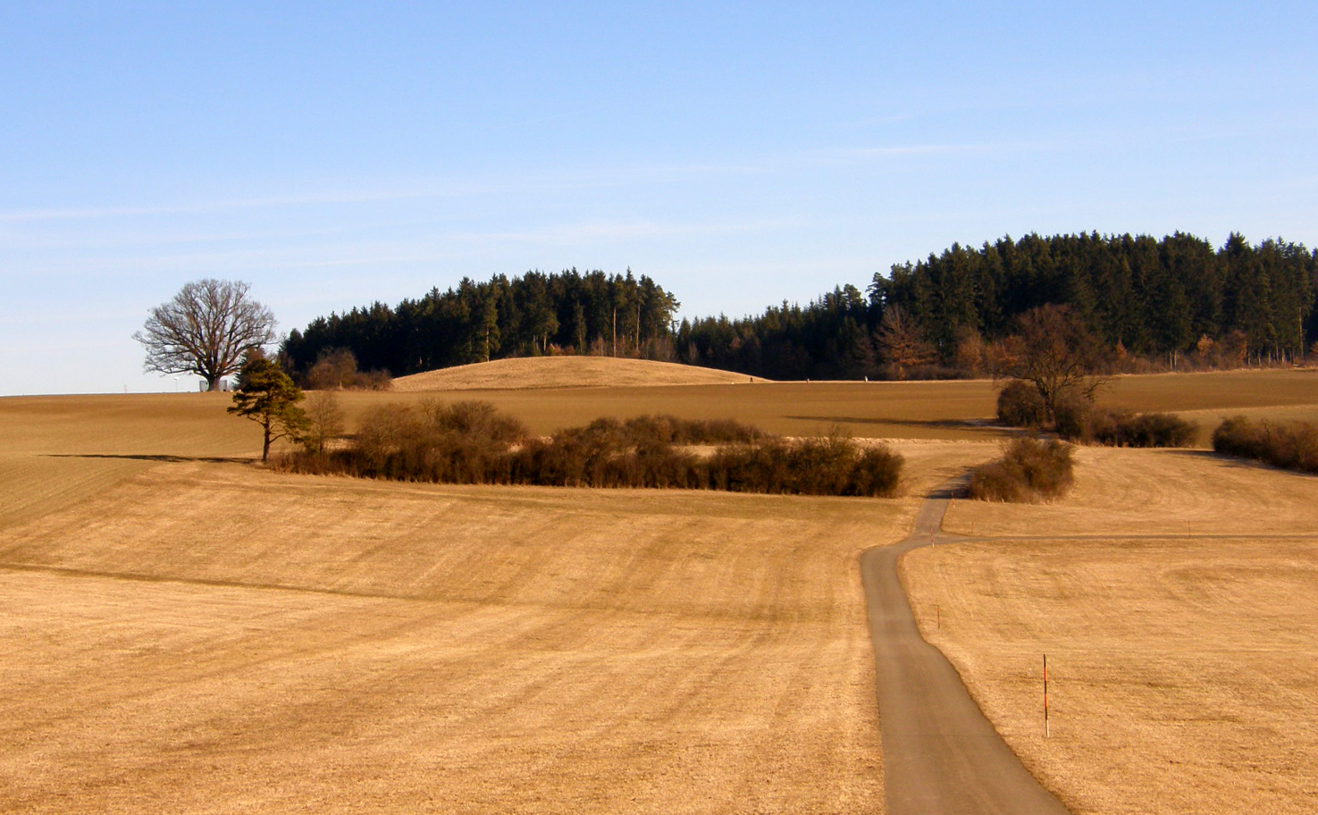
The "building":
The royal tomb at Magdalenenberg, near Villingen-Schwenningen, in Germany’s Black Forest, is the largest Hallstatt tumulus grave in central Europe, measuring over 320ft (100m) across and (originally) 26ft (8m) high. The royal tomb functioned as a lunar calendar and preserves a map of the sky at Midsummer 618 BC, the presumed date of the burial. The order of the secondary burials around the central royal tomb fits exactly the pattern of the constellations visible in the northern hemisphere at Midsummer in 618 BC, while timber alignments mark the position not of the sunrise and sunset but of the moon, and notably the Lunar Standstill. Lunar Standstills are marked in several ancient cultures (including sites in Colorado and Ohio), usually by standing stones that indicate the point where the moon seems to rise and set in the same place, instead of rising in one place and appearing to move across the sky to set in another.
As such the royal tomb at Magdalenenberg is the earliest and most complete example of a Celtic calendar focused on the moon. Following Caesar’s conquest of Gaul, the Gallic culture was destroyed and these types of calendar were completely forgotten in Europe.
http://www.world-archaeology.com/
See also: http://en.wikipedia.org/
The copter:
- A Hexacopter (Mikrokopter frame, APM 2.6) based on a design concept by Stehen Gienow.
The cameras:
- Canon Elph 110 HS, one converted to IR
The free open source image and 3D processing chain:
The open source Ground Control Station:
The flight:
- Flight altitude: 50m AGL
- Ground image resolution: 0.7cm
The Results:
- 3D point could before dense matching:
- Clipped 3D point cloud after dense matching (however, not the highest resolution possible):
You can download this file here (22MB *.zip).
- RGB orthophoto:
- IR orthophoto:
- Soil Adjusted Vegetation Index map:
- Digital surface model draped over a hill shade model and the IR orthophoto:
The georeferenced model
- Google Earth: T3_Magdalenenberg.kmz (with subfolders)
- including:
- Flight path
- Camera trigger locations
- RGB orthophoto
- IR orthophoto
- DSM model
- Size: 11MB
- including:
The 3D model to play with
- WebGL 3D model
- it might take some time to load...
- tested with Firefox, Chrome, IE and Safari (needs to be enabled)
- this is how it looks (in case it doesn't load)

A 3D visualization for some more serious analysis
- Orthophoto
- Hillshade
- Enhanced Vegetaion Index
The APM Log file:
Some random remarks:
- All data is georeferenced
- MicMac (as well as the whole processing chain) is quite complex
- Due to security reasons I always take off in stabilize mode
- Landing should have been automatic but needed to be interrupted due to some curious onlookers
- APM+Droidplanner is a great professional product
- It would be great to have an image dataset (or several) available on DIYDrones for comparing image processing software
- Color calibration is a big issue
Thanks to Gary, DIYdrones, 3DRobotics, and the developers of the free open source tools!
Thorsten

This is an old German bunker from WW2 fall on the beach at Sainte-marguerite-sur-mer, france. The fire services took down the blockhouse in 1995 because of safety concerns linked to cliff erosion.
If you want to know more about this blockhouse and the cliff :
Credits :
- Drone operator and photomodeling : Sylvain Herubel
- Ground station engineer and co-pilot : Raphael Bria
- Cameraman and Blender processing : Stephane Guillet
- Snow covered blockhouse : Julien Beaumel
It’s always the same setup, our little quad works very well for automatic flights

Config :
Quadricopter flameweel frame (X450)
ESC 30A simonK
Motors Sunysky X2212 980 kv prop : 10*5
RC T9X open9X - frsky 2.4ghz module
APM2 with GPS and compass onboard
Arducopter 3.1 RC5
Lipo 4S 3000mha
Video link : 200mw 5.8 ghz
Camera S100 with CHDK
Mobius camera with Sunnex lens (pictures from Mobius will not be used due to excessive rolling shutter)
Ground station with Asus 1005HA, 3DR 433mhz telemetry and extra deported 433mhz antenna
Total flight time : 3min40
Automatic flight : 3min
65 good aerial pictures from S100 and 20 ground photos from Lumix G3 are used to compose the model.
Video of the flight and worflow :
Short version, only results :
Here you can see 3D model on Sketchfab, if it appears black, juste wait for texture :

Blockhaus Sainte Marguerite sur mer from panormandic
Here you can download logs from APM2 and kmz flight path :
http://panormandic.com/blockhaus/logs&path.zip
Flight path :

Green : Auto mode
Red and grey : Stabilize (manual) mode
Yellow : Alt Hold
Orange and blue : Loiter
Garry, if you want to fly over the model with GEFS, just download this KMZ (it could take some time to load into GE) :
http://panormandic.com/blockhaus/Fallen_blockhaus.kmz
Orthomosaic :

DEM :

Virtuals renders :


Thanks for DIY drone and 3D Robotic for this contest.
Today i recived this mail , I would share it with the member of Dev Team , Thanks a lot :)
Hello,
It is with great pleasure that I send you this news.
There has been a project in Portugal in which an autonomous boat and hexacopter cooperate for monitoring of rivers. http://riverwatchws.cloudapp.net/
We just recently have been mentioned in Hack a Day http://hackaday.com/2014/01/30/riverwatch-an-autonomous-surface-aerial-marsupial-robot-team/
The hexacopter uses the VrBrain as it's controller, and some additional hardware. I thought you would be happy to know about this usage of the VrBrain and maybe help share it.
Thank you so much for reading and for all the work you have put into this.
Paulo Rodrigues
Thank you too Paulo and at your team for this great work :)
This is the Post on hackaday :)

Every once in a while we get a tip for a project that really, really, really blows our minds.This is one of them.
It looks like a basic catamaran with a few extra bells and whistles — except it is so much more than that. You’re looking at a fully Autonomous Surface Vehicle, complete with a piggybacking 6-rotor UAV. It’s decked out in cameras, sonar sensors, laser rangefinders, high accuracy GPS-RTK tracking, an IMU, oh, and did we mention the autonomous 6-rotor UAV capable of taking off and landing on it?
It all started out as a simple experiment within ECHORD (the European Clearing House for Open Robotics Development), and since then it has become a fully funded project atUNINOVA, a Centre of Technology and Systems in Portugal.
The purpose of the mind-blowing robot team is to collect data of river environments — think of it as Google Maps 2.0 — which is almost an understatement for what it is capable of.
You seriously have to watch the video after the break.
original blog post : http://www.virtualrobotix.com/profiles/blogs/vrbrain-hexacopter-in-european-project-autonomous-boat-and-hexaco
新年快乐. A happy Chinese New Year to all those who celebrate it, year of the horse!
"FPV Shaolin Returns" was filmed with a basic 1-axis ArduPilot Camera Gimbal RC10 (A10) which you can see on camera 2. This was a volunteer project featuring original music scores to launch the missing children banners.
Fun Facts: At marker 1:00 the arducopter dance was filmed to resemble the traditional lion dance that performs in front of a temple during Chinese New Year . The quadcopter lands and casts a shadow with the famous Shaolin's eagle stance, shown on marker 3:08
Blog: Gimbal Setup using Mission Planner: http://diydrones.com/profiles/blogs/ardupilot-camera-gimbal-setup-with-mission-planner
At the recent LCA'2014 conference in Perth I gave a couple of talks about research projects I'm working on with ardupilot. These show a couple of the things that we are working towards with APM.
The first is a talk on differential GPS which is part of a collaboration between Ben Nizette at ANU and myself.
Video:
https://www.youtube.com/watch?v=sl8aJlG52PE
Slides: http://uav.tridgell.net/LCA2014/dgps.pdf
The second talk is about the research project to run ardupilot directly on embedded Linux boards, which opens up some really interesting possibilities for APM:
Video:
https://www.youtube.com/watch?v=ealH3qP_pBE
Slides: http://uav.tridgell.net/LCA2014/AP_Linux.pdf
These projects are really just a small part of what we are working on, but I thought a few people might be interested in them.
Cheers, Tridge
Interview on The Register with Stuart Smith's ambitious project to build a three axis GoPro stabilized helmet cam that is not a bunch of crazy wires and poorly documented controllers.
And, by the end of 2013, a fair number of 3-axis gimbals were available from from China for R/C use. However, what they all have in common is:
- They are all pretty DIY looking things with wiring hanging off them everywhere. Usually the pictures don't show the wires, or the controller, so the end result looks like a rats' nest.
- They need setting up on a computer, which needs the user to know what they are doing, farting around with closed loop PID controls and the like.
- They are all for either handheld or R/C use, using potentially dangerous LiPo batteries.
This seems like an awesome product to complement RTF quadcopters like Iris
more info here http://www.theregister.co.uk/2014/01/29/stubilizer/
VRBrain 5.0 Light
The entry level revision of our new board . It's real DIY , cheap and affordable as 8 bit platform with the power of next gen autopilot technology , and a lot of great improvment . Keep in touch for more info ..
It support APM Copter, APM Plane and Rover in last revision.
VRBrain 5.0 NuttX O.S.
After 4 revisions of boards without full support for a Operating systems it's the time to fully support NuttX O.S. on VRBrain , ew features that are coming.
VRBrain 5.0 PRO
In Europe there are some country start to certify UAV technology for Commercial application , In USA in 2015 the market will be open . VRBrain 5.0 Pro it will be right platform for H2020 research project , Virtual Robotix will be technical support for develop affordable and powerfull UAV technology. Can Bus , Fault tolerant solutions , Advanced hybrid configuration ... a lot of impressive new opportunity to develop the UAV of your dreams.
These picture take yesterday in VRLAB the first RC1 VRBrain 5.0 is ready and under test ...
on our repo appear first release of code for the last revision of VRBrain Board ...
For more info about new product or H2020 research project send a mail to r.navoni@virtualrobotix.com
original blog post : http://www.virtualrobotix.com/profiles/blogs/secret-picture-takes-in-vr-lab-vr-brain-5-0-is-coming
I wonder what would happen if the whale breached and expelled ocean water from below the multirotor? Better bring the floats!
I've just released APM:Plane 2.78
This is a bug fix release for a number of important issues found in the 2.77 release.
The changes in this release are
Fixed sensor start-up on the APM1
I'm embarrassed to say that I didn't test the APM1 for the 2.77 release as my APM1 had died. It was a trivial fix, and the APM1 is working again in 2.78
Pixhawk Barometer fix
Fixed a potentially serious bug on Pixhawk if the board is flown in high temperature environments. If the board temperature gets above 65 degrees C then some boards would get bad barometric readings, thus giving bad altitude readings. This fix was a change in the GPIO settings on the SPI bus used to talk to the MS5611 barometer. Many thanks to Darrell Burkey for supplying the log file that found this bug.
Fixed LED behaviour on Pixhawk
The large 3 colour LED should now correctly display the failsafe and GPS status
Improved PX4 and Pixhawk compass calibration
We now run a strap calibration on every boot which improves compass accuracy by a small amount
Added RSSI_RANGE parameter
This allows you to scale your RSSI input to match your receiver
Fixed GPS health status in MAVLink
The GPS health bit will now show as unhealthy if the GPS does not have 3D lock. Thanks to Iskess for reporting this issue!
Also thanks to everyone who gave feedback on 2.77, much appreciated!
Issues with this release should be posted on the APM:Plane forum
ROS is primarily used by ground-based robots, but there is a user group here on DIY Drones who is exploring its use for drones, too. (Any Arduino-based platform can become a ROS node). Now there's a 101 tutorial for people are want to learn more about ROS.
From Hackaday
A robotics company called Clearpath Robotics — who use ROS for everything — have decided to graciously share some tips and tricks on how to get started with ROS 101: An Introduction to the Robot Operating System.
The beauty of the ROS system is that it is made up of a series of independent nodes which communicate with each other using a publish/subscribe messaging model. This means the hardware doesn’t matter. You can use different computers, even different architectures. The example [Ilia Baranov] gives is using an Arduino to publish the messages, a laptop subscribed to them, and even an Android phone used to drive the motors — talk about flexibility!
It appears they will be doing a whole series of these 101 posts, so check it out — they’ve already released numéro 2, ROS 101: A Practical Example. It even includes a ready to go Ubuntu disc image with ROS pre-installed to mess around with on VMWare Player!
From the Google Earth blog:
Around a year ago Paul van Dinther shared a cubic spline curve that identified a path through the Grand Canyon.
Colin Hazlehurst (who has created items such as Captain James Cook’s exploration of Australia) was working on software to animate model aircraft in Google Earth and thought it would be an interesting exercise to make his Spirit of St Louis model fly along Paul’s curve.
This KMZ file
shows this in action, and illustrates the following (in Colin’s words):
- The model moves in turn to each set of coordinates (longitude, latitude, and altitude) defining the LineString. The duration of each AnimatedUpdate is determined by calculating the distance between points and dividing this by the pre-set speed of the model.
- The roll and tilt of the model are calculated from the changes in heading and altitude respectively between successive pairs of coordinates.
- A Camera ‘follows’ the model with a pre-determined offset, defined in terms of heading, range, and tilt relative to the model. These values identify the location of the Camera, but the Camera also has a tilt setting which varies according to the pitch of the model; if the model is climbing, the camera tilt is reduced; if the model is descending the camera tilt is increased. This has worked fairly well in this instance, but I notice that at one point the Camera bounces off the wall of the canyon. This might happen when you view the kmz, and I would suggest trying different aspect ratios (width to height) of the Google Earth window.
I thought at first it wouldn’t look right to fly a model aircraft along a spline curve; it didn’t seem to be the way that aircraft flew. I realise now that this was because my first experiments drew splines on too large a scale, with many miles between interpolation points. Paul’s curve is on a much smaller scale, making for correspondingly small adjustments to the flightpath.

The cat may have inadvertently been let out of the satchel about UAS airworthiness and certification on twitter. There are also some indications that the small rule is being redrafted. Again, while these iterations are made the small business guy is sitting on the sideline. I have expressed multiple concerns over the years about any aircraft certification or pilot certification process that was too onerous for small business. I was assured that the small businessperson would be considered. However, there is concern as the “public” and small business stakeholder has not been part of the process for some time. Years have ticked by, and we have nothing to show for representation.
Occurrences like these of hiding information suggest that there is ample cause for concern and only further undermines the public trust in the UAS rulemaking process.
Lets hope this doesn’t mean that we need to start building Raven type aircraft. A petition is in the works to hopefully end the DoD vendor controlled, and apparent FAA sanctioned disenfranchisement of the “public” and small business end-user.
Developing
Late last year we released our first version NDVI converted cameras using Schott BG3 filters. Using those filters we were able to generate pseudo NDVI images with a single camera, building off the work of the Public Lab project. After working with faculty at the University of Boston and the MEASA Lab at KSU, we determined that we weren’t quite getting the best results possible with the BG3 filter glass. Unfortunately, no off the shelf filter glass seemed to do exactly what we needed, block out red light and allow NIR light to pass instead. Luckily, we were able to find a manufacturer to help us build a custom filter to our specifications, and the results are looking really good! Below are two images, the first taken by a camera with BG3 filter glass and the second taken by a camera with the new custom glass, the difference is clear.
BG3 Filter Glass
Custom Filter Glass
Aside from higher overall values, there is more differentiation and detail in the leaves and a larger difference compared to the non-organic background material. This is especially important for this type of camera. Since these are uncalibrated, pseudo NDVI images, what is really needed most is high differentiation so that comparisons can be made between the majority of plants and potential problem areas. The higher detail available now makes it possible to catch unhealthy plants sooner.
Custom Filter Transmittance vs Wavelength
The new filters will be priced at $39.99 for the filter alone (8.9×7.9mm, fits SX260 and S100 at least, potentially others) and$499.90 for a ready to go converted SX260 with CHDK. It’s a little cold to be doing any crop surveys here in the Northeastern US right now, I actually ended up killing those two plants after taking them outside for just a few seconds! We’ll be out and collecting imagery as soon as anything starts growing and I’ll post updates as they become available.
From the DJI Website HERE
DJI Product and Service Availability in North America
We would like to clarify that a recent temporary injunction limiting DJI’s ability to work with selected dealers in North America does not prevent these dealers from providing sales and support of DJI products to any of their customers, nor does it prevent dealers not identified in the temporary injunction from conducting normal business operations.
This legal action was taken by a former associate for issues linked to his recent departure from DJI. We are confident that the matter will be resolved soon.
DJI is a global firm and we are continuing to provide creators and innovators with first-class products and customer service support that has been the core of our business since our firm was established in 2006.
We are incredibly grateful for the support that we have received from our customers and will continue helping our customers in North America and beyond push forward the future of possible.
For further information please contact:
General Info: Info@DJI.com
U.S. Product Support: US.Support@DJI.com
Sales: Sales@DJI.com
Media Enquiries: PR@DJI.com
We value our customers in providing the best before and after sale experience. Despite our effort in offering the best service, support and warranty there are unauthorized sale channels offering quick sale with unsatisfactory after sale support. DJI continues to work with, and ensure our authorized dealers to offer after sale support and service to the highest standard. Purchases from unauthorized channels will void manufacture warranty; repair fee will be charged in addition to shipping cost.
This model includes a plethora of new features including:
• 2-axis brushless gimbal with optional pitch control
• 1080/30 camera with 720/30 video downlink to mobile devices
• 3S 3000 mAh flight battery for extended shoots
• New DX4 Transmitter
The 350 QX AP Combo also takes on a host of upgrades to the existing system including:
• New RF chipset with external antenna
• Improved GPS performance and accuracy
• Visual compass error detection to alert the user for calibration
• Simplified radio solution for ease of use
• Included AC/DC charging solution
• White battery hatch for improved orientation
Thanks Paul.
