All Posts (11086)

Sort by
3D Robotics

XL-MaxSonar-EZ use on a Multi-Copter

Thanks to Tom Bonar from Maxbotics for passing on this new post on how the best use their sonar sensors with mutlicopters. 

|     Written By: Bob Gross     |     DatePosted: 02-14-2013     |

MaxBotix Inc., sensors have been successfully used on a number of multi‑copters. Multi‑copters are also called UAVs, rotorcraft, quadrotor helicopters, or quadcopters. Many users have had issues getting the sensors to operate reliably. Sensor operation during flight on a quad‑copter is a challenging environment for an ultrasonic sensor to operate reliably. The most obvious issue is the amount of wind turbulence the ultrasonic wave must travel though. Adding to this acoustic noise is the noise the propellers generate.

Electrical energy that the motors use (with amps of current) typically share the same micro-controller, controlling both the flight and reading the sensors, so conducted electrical noise is likely. Also, amps of current are typically switched on and off rapidly, and common two‑way radios such as Zigbee, XBee, etc., are used, radiated electrical noise is also likely. Additionally, some multi‑copters can have vibration on the frame. Taken together, these issues are substantial, and correcting only one issue, while ignoring the others may not provide reliable operation.

Air Turbulence

Propellers cause a substantial amount of air turbulence, yet they do so in a predictable manner. Mounting the sensor directly in the prop wash should be avoided. Best operation and results will be obtained by mounting the sensor as far away from the propellers as possible. If using the sensor to measure the distance to the ground, typically the best place for mounting the sensor is under the frame and near the center of the airframe. The airframe is the component of the multi‑copter that supports the rest of the components such as the motors, APM, wiring, etc.

Measurements of a powerful electric copter showed that this effect caused the sensor's received signal energy to lower, sometimes by more than ten times! This type of issue is generally overcome by using our XL-MaxSonar-EZ type sensors, but with careful mounting, some have used our LV-MaxSonar-EZsensors with great success.

Visualize this effect. Place an ice‑cube in front of your eye and look though it. Sure you can see though the ice‑cube, but much of the light is directed to or from other places. The air turbulence acts in a similar manner to the path light takes through the ice cube, changing the direction and intensity of the acoustic wave in erratic ways.

Propeller Acoustic Noise

Propeller acoustic noise is very similar to air turbulence except that instead of changing the amount of energy the sensor actually detects, this affect adds additional outside acoustic energy to the sensor. Most of this noise originates at the propellers tip vortex region.

Measurements of a powerful electric multi‑copter showed that this affect can cause the most sensitive sensors, such as the EZ0, EZ1, and sometimes the EZ2 sensors of both the LV‑MaxSonar‑EZ and XL‑MaxSonar‑EZ, to sometimes false detect this noise. This detection can cause a lower range than normal to be reported. Again, with careful mounting, many users have found that any of our LV‑MaxSonar‑EZ or XL‑MaxSonar‑EZ sensors will operate well.

We recommend that the user avoids mounting the sensor in places where the sensor has a direct path to any propeller. If you can see the sensor looking past the propellers, then the sensor will hear this sound. For best mounting foam rubber can be used to block this path, the user can mount the sensor under the flight electronics, or a combination of the two can be used.

Visualize this effect. Place a flashlight beside your eye, but directed into your eye (please don't do this, but try to visualize this effect in your mind), and look beside it to a distant scene. You might make out some of the features, but much of the features are blurred in your vision from the additional light. The propeller noise acts in a similar manner to the air path, adding additional acoustic energy in erratic ways.

Grounding and Power

Power and ground on a UAV is shared with the control system and motors. An ultrasonic sensor is typically best powered from the same system that reads it, such as the control system. The wiring of these items can have a pronounced effect on the electronics in the system. The Analog to Digital Converter (ADC) on the control system can be severely degraded if either the power or ground supplying the ADC is noisy. This in-turn can cause a sensor to be read with many ADC counts of "noise" even though the sensor may have a noise free output.

067-StarPower-Ground-300px.jpgA "star" power and ground system is generally best. The "star" is setup using individual twisted pairs consisting of power and ground, where each item that uses power has its own twisted pair running from the power source, such as a battery pack, to the power input. In this system setup, each item has its own power and ground running back to the source. If one component has a high current draw, such as a motor, only that component will have it’s voltage reduced. This voltage reduction is due to resistance in the wiring. The item with the high current draw, along with the associated changes to both the power and ground, are isolated from all of the other items being powered. Many times only the ground is wired in a star. If only the ground is wired in a star, voltage drops from high current items will likely bleed through to the other lower current items in the system. Individual twisted pairs running from system power to each load is preferred and greatly recommended. For a diagram of star wiring, please refer to the image on the right.

067-DaisyChain-Ground-300px.jpgA daisy chain is typically not a recommended method to distribute power. In a daisy chain system, all power and grounds run from one item to the next, using a minimal amount of wiring. All of the items along the chain will interact with each other. In this system, a twisted pair of wires is not typically used, and there is not much regard to the amount of power or current each item uses. Sometimes this method of wiring is OK for grouping components with similar current draws together, but interaction between the connected components needs to be considered. Sensitive items, such as the controller and sensors, should be connected using the "star" wiring method. For a diagram of what a daisy chain looks like, please review the image on the left.

Conducted Electrical Noise

XL-Filter-200x81.jpgElectrical noise is generated when the quadcopter motors are driven. Many amps of current are used to drive the motors and will spike/droop the voltage levels on the ground and power lines on a quadcopter at the motor switching speed. Additionally, radios such as Zigbee, Xbee, MaxStream, NEXbee, etc. that transmit from the quadcopter can generate noise on the

voltage supply during transmit. This noise on the power supplied to the ultrasonic sensor may cause the sensor to operate improperly. A simple power supply filter will alleviate most of these issues. The RC filter kit such as the MB7961 Power Supply Filter has a 100uF capacitor, a 10 ohm, and 100 ohm resistor that when used will eliminate most conducted noise electrical noise from getting to our sensors.

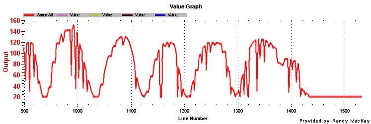
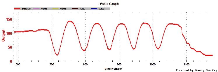
Many multi‑copters have solved most erroneous distance readings with this simple filter. The graphs below show a before and after pictures of the range readings without and with a power supply filter.

067-SonarSignal-WOF.jpg
The graph above shows the signal coming from a sensor on a multi-copter that has an unstable power supply.

067-SonarSignal-WF.jpg
The graph above shows the same sensor on a multi-copter after a power filter has been applied to an unstable power supply.

Radiated Electrical Noise

High switching currents used for driving the electric motors on quadcopters generate substantial amounts of radiated electrical noise. Additionally, radios that transmit from the quadcopter will always generate radiated electrical energy. This radiated energy acts as interference (noise) to other systems and sensors on the quadcopter.

Radiated electrical noise will generally not cause incorrect reading issues for our ultrasonic distance sensors, provided one uses the MB7961 Power Supply Filter. When users properly install a Power Supply Filter and use one of our digital interfaces, such as I2C, Serial, or Pulse Width outputs the sensor distance readings will typically not be corrupted by radiated electrical noise.

Users of the Analog Voltage Output from our sensors will likely have issues when using this sensor output in environments with radiated electrical noise, unless a shielded wiring harness is used. Our Shielded Cable, the MB7954 will work well for this. The shield on the cable must be properly grounded at the micro‑controller end. If the shield wire is not connected to the ground at the micro‑controller, the shield will do little or no good. The adjacent (-) ground pin beside the negative (- or ground) works well.

Measurements on a high powered quadcopter showed that the typical noise on the Analog Voltage Output increased from 10mV peak to peak to 260mV peak to peak when not using a shielded cable. When the shielded wire was used, and the motors at full power, the noise barely increased from 10mV to 12mV. Even with a shielded cable used and the shield wire was left floating (unconnected), the noise increased from 10mV peak to peak to 240mV peak to peak. It is important that the user ground the shield at the micro‑controller side only!

Frame Vibration

In addition to acoustic noise and radiated electric noise, frame vibration is also a possible source of noise for our sensors. This can be thought of as contact acoustic noise, where the energy from the frame is transmitted to the sensor. During our testing, noise from frame vibration was not observed on the powerful quadcopter we tested. This does not eliminate frame vibration might as a source of noise for other multi‑copters. Rubber washers, foam tape, or any other method that would eliminate frame vibration as a noise source are recommend.

Recommended Sensors

If you have a powerful quadcopter and would like to range the ground, MaxBotix Inc., recommends theMB1340, or the MB1240 XL-MaxSonar-EZ sensors. If you prefer using the I2C output, the recommended sensor is the MB1242.

Noise Source Cause Solution Comments
Air Turbulence Propeller wash over and around the sensor Mount the sensor as far from the propeller wash as possible. The most typical mounting location is to mount the sensor on bottom of the air frame near the center. Very common issue and sensor mounting position should always be considered.
Propeller Acoustic Noise Propeller noise into the sensor Mount the sensor as far from the propeller wash as possible. The most typical location is to mount the sensor on bottom of the air frame near the center. Very or most common issue and sensor mounting position should always be considered.
Grounding and Power Grounding and Power wiring isn't wired properly Wiring all components in a star Star wiring should always be considered.
Conducted Electrical Noise Conducted electrical noise from other items connected to the same electrical system. Use the Power Supply Filter Common issue and power supply filter is recommended for most users.
Radiated Electrical Noise Radiated electrical noise from other items near the same electrical system Use the Shielded Cable The shielded cable can improve sensor performance. If using the Analog Voltage Range Output from the sensor, the shielded cable is highly recommended.
Frame Vibration Air frame has mechanical vibration that is transmitted to the sensor. Mount the sensor using vibration isolating materials. Use rubber washers or foam.
 
Read more…
3D Robotics

New Hampshire considering aerial photography ban

3689505970?profile=original

FromAGBeat (via Hacker News)

New Hampshire bill proposes aerial photography ban

Neal Kurk (R), member of the New Hampshire House of Representatives since 1986 has recently sponsored HB 619-FN to make aerial photography illegal in their state, which many are considering a look into the future. States are currently struggling with how to deal with advances in drone technology, particularly mini-drones, fueled by fears not only that the federal government is using drones on U.S. soil, but are using them abroad not only to take out terrorists, but suspected terrorists, even if American.

Much media attention has been showered on the topic, bringing light to the full array of uses, not just the CIA’s implementation of the technologies. According to Fox News, the Federal Aviation Administration has already granted 327 licenses, and it projects as many as 10,000 licensed systems by 2017.

New Hampshire’s proposed aerial photography ban states the following:


"A person is guilty of a class A misdemeanor if such person knowingly creates or assists in creating an image of the exterior of any residential dwelling in this state where such image is created by or with the assistance of a satellite, drone, or any device that is not supported by the ground. This prohibition shall not apply where the image does not reveal forms identifiable as human beings or man-made objects. In this paragraph, “dwelling” means any building, structure, or portion thereof which is occupied as, or designed or intended for occupancy as, a residence by one or more individuals."

Potential problems with this bill

Although the bill seeks to protect residents from being spied on or documented, it very clearly excludes government officials who may use drones for official business. Most protests against drones are not against hobbyists, Google Maps satellites, or aerial photographers, rather against the government’s use of the devices.

The aerial photography ban is unclear as to the very specific non-threatening uses of aerial devices such as aerial real estate photography for listings, or if a homeowner is photographing their own home, and while it states that “This prohibition shall not apply where the image does not reveal forms identifiable as human beings or man-made objects,” possibly implying that if no human is in any photo or video taken, it is acceptable.

Additionally, it is unclear the implications of this bill on existing Google maps or existing images that have been taken via aerial device, and videography does not seem to be clearly addressed in the bill.

Fines for violations of a bill that could spread to other states

Rep. Kurk proposes a fine for violating the aerial photography ban, costing $62.71 per case in fiscal year 2014, rising to $64.40 per case thereafter, with an estimated $10,000 burden on taxpayers should someone appeal, and of course the $35,000 per year prison cost per person that fails to pay and is arrested.

Real estate photographer Larry Lohrman said, “Based on the public discussion that I’ve seen on this subject, I’m going to go out on a limb and make a wild guess and predict that this is not going to be an isolated incident. My guess is that other states will be doing this too. Particularly since so many cities are resisting use of UAVs by law enforcement.”


The full bill is here.

Read more…

linkall drone delivery

The Project linkall has been founded by Jiaqi Hu and Zebo Sun since Oct 2011. Linkall is considered to be the pioneer in the drones delivery system, which has been developed and researched by our team with all the curiosity and enthusiasm for such a new field.

The technological solution of fully automated end to end drones delivery system by linkall is not just a drone for transportation and delivery, but an totally autocratic and continuous working system. In the very near future, the convenient service provided by linkall will become an indispensable part of your life. Especially, we do not only provide service to urban residents, instead, we hope to serve all the people who need it with no charge, especially those in remote areas.

The making of

3689505867?profile=original

3689505684?profile=original

3689505892?profile=original

3689505910?profile=original

3689506002?profile=original

3689505921?profile=original

Our website:linkall.cc

follow us on twitter  @linkallcc

Read more…

Ground control station in the form of a tattoo!

3689505741?profile=original

Now we just have to think in MavLink!

From IO9

Temporary electronic tattoos could soon help people fly drones with only thought and talk seemingly telepathically without speech over smartphones, researchers say. Electrical engineer Todd Coleman at the University of California at San Diego is devising noninvasive means of controlling machines via the mind, techniques virtually everyone might be able to use.

Read more…
Moderator

3689505662?profile=original

Stefan a member of VirtualRobotix community from spain , doing a great job , one years ago send me first revision of openpilot revision of firmware for VRBrain. 

After some times of development yesterday , doing me a great news,  Stefan send me the VRBrain patch for TauLab project , a fork of openpilot project fully compatible with VRBRAIN.

He add the support of VRBrain directly inside the main code of autopilot and also inside the CGS as is possible to see in the screenshot.

He doing also first flight test :

this is the first video doing in indoor

and outdoor


The test is doing in a windy and cold days.

In this attachment you found the file for upgrade the bootloader of vrbrain and use TauLabs project.

You need to add the patch to original TauLab project here the code : https://github.com/TauLabs/TauLabs

This is the VR Brain Patch

https://code.google.com/p/vrbrain/downloads/detail?name=VRBrain-Tau-Labs.rar&can=2&q=#makechanges

Now the FoxTeam start to check the code and fly it , if some one interest to alfa stage of testing is welcome :)

Thanks a lot for your work Stefan !!! :)

Original Blog Post :http://www.virtualrobotix.com/profiles/blogs/not-only-arducopter32-on-vrbrain-now-is-available-also-taulab-pro

Read more…
100KM

The Techpods have landed!

img_20130225_124146.jpg?w=600

Wootwoot!

 They are here everyone!

That's a lot of techpods. I will start shipping tomorrow. Still have to work so the majority will be shipped Friday and Saturday when I will be having work parties with a few friend coming over for beer and pizza.

Thanks to the diydrones community for helping make this happen.

wayne

Read more…
Developer

Altium DXP version of APM 2.5 design

Hi All

I have just finished moving the design of the APM2.5v2 PCB to Altium AD13 and have attached it here. This will only work with the latest version of Altium (version 13)

the parts have been made into a library as well.

Please use the original EAGLE files as you primary reference, as I cannot be sure that I transferred everything correctly.

3689505487?profile=original

Read more…

Back At it

It has been a while but I am back at it . I made my first video the other day and with the help of Rainer Keller  and Chris Anderson  I finally figured out the path to post it on here to  show you guys. 

I Got a Midland XTC200 personal action cam strapped it to my Radian Pro and went flying . At my place on the farm there is a 150 foot cliff down to Lake Erie . The wind was blowing  30 knots up  over the cliff. (when you are eager to try something new,  sometimes reason takes the back seat !) I launched the plane,  about 100 feet up it caught the wind shear and was immediately blown 1/4 mile down wind."It was a Hand full"and I managed to land OK  right side up.

 Some of you guys might be wondering how my scratch built Aluminum air plane with the 32 EDF  turned out ? I assembled all the pieces and hung it from a rafter in the barn with the tail down and the nose up at full power it barely" hoovers " not  The performance I am looking for I want it to be able to climb straight up from stationary at half throttle . The Battery is way heavier than I had anticipated . (all you experienced guys can say "  Ha Ha I told You so!") My options are get a second EDF(make the same mistake twice) a Gas turbine or a 50cc Gas propeller engine . Meanwhile my radian pro is starting to show it's age I bought a Multiplex Easy Star a while back (box of foam) The radian is still flying down the road I am going to "Morph" The radian pro into the Multiplex  It is going to have an aluminum "Spine down the center joining the two haves together . You guys have a Great day!

Read more…
3D Robotics

Flying insects and robots

3689505611?profile=original

A great post from Sabine at Robohub:

TED just released an excellent talk (screenshot above; embedding isn't working) by Michael Dickinson from the University of Washington about how flies fly.

For years now, roboticists and biologists have been working together to understand how natural and man-made systems fly. We actually organized a conference on that topic in 2007 called Flying Insects and Robots, where Dickinson was one of the keynote speakers. The questions that most often arise are “how do you build a machine that flies” and “how do you control the behavior of these flyers”?

To tackle the first question, Dickinson’s lab built the Dynamically-Scaled Flapping Robot, or Robofly. The video below shows its assembly, but you can see it in action in his TED talk. The robotic model had a 60 cm wingspan, could flap around 5 times a second, and was immersed in 2 tons of mineral oil. By measuring instantaneous forces and flow patterns, his lab was able to explore aerodynamics of flapping flight.

To answer the second question, his lab uses high-tech fly arenas (fly-o-rama, fly-o-vision and rock-n-roll arena) that control the visual surrounding of the fly and record behavioral and neuronal activity. Insight gathered from such experiments, for example on how flies use optic flow to navigate an environment, have inspired a large number of robotic systems. Optic flow can be understood as the speed at which an image moves on the surface of your eye. If you’re in a car, looking at a distant mountain, the image of the mountain will move very little on your retina. If you are about to slam into a wall, the image of the wall will expand very rapidly. Large optic flow can tell you that an object is close. Optic flow is interesting for robots because it only requires very simple sensors (see Centeye sensor below) and processing.

The lab where I worked before at EPFL had lots of examples of how simple flying robots could use optic flow for 3D obstacle avoidance. The video below shows a flying wing that uses optic flow sensors found in your typical computer mouse to avoid the ground and obstacles.

Finally, going back to biology, one of Dickinson’s recent papers explores the reaction of real flies to moving objects, in this case a fly-sized robot (flyatar). Results showed that, similar to interactions between pairs of flies, walking female flies freeze in response to objects that move from back-to-front, wherease they ignore objects that move from front-to-back.

Here is a small video of the setup showing a flyatar tracking a fly, or being controlled by a joystick:

You can check Michael Dickinson’s lab website for more fly related material.

Read more…

Shhhh.... be vewy quiet, we're hunting Dwones!

I stumbled upon this... um... interesting video on Youtube.  Amazingly over 500,000 people have already watched it.  I think for the most part it's just some guys having fun with guns.  But it's another interesting insight into the growing fearmongering about domestic drones.

The statement that "The first person to shoot down a drone will be folk hero" is probably quite true I think.

Read more…

Easy to use FrSky-library for Arduino

20111221073704890.jpgFor my Control Station project, I also started writing a bunch of decoding function for the FrSky telemetry protocol.

I have now moved those functions into their own library for Arduino. My focus while writing and expanding this library is on ease of use. There is already Arduino code available but I found that a bit complicated to integrate. With the new library, all the user needs to do, is read one char from the serial port and send it to the library via the ::update method. All the decoding is done internally. The ::update method returns 1 when a complete packet was received, otherwise it returns 0. There is (will be) a dedicated method to access every parameter. I'll also try to keep up the detailled documentation.

At the moment, the library decodes only the basic information, RX A1 & A2 ports, uplink and downlink RSSI. Additional sensors will be included as I receive the hardware (which hopefully is soon).

Find the library at GitHub.

Example use (on MEGA 2560):

#include <frsky.h>
FrSky frsky;
void setup() {
Serial.begin(9600);
Serial2.begin(9600);
}
void loop() {
if (Serial2.available()) {
char c = Serial2.read();
if (frsky.update(c)) {
Serial.print("TX RSSI: ");
Serial.println(frsky.getLink_up());
Serial.print("Telemetry RSSI: ");
Serial.println(frsky.getLink_dn());
Serial.print("RX Voltage: ");
Serial.println(frsky.getRX_a1()*0.0517647058824);
Serial.print("A2 Voltage: ");
Serial.println(frsky.getRX_a2()*0.0129411764706);
}
}
}
Read more…
3D Robotics

3689505297?profile=originalYou may have noticed some slight design changes here over the past day, which are simply me band-aiding a situation where the external site that hosted some of our design files shut down, leaving a bunch of broken images and mangled CSS here. For now I've reverted to some native Ning design features and brought back an old header (above), but this strikes me as a good time to start the process of a proper redesign. 

In Spring, Ning (which we're hosted on) will roll out a bunch of new design and functionality features, which should improve things here considerably. It still won't perfect, especially for very long comment threads, so we're going to launch some new forums for product/software discussion/support on the new manual/wiki site that we'll be previewing in a few weeks. These new forums will be based on a very good WordPress forum plug-in, so they should be a big step up from what we've currently got. And by pushing product/technical support to a separate site, DIY Drones can focus more on its original function on news and discussion about civilian UAVs and technology in general. 

In the meantime, it's time to update our header. So I'd like to launch a competition for the best design. The winner will get an APM 2.5+.

Guidelines:

  • Create a rectangular graphic (width 955 1,000 pixels, height anything from 100 to 200 pixels) that will replace the above. 
  • The name should stay the same ("DIY Drones") but the tagline should change to "Amateur UAVs, Contests, Products and More" Revision: I've had advice to lead with "community", so let's try this: "The Leading Community for Amateur and Civilian UAVs" Another revision! After yet more advice, let's go with "The leading community for personal UAVs". You can use any style you think looks best (caps or lowercase).
  • There should be some image of a UAV. Ideally, it should look cool and "drone-like" but not look military or threatening. Fixed wing or multicopter, it's up to you.
  • Post your submissions in the comments below
  • The competition will run one month, until March 23rd

Last time we did this, back in 2010, we got some great submissions. I'm looking forward to seeing what the design talent in this community can come up with this time!

Read more…
100KM

Proposal to merge XFLR5 and PX4

120miles.jpg?w=774

(copied from my blog at hobbyuav.com)

Hey everyone!

I have not found a place where the fixed-wing control for the PX4 is being done so I started this blog.

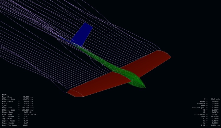
Above is a Screen shot from XFLR5. I use it to mathematically model the physical form of an airplane. I can then take this description of said plane and then start modeling the flow of air over the surfaces described is the model. You can then send modeled air at it in different angles and at different viscosity. In other words different pitches and yaws as well as different air densities or altitudes.

I use it all the time to make U.A.Vs. I think it should be integrated into the PX4 so that we can start introducing into the mathematical models of the control algorithms, a model of the crafts interaction with its environment (air).  Thus achieving a much more complete  mathematical description of the system.

This can be implemented by modeling the aicraft in XFLR5 then taking the results and generating LUTs of the predicted  air/air-frame interactions. just one example of this would be to use the generated full airplane polar graphs to predict what AOA at a given speed and air density, should produce level flight or even produce a desired vertical acceleration (climb or dive). This would greatly reduce the dependence on the PID loop to achieve a given altitude, making the system much more stable at a greater range of the aircrafts flight envelope.

This can also be applied to different control loops as well. yaw and roll control. It can also be applied to  every control surface as well. XFLR5 can generate tables of inertial moment data as well giving you a Cm polar. this can be calculated for various control surface angles. You can then  take the aerodynamic Cm data and combine it with a physical inertial model to do a full stability analysis. The output of the Cm and the inertial model data can then be feed in to the control loops to achieve desired rotational accelerations instead of purely relying on the PID loop. Giving the control loops a much wider dynamic range that is possible with just a PID loop.

high-alfa.jpg?w=560&h=325

Read more…

An Interview with Chris Anderson, CEO of 3D Robotics

I have a little blog about my experiences with quadcopters called OddCopter.com. I have been so impressed by the recent feature enhancements and popularity of the APM2.5+ platform that I wanted to track down Chris Anderson and see if he would do an interview for my blog. He graciously accepted and here are the results:

An Interview with Chris Anderson, CEO of 3D Robotics

I think the interview turned out great and contains some really interesting stuff. Please check it out if you get a chance.

I am fairly new to the DIYDrones community. I have only used the ArduCopter software via the MegaPiratesNG port running on a MultiWii Pro Board. I have a Naza, and when I had tried various open source projects in the past, the altitude hold feature didn't seem to measure up, However, I noticed the recent iterations MegaPiratesNG had huge improvements in Altitude Hold. I also setup and flew a few missions a while back. It was a little scary for me, but it worked great. This has gotten my really excited about getting the real thing and giving it a try! 

Britt

Read more…
3D Robotics

iPhone-controlled paper airplane

3689505317?profile=originalFrom Gizmag:

Earlier this month, we reported on the PowerUp 3.0 – a US$50 kit that lets you control a powered paper airplane via your smartphone. At the time, we were still waiting to hear back from its designer, regarding how a simple add-on motorized propeller could be used to actually steer the plane. Now we know.

To recap our previous article, the PowerUp 3.0 kit consists of a capacitor joined to a propeller by a carbon fiber shaft, that can be attached to a user-supplied folded paper airplane made from regular A4 or 8.5 x 11-inch copier paper. Using an iPhone equipped with Bluetooth 4.0 and PowerUp’s app, the user can then control the flight-path of that plane. But how?

As was suggested by some of our readers, the kit turns the plane via a small tail rudder, and climbs and descends via throttle control – this means that whenever it speeds up, it climbs, and whenever it slows down, it descends. According to creator Shai Goitein, the rudder is controlled simply by tipping the phone left or right.

“The really cool feature is the on-board accelerometer which gives the artificial horizon on the iPhone realtime airplane orientation, you can virtually fly it just by looking at your phone,” he added.

A PowerUp 3.0-enabled paper airplane can be seen in flight in the video below.

Read more…
Moderator

T3 season two, the multirotor one.

3689505259?profile=original

Its been a while so lets try again. Had a hangout with Chris and we briefly spoke about the next T3 round. Chris will work on a top prize ;-)

The mission is simple, get airborne climb to 20m 

Fly a cube with 50m sides, pausing for one minute at each corner, so your flight time cannot be anything less than 8 minutes..... Bonus points if you can stay longer at each corner....

The neatest cube KML wins.

If you can do this with a 3D aircraft I feel you would have a very strong chance of winning!

I will close the competition on April the 14th. I will be looking at where you are flying very closely. Please don't try this in public places or within 500m of any building / road. 

Read more…