All Posts (14049)

Sort by

3689506207?profile=originalThis is the third iteration of my Ardupilot Mega to Hitec telemetry adapter. Adapter no longer requires modifications to APM itself, but instead connects to telemetry port of APM and it has a pass through connector for telemetry transmitter. I made PCB this time using SMD parts for smaller size:

3689506434?profile=originalIt's possible to have the device automatically display different information based on airframe type. Currently shown vario and airspeed readings are not that useful for hexa, but for example heading might be. I just got my hexa so I've yet to decide what to show. Unfortunately compared to previous versions, it's not anymore possible to show "mAh used" reading since to my understanding that information is not sent in any mavlink message. When using different types of batteries, that information would be more useful than percentage remaining reading. Should we add mavlink message for it?

For more information about the device and sources, see http://antibore.wordpress.com/2013/02/28/showing-apm-telemetry-data-on-hitec-auroras-screen-3rd-edition/

Now if I only could get my hands on some different telemetry capable systems, I could try to make this adapter universal one...

Read more…
3D Robotics

UAV navigates by bouncing off walls and floors

3689506417?profile=original

From IEEE Spectrum:

A lot of UAV research is focused on making flying robots that can navigate by themselves using sophisticated sensor systems, intelligently avoiding crashing into things. This is a fantastic goal to have, but it's not easy. EPFL is doing away with just about all of that with a new version of AirBurr, a robot that's specifically designed to run into everything and crash all the time, building maps as it does so.

As we saw last June, AirBurr has undergone a remarkable evolution since 2009. And even in 2012, they were only on version 8, while the current version is up to 11. AirBurr is a coaxial UAV that is totally comfortable with collisions, thanks to its shock absorbing roll cage and self-righting mechanism:

Its rigid central core is surrounded by specially-designed tetrahedral-shaped springs that buckle to efficiently absorb impact energy. The springs protect the AirBurr from impacts with obstacles and can be used to physically interact with objects while in flight. If a collision results in a fall to the ground, the robot's Active Recovery System, comprised of a system of spring-loaded carbon fibre legs, allow it to return to an upright position and take off again.

Here it is in action:

Obviously, having just four sensors makes AirBurr kinda terrible at obstacle avoidance, but the simple fact is that it just doesn't matter: it may not be efficient at finding its way down a hallway, but it does so with an absolute bare minimum of sensors, and it wouldn't care if the hallway was pitch black or full of smoke or otherwise a place in which conventional vision would be out of luck. This vastly increases the number of environments in which AirBurr can be used.

The mapping behavior is especially cool, and if the resulting light paintings remind you of anything, it's because AirBurr employs a random direction algorithm that's similar to the one used by some robotic vacuum cleaners.

This sort of behavior is based in no small part on insects, which also have very primitive sensing systems combined with body structures that allow them to survive numerous collisions. Bugs may not be particularly smart, but as it turns out, big brains and complex sensors aren't always necessary for robust flight and navigation.

We'll see more of this research at ICRA in May from the EPFL team (which includes Briod Adrien, Adam Klaptocz, Kornatowski Przemyslaw Mariusz, and Zufferey Jean-Christophe), but there's a hint on EPFL's website as to where the researchers are taking this: they'll be presenting a paper entitled "A Perching Mechanism for Flying Robots Using a Fibre-Based Adhesive." Cool!

AirBurr ]

Read more…

What are some bullet points for DRONE interview.

bullet_point_stick_figure_point_med_image_500_clr.png?width=146

I am a member of the DC drone user group (200 strong). We are having a fly in this saturday and I will be interviewed by a media person concerning the use of drones. I don't want to mess this up as this is a politically volatile time for drones enthusiasts.  

What talking/bullet points would you include? What are the things that I will kick myself for not including after the interview is done?

• Benefits of drones

• potential good uses of drones

• future of drones

DIY DRONES COMMUNITY- please help. 

Read more…
3D Robotics

3689506378?profile=originalOn Sparkfun's Google Plus page, they've announced the new location of the annual Autonomous Vehicle Competition, which will be held on Saturday, June 8th in Boulder, Colorado. This year, in addition to cars and planes, they're readmitting copters, so the event has moved to a much larger area: the Boulder Reservoir. 

Also, for the first time, 3DR and DIY Drones will be organizing a day of drone education and hacking, called DroneCon, which will be held at the Sparkfun headquarters on Friday, June 7th. More details coming soon, but many of the DIY Drones developers and 3DR staff will be there, giving a day of tutorials on everything from drone control theory to communications and operations. For those who can't make it, it will be videoed to create the begninnings of a Drone Academy education program that we''ll be launching. 

More details on both AVC and DroneCon coming soon, but save the dates!

Read more…

PID Diagram for HefnyCopter - II Firmware

HefnyCopter2 implements full PID terms that is P, I & D. It uses the following approach.

3689506396?profile=original

My vision is to keep math as simple as possible and use superposition to accumulate different behaviors together based on my suggested framework.

Gyro values for balancing are in purple.

Accelerometer and accumulated Gyro are used together as a virtual angle device to get estimated Angle and implements the restoring function using a PID and are shown in green.

AccZ implements Positioning-Balancing and is shown in orange.

Sonar implements Positioning-Restoring and is shown in Red.


Please let me know how do you find this approach.


Read more…
Moderator

Click here to see a large version


Good evening to all,

today is an historic day for us, after 3 years from the birth of the Virtualrobotix.com community we finally founded the company VirtualRobotix Italia s.c.a.r.l. formed as a spin off of MpxLab Scarl a private research organization based at Kilometro Rosso of Bergamo (Italy).

Here is a photo of the toast ... Unfortunately, some of the members were not present but we expect in the next picture to be all.

We are 15 founding members (quite a number...) and others will join shortly and we are all driven by the will to transform their passion into a work.

Our mission is to facilitate the development of air, terrestrial and marine robotic technologies for the recreational, research and professional use.

We will take care of many things

  • inventing and developing new technologies made ​​in Italy and offering them to the world

  • training of pilots for professional applications

  • develop and certificate drones

  • Offer specific services as Aerial Video and Photography

And many other bound only by our imagination

The first public event of VRI will be at the “ModelExpoItaly” of Verona (2-3 March 2013) , where we will have a 36sqm booth!

If you need more info on how to join our initiative or need to know more details about our mission you can contact us at info@virtualrobotix.com

Greetings to all

Roberto Navoni


-----------------------------------------------------------------------------------


Buonasera a tutti,

oggi e' stata una giornata storica , dopo 3 anni dalla nascita della community Virtualrobotix.com oggi è nata la società cooperativa VirtualRobotix Italia Scarl , startup tecnologica ... costituita come spin off di MpxLab Scarl un organismo di ricerca privato con sede al Kilometro Rosso di Bergamo.
Ecco la foto del brindisi ... purtroppo alcuni dei soci sono dovuti scappar via subito dopo l'atto dal notaio .. contiamo nelle prossime foto di esserci proprio tutti 

I soci fondatori sono 15 un bel numero ... a breve se ne aggiungeranno ... mission della struttura agevolare lo sviluppo di tecnologie robotiche volanti terresti e marine sia nel settore ludico , della ricerca ed innovazione che nel settore professionale. 


Il primo evento pubblico di VRI sarà il ModelExpoItaly di Verona dove avremo uno stand !!!

Ci occuperemo di tante cose , dall'inventare e sviluppare nuove tecnologie made in italy e proporle al mondo , alla formazione di piloti per applicazioni professionali ,sviluppare droni certificati ecc ecc .

Da oggi esiste una realtà creata da tanti appassionati che hanno voluto fare della loro passione il loro lavoro 


se qualcuno vuole avere info per aderire alla nostra iniziativa o per conoscerne i dettagli ci puo' contattare ainfo@virtualrobotix.com

Un saluto a tutti
Roberto Navoni

Original : http://www.virtualrobotix.com/profiles/blogs/oggi-e-un-grande-giorno-nasce-virtual-robotix-italia

Read more…

My 1st Quad

3689506282?profile=original

I'm attempting my 1st quad build. I've been reading up on this for a very long time now and have finally jumped in. Cash is not always readily available, so I get my components small batches at time. Time is also quite an issue, so build small parts when and where I can.

Here is a parts list/pic

3689506101?profile=original

and my frame construction

3689506282?profile=original

Well that's what I got so far. I still need a radio and battery and also need to design/develop some landing gear.

I'm getting the ever popular HK 9X and thinking of 2600MAh 3S 30c battery.

Because this my 1st quad, I'm going for cheap controller boards, just to get the hang of it experiment with some frames etc. I will in the very near future get an APM!

Please tell me your thoughts

Read more…

What does a modular design do?

a modular design makes HeX adaptable from a quadcopter to a hexacopter even to a triple-rotor copter as the following picture shows

3689506187?profile=original

And also, we hope the modular design makes it friendlier to users because the complexity of putting a drone together is being brought down so that HeX is more accessible not just for hobbyists but also to more individuals in the future. 

Read more…

PX4 Coming soon to us all

The PX4 is here and soon it will have a fully supported version of ArduCopter:

3689505945?profile=original

From what I have been able to glean, Chris and Company are now in the process of revising this controller for better use by our group including an enclosure.

I Do not know for sure if they are planning on modifying the board itself but indications are that they are.

Now this is completely unsolicited by DIYDrones and may even be an annoyance to them, but there are some things I would like to see in there and I'll bet some of you would as well, so now is your chance to sound off before it becomes a fete acompli. 

Whether it will do any good or not I haven't got a clue.

An enclosure is good, but a internally vibration damped enclosure that was truly effective for reducing Accel vibrations to a fully tolerable level would be great.

Also, the existing PX4 pretty much requires that you use a PPM-Sum receiver with it.

PPM-Sum receivers are great, but only a few are available (Futaba and FR-Sky) not counting Graupner for obvious $$$$ reasons.

Personally I would like to use my plain old vanilla Hitec Aurora 9 and I think a lot of people would be a bit put off by having to upgrade their whole radio system because they didn't want to include a few extra RC inputs.

That's the 2 biggies I can think of, this is the place to put in your thoughts and we can see if anyone is listening.

This feedback is certainly unsolicited, I hope it is not also unwelcome.

Read more…

Techpod Build Video 1

Here's the first in the series of build videos that I am going to be doing on the techpod. 
i'm gonna wait for the camera to charge then it's time to get building the wing!

Read more…
Moderator

VR Brain at the "Palais de la découverte"

Hi everybody,

The project "ArdUFO : un drone au service de tous" was selected during the December holidays for being presented at the "Palais de la découverte" at Paris, on February 9th 2013, as part of the "Olympiades de Physique France" contest. 3689506130?profile=original

The UAV was created thanks to Roberto Navoni and his magnificent card : VR BRain !

The day ended with the awards ceremony. After some speeches of the selection board, the awards were finally released, and we finished with a second price !

We now decided to continue with the C.Génial contest, to perform our project.

You can follow us on our website : http://ardufo.funpic.org


Best

The ArdUFO project


original blog post by  Chydra : http://www.virtualrobotix.com/profiles/blogs/vr-brain-at-the-palais-de-la-d-couverte

Read more…

Open-Source Cars

osi_standard_logo.png

Something has been running through my head and I want to see what other people think. Am I the only one crazy enough to really want an open-source automobile? My background is in automotive, and I can see ardu-based (or something similar) hardware and software being easily integrated to cars. I just saw a Wired article on 3-D printing a car, and it got my brain spinning even more. Any ideas?

Clearly oil and auto manufacturers would hate the idea and do everything in their power to shut it down, such as the story of General Motor's EV-1 in the early 1990's.

Wired article is here:

http://www.wired.com/autopia/2013/02/3d-printed-car/?cid=co6071424

EV-1 information is here:

http://en.wikipedia.org/wiki/General_Motors_EV1

Read more…

APM, Robot Operating System (ROS) and the Kinect

Hi all - I just wanted to talk about a project I've been working on for school lately.  I am interfacing ROS with the APM and a Kinect Sensor (over MAVLink) to provide target tracking and attitude settings to the APM.  Here is a video of this working:

The wiki and all code for this project can be found here:  https://code.google.com/p/icarus-uav-system/wiki/ROS_APM_KINECT

Read more…
Developer

Probably the best GCS PC out there.

Xv01-08_17-48-4920_large_verge_medium_landscape.jpg

Starting at $999 for the Core i5-equipped, 64GB variant, the Razer Edge isn't cheap, but Razer doesn't seem to have skimped on quality. There's an Nvidia GPU inside it, beefing up the graphics, the base spec features 4GB of RAM (maxing out at 8GB on the Edge Pro), and though the screen resolution is only 1366 x 768, the display looks to be of a decent quality. Look for the Razer Edge to arrive in Q1 of this year, alongside the $249 gamepad dock and $99 docking station, with its keyboard dock coming up in the latter half of 2013.

http://www.theverge.com/2013/2/26/4032270/razer-edge-windows-8-tablets-available-for-preorder-march-1

http://www.razerzone.com/gaming-systems/razer-edge-pro

Read more…

AR Drone 2.0 teardown


ardrone13.jpg


For all the talk of the drone revolution, there remanes but 1 vehicle which is truly a plug & play drone for the masses: the AR Drone.  In true dot com tradition, ifixit.com made zillions of dollars in venture capitol & never did a teardown of the 2.0, so it was time for the unemployed masses to step in.


ardrone01.jpg

The entire electronics assembly & battery are supported by a piece of foam.  The boards still have many wires connecting to the frame, subjected to the full vibration.

ardrone06.jpg

A common 640x480 camera does the optical flow & seems to send some kind of compressed data.  It may be a 30fps USB cam.

ardrone07.jpg

A custom AR Drone sonar circuit.


ardrone02.jpg

ardrone03.jpg

It's a mane brain board & sensor board, connected by

ardrone04.jpg

just 8 pins.  The 2 cameras connect to the mane board.  The front cam may output uncompressed data.

ardrone05.jpg

A common PIC serializes the data from all the sensors.  Maybe it also fuses the sensor data.

ardrone08.jpg

The air pressure sensor is under a piece of foam designed to not touch it.

ardrone09.jpg


Standard gyro + accelerometer chip & unknown magnetometer, not that it matters since everyone is going to use the mpu9250 tomorrow.


ardrone10.jpg

The radio

ardrone11.jpg

with a trace antenna.

ardrone12.jpg


Under the can, it's a power management & USB chip from TI, some kind of flash & RAM from Micron.  In usual modern fashion, the mane processor would be sandwiched under the big chip, so there would be no way to see it.


The 1st test ever done to see how accurately the optical flow holds its position. Over carpet, it's hopeless & seeks the nearest line. With a target, it's decent at the default altitude, but slips off at higher altitude. As soon as it slips over carpet, the altitude reading goes high & it descends. It could be improved with more software.
Read more…
3D Robotics

XL-MaxSonar-EZ use on a Multi-Copter

Thanks to Tom Bonar from Maxbotics for passing on this new post on how the best use their sonar sensors with mutlicopters. 

|     Written By: Bob Gross     |     DatePosted: 02-14-2013     |

MaxBotix Inc., sensors have been successfully used on a number of multi‑copters. Multi‑copters are also called UAVs, rotorcraft, quadrotor helicopters, or quadcopters. Many users have had issues getting the sensors to operate reliably. Sensor operation during flight on a quad‑copter is a challenging environment for an ultrasonic sensor to operate reliably. The most obvious issue is the amount of wind turbulence the ultrasonic wave must travel though. Adding to this acoustic noise is the noise the propellers generate.

Electrical energy that the motors use (with amps of current) typically share the same micro-controller, controlling both the flight and reading the sensors, so conducted electrical noise is likely. Also, amps of current are typically switched on and off rapidly, and common two‑way radios such as Zigbee, XBee, etc., are used, radiated electrical noise is also likely. Additionally, some multi‑copters can have vibration on the frame. Taken together, these issues are substantial, and correcting only one issue, while ignoring the others may not provide reliable operation.

Air Turbulence

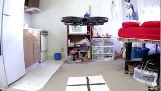
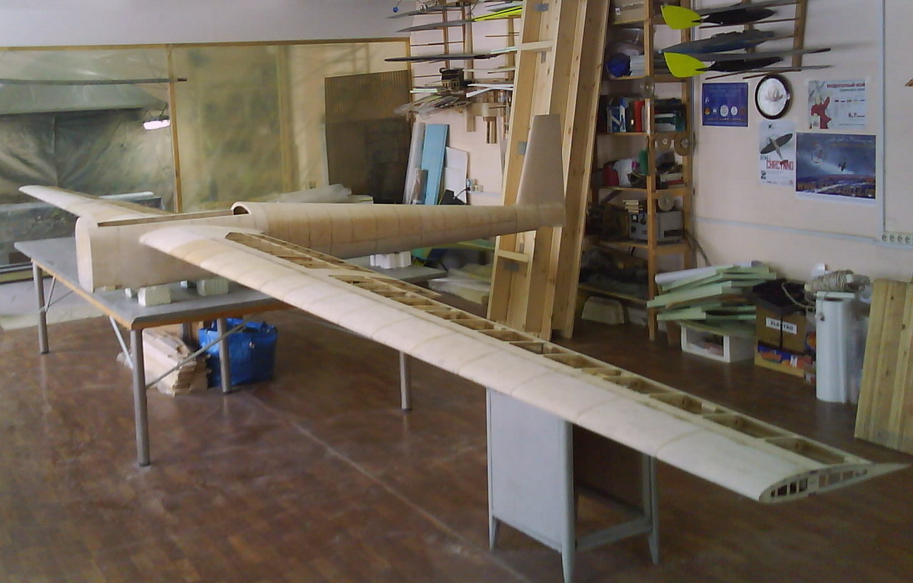
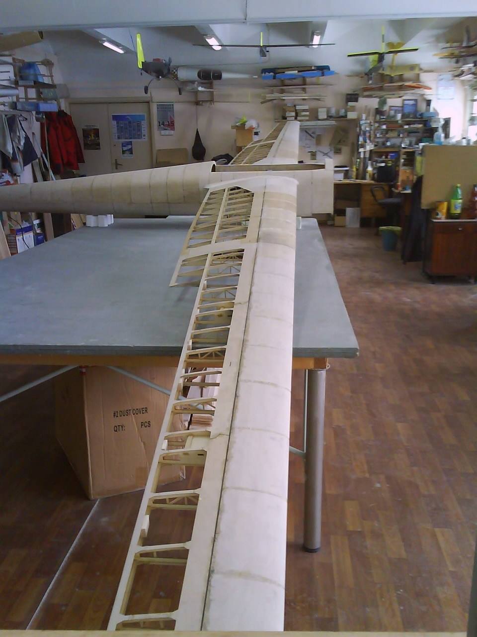
Propellers cause a substantial amount of air turbulence, yet they do so in a predictable manner. Mounting the sensor directly in the prop wash should be avoided. Best operation and results will be obtained by mounting the sensor as far away from the propellers as possible. If using the sensor to measure the distance to the ground, typically the best place for mounting the sensor is under the frame and near the center of the airframe. The airframe is the component of the multi‑copter that supports the rest of the components such as the motors, APM, wiring, etc.

Measurements of a powerful electric copter showed that this effect caused the sensor's received signal energy to lower, sometimes by more than ten times! This type of issue is generally overcome by using our XL-MaxSonar-EZ type sensors, but with careful mounting, some have used our LV-MaxSonar-EZsensors with great success.

Visualize this effect. Place an ice‑cube in front of your eye and look though it. Sure you can see though the ice‑cube, but much of the light is directed to or from other places. The air turbulence acts in a similar manner to the path light takes through the ice cube, changing the direction and intensity of the acoustic wave in erratic ways.

Propeller Acoustic Noise

Propeller acoustic noise is very similar to air turbulence except that instead of changing the amount of energy the sensor actually detects, this affect adds additional outside acoustic energy to the sensor. Most of this noise originates at the propellers tip vortex region.

Measurements of a powerful electric multi‑copter showed that this affect can cause the most sensitive sensors, such as the EZ0, EZ1, and sometimes the EZ2 sensors of both the LV‑MaxSonar‑EZ and XL‑MaxSonar‑EZ, to sometimes false detect this noise. This detection can cause a lower range than normal to be reported. Again, with careful mounting, many users have found that any of our LV‑MaxSonar‑EZ or XL‑MaxSonar‑EZ sensors will operate well.

We recommend that the user avoids mounting the sensor in places where the sensor has a direct path to any propeller. If you can see the sensor looking past the propellers, then the sensor will hear this sound. For best mounting foam rubber can be used to block this path, the user can mount the sensor under the flight electronics, or a combination of the two can be used.

Visualize this effect. Place a flashlight beside your eye, but directed into your eye (please don't do this, but try to visualize this effect in your mind), and look beside it to a distant scene. You might make out some of the features, but much of the features are blurred in your vision from the additional light. The propeller noise acts in a similar manner to the air path, adding additional acoustic energy in erratic ways.

Grounding and Power

Power and ground on a UAV is shared with the control system and motors. An ultrasonic sensor is typically best powered from the same system that reads it, such as the control system. The wiring of these items can have a pronounced effect on the electronics in the system. The Analog to Digital Converter (ADC) on the control system can be severely degraded if either the power or ground supplying the ADC is noisy. This in-turn can cause a sensor to be read with many ADC counts of "noise" even though the sensor may have a noise free output.

067-StarPower-Ground-300px.jpg
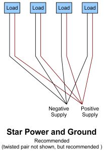
A "star" power and ground system is generally best. The "star" is setup using individual twisted pairs consisting of power and ground, where each item that uses power has its own twisted pair running from the power source, such as a battery pack, to the power input. In this system setup, each item has its own power and ground running back to the source. If one component has a high current draw, such as a motor, only that component will have it’s voltage reduced. This voltage reduction is due to resistance in the wiring. The item with the high current draw, along with the associated changes to both the power and ground, are isolated from all of the other items being powered. Many times only the ground is wired in a star. If only the ground is wired in a star, voltage drops from high current items will likely bleed through to the other lower current items in the system. Individual twisted pairs running from system power to each load is preferred and greatly recommended. For a diagram of star wiring, please refer to the image on the right.

067-DaisyChain-Ground-300px.jpg
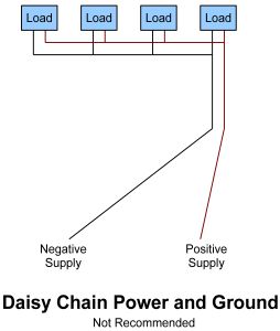
A daisy chain is typically not a recommended method to distribute power. In a daisy chain system, all power and grounds run from one item to the next, using a minimal amount of wiring. All of the items along the chain will interact with each other. In this system, a twisted pair of wires is not typically used, and there is not much regard to the amount of power or current each item uses. Sometimes this method of wiring is OK for grouping components with similar current draws together, but interaction between the connected components needs to be considered. Sensitive items, such as the controller and sensors, should be connected using the "star" wiring method. For a diagram of what a daisy chain looks like, please review the image on the left.

Conducted Electrical Noise

XL-Filter-200x81.jpgElectrical noise is generated when the quadcopter motors are driven. Many amps of current are used to drive the motors and will spike/droop the voltage levels on the ground and power lines on a quadcopter at the motor switching speed. Additionally, radios such as Zigbee, Xbee, MaxStream, NEXbee, etc. that transmit from the quadcopter can generate noise on the

voltage supply during transmit. This noise on the power supplied to the ultrasonic sensor may cause the sensor to operate improperly. A simple power supply filter will alleviate most of these issues. The RC filter kit such as the MB7961 Power Supply Filter has a 100uF capacitor, a 10 ohm, and 100 ohm resistor that when used will eliminate most conducted noise electrical noise from getting to our sensors.

Many multi‑copters have solved most erroneous distance readings with this simple filter. The graphs below show a before and after pictures of the range readings without and with a power supply filter.

067-SonarSignal-WOF.jpg
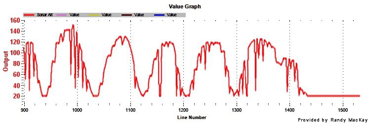
The graph above shows the signal coming from a sensor on a multi-copter that has an unstable power supply.

067-SonarSignal-WF.jpg
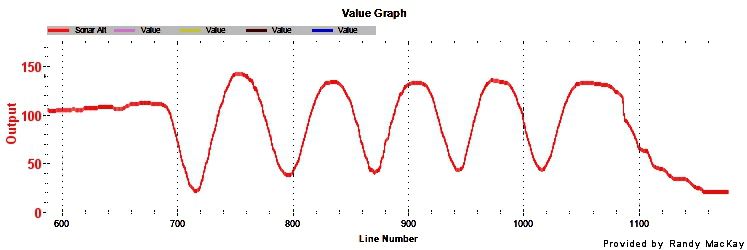
The graph above shows the same sensor on a multi-copter after a power filter has been applied to an unstable power supply.

Radiated Electrical Noise

High switching currents used for driving the electric motors on quadcopters generate substantial amounts of radiated electrical noise. Additionally, radios that transmit from the quadcopter will always generate radiated electrical energy. This radiated energy acts as interference (noise) to other systems and sensors on the quadcopter.

Radiated electrical noise will generally not cause incorrect reading issues for our ultrasonic distance sensors, provided one uses the MB7961 Power Supply Filter. When users properly install a Power Supply Filter and use one of our digital interfaces, such as I2C, Serial, or Pulse Width outputs the sensor distance readings will typically not be corrupted by radiated electrical noise.

Users of the Analog Voltage Output from our sensors will likely have issues when using this sensor output in environments with radiated electrical noise, unless a shielded wiring harness is used. Our Shielded Cable, the MB7954 will work well for this. The shield on the cable must be properly grounded at the micro‑controller end. If the shield wire is not connected to the ground at the micro‑controller, the shield will do little or no good. The adjacent (-) ground pin beside the negative (- or ground) works well.

Measurements on a high powered quadcopter showed that the typical noise on the Analog Voltage Output increased from 10mV peak to peak to 260mV peak to peak when not using a shielded cable. When the shielded wire was used, and the motors at full power, the noise barely increased from 10mV to 12mV. Even with a shielded cable used and the shield wire was left floating (unconnected), the noise increased from 10mV peak to peak to 240mV peak to peak. It is important that the user ground the shield at the micro‑controller side only!

Frame Vibration

In addition to acoustic noise and radiated electric noise, frame vibration is also a possible source of noise for our sensors. This can be thought of as contact acoustic noise, where the energy from the frame is transmitted to the sensor. During our testing, noise from frame vibration was not observed on the powerful quadcopter we tested. This does not eliminate frame vibration might as a source of noise for other multi‑copters. Rubber washers, foam tape, or any other method that would eliminate frame vibration as a noise source are recommend.

Recommended Sensors

If you have a powerful quadcopter and would like to range the ground, MaxBotix Inc., recommends theMB1340, or the MB1240 XL-MaxSonar-EZ sensors. If you prefer using the I2C output, the recommended sensor is the MB1242.

Noise Source Cause Solution Comments
Air Turbulence Propeller wash over and around the sensor Mount the sensor as far from the propeller wash as possible. The most typical mounting location is to mount the sensor on bottom of the air frame near the center. Very common issue and sensor mounting position should always be considered.
Propeller Acoustic Noise Propeller noise into the sensor Mount the sensor as far from the propeller wash as possible. The most typical location is to mount the sensor on bottom of the air frame near the center. Very or most common issue and sensor mounting position should always be considered.
Grounding and Power Grounding and Power wiring isn't wired properly Wiring all components in a star Star wiring should always be considered.
Conducted Electrical Noise Conducted electrical noise from other items connected to the same electrical system. Use the Power Supply Filter Common issue and power supply filter is recommended for most users.
Radiated Electrical Noise Radiated electrical noise from other items near the same electrical system Use the Shielded Cable The shielded cable can improve sensor performance. If using the Analog Voltage Range Output from the sensor, the shielded cable is highly recommended.
Frame Vibration Air frame has mechanical vibration that is transmitted to the sensor. Mount the sensor using vibration isolating materials. Use rubber washers or foam.
 
Read more…

Hello,

 Our first version of the arducopter has evolved and "MUGEN Mk II" now has some quite robust (although heavy) landing gear!

P1030706.jpg?width=640


I've set up some pages to share some details about both versions: here for the first version, and here for MUGEN Mk II.

This includes the blueprints for the custom laser cut parts, some photos, and a power benchmark for the jDrones motors, ESC and props along with the different Lipo I had in stock:

power-bench-MUGEN.png?width=641

We made some videos too!

Here is a first video (in french only, sorry!) to introduce our quadcopter:

And here's another one showing MUGEN Mk II flying in the french Alps!


Have fun! (^_^)

Nicolas


Read more…