For their P&O project, engineering students from the Belgian university KULeuven, designed and built multicopters. Because budget was limited, they chose for multiwii copters.
More info : http://www.mtm.kuleuven.be/Onderwijs/PandO32011/PandO32011
For their P&O project, engineering students from the Belgian university KULeuven, designed and built multicopters. Because budget was limited, they chose for multiwii copters.
More info : http://www.mtm.kuleuven.be/Onderwijs/PandO32011/PandO32011
Latest Progress from the Folks at the GRASP Lab
Would love to see what flight control algorithm they're using on these things.
Great picture of the infrared lamps, at the end of the video:


After receiving much attention over the past few days, the aforementioned Eye3 Drone project on Kickstarter has been officially pulled on account of photoshop shenanigans and overall shadiness.
From IEEE Automation Blog:
"At first glance, the eye3 drone seemed like an incredible deal. For US $2500, you could get yourself a beefy hexacopter capable of lifting over 6.8 kilograms (15 pounds) with an included autopilot that would take all of the hassle and stress out of flying the UAV...
People on the Internet, being people on the Internet, did some digging and found out several things. First, the pictures of the kit on Kickstarter are just pictures of this kit (from cnchelicopter.com) with the attribution photoshopped out. Also, the founders of eye3 allegedly owe a bunch of people money (or a product) on another project."
HobbyKing's done it again. Check out this deal: their mini-quad with four motors for $33.95! (Or $31.95 if you just let your browser sit open on that page for a few minutes).
All you need to add to make a RC quad (in addition to your regular RC system and LiPo batteries) is:
That's $90 all told. Now, in fairness, this is a pretty crappy little frame and it won't last past a crash or two. I also wouldn't expect too much outside in the wind. But what a great way to get started!
A feature frequently requested is to add support to ArduPlane for using sonar to control the landing flare.The answer, unfortunately, is probably no. Take a look at this graph I obtained yesterday...
This has been on my to-do list for ages as I have never gotten around to getting some real world data to see if this would work. Finally got the real world data yesterday with the Maxbotix XL-EZ1 mounted in a SkyFun.
The graph shows data logged on a flight with 6 low passes using APM2 and the MaxBotix . The standard ArduPlane/ArduCopter sonar library was used, including the 6 element mode filter (as recommended by MaxBotix. The terrain over which the flight was flown was middle of the road in terms of difficulty for the sensor (in my estimation) being open arid prairie, with scattered clumps of low prairie grass Based on the actual low passes the "good" altitude estimates (bottoms of the troughs) by the sonar were probably better than the equivalent altitude estimates by the baro sensor. Unfortunately, as can be seen, when moving over the ground with significant speed the sonar fails to maintain a clean estimate of the altitude, even with the mode filter.
Of particular concern would be occasions such as during the second, fourth, and sixth pass, where the sonar suddenly reports a much higher altitude than actual. If using sonar for flare control, this would likely result in a pitch down, with bad results.
Certainly under good conditions the sonar could be used for flare control, but it does not appear to give a robust enough estimate of altitude to be useful for general use.
A 3x2 propeller, another tuning of the PID & azimuth, & a lot of camera flashes got it up to 9 minutes. Previously, it was a 3x3 propeller. The motor stayed just cool enough.

Here, the battery hit 6.6V & started falling over. Throttle started ramping up at that point.
Overheating still sometimes happens faster & it shows up as a throttle which diverges from battery voltage.

Here, the battery never fell over but was stable at 6.8V. Throttle ramped up anyways, probably from motor overheating.

as hardware from 2 years ago is recycled


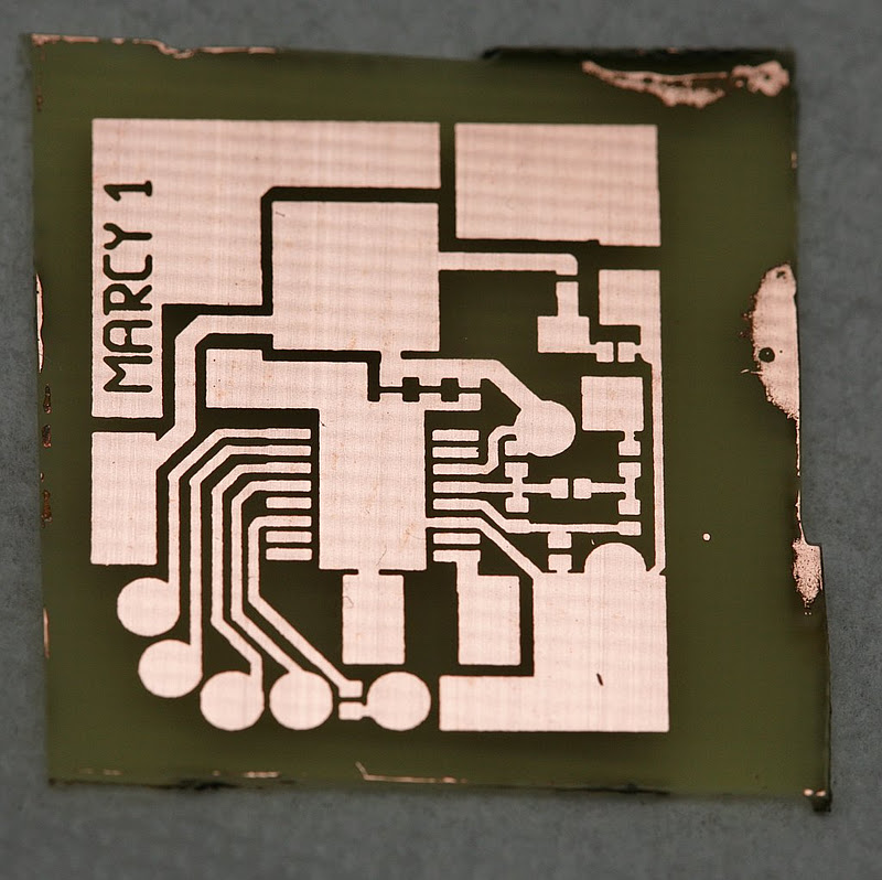

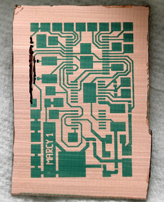
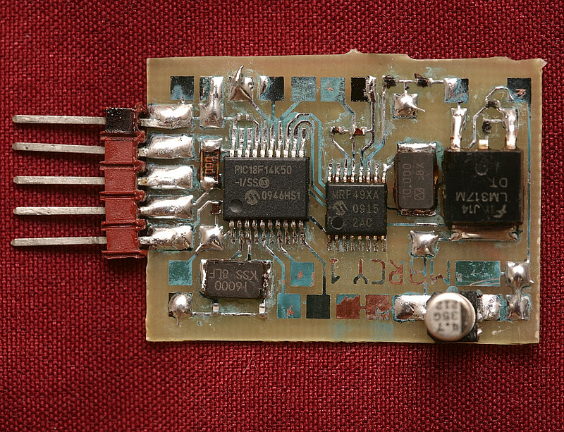


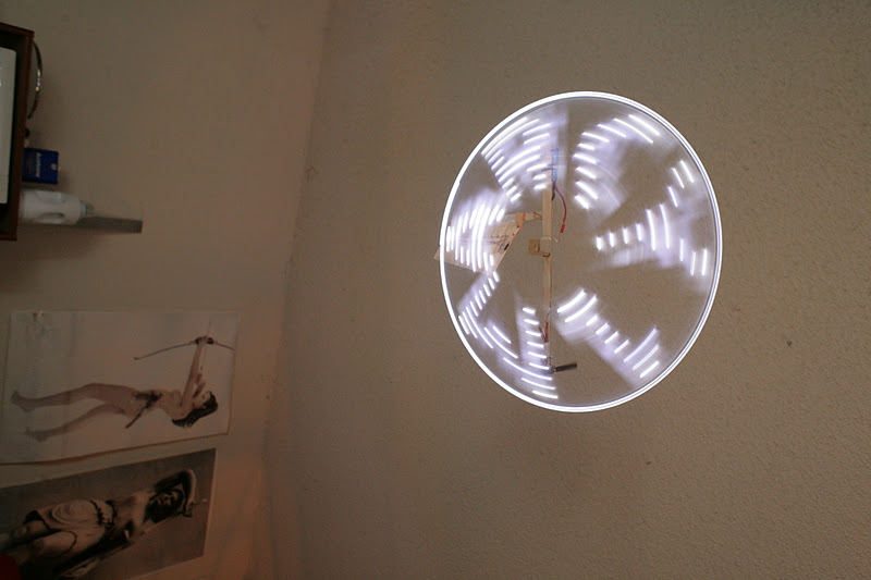
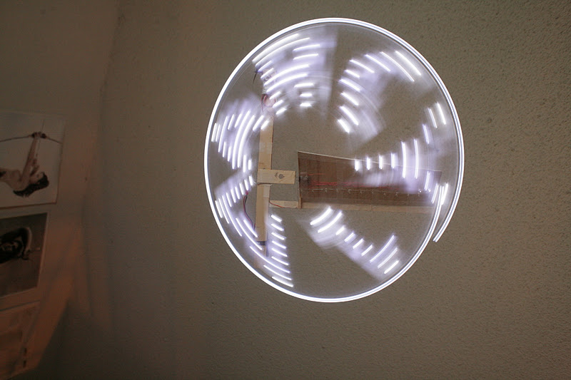
Disappointing that we never found a use for 3D sonar. Only a large blimp or a ground vehicle could have used it. Sonar overall is a mess. We once envisioned a network of receivers on a ceiling, allowing a UAV to travel anywhere in a building. It was way too directional & slow.


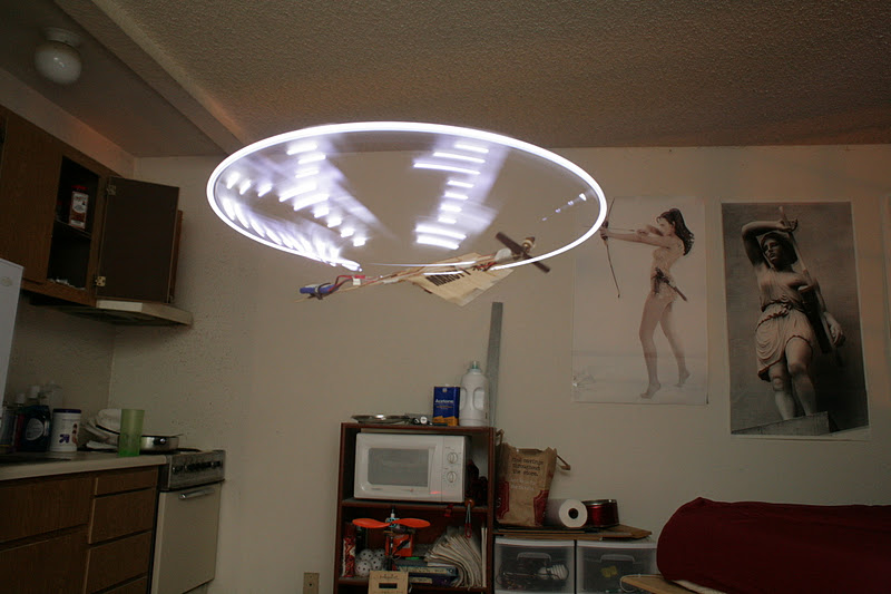
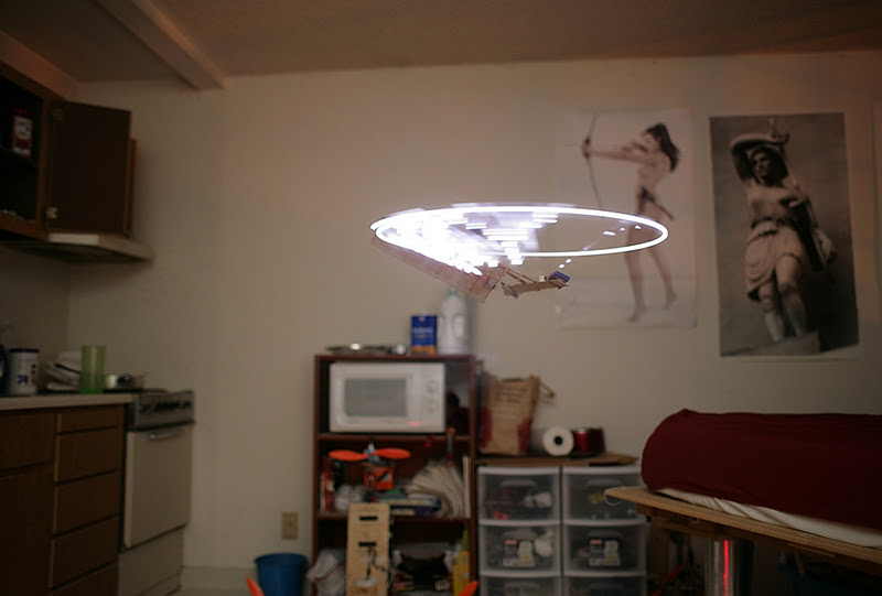


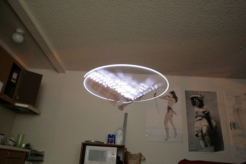


There was also this video of the very 1st POV flights, with lousier tuning.
Sorry for the video quality, but the slr was tied up :)
Finally finished the universal IR camera shutter release device.
The requirements were:
1. Remotely trigger the camera to take 3 photos in a row using a switch on the transmitter.
2. A solution that doesnt involve a physical connection to the camera, as my shutter release port on my Nikon is taken up with a GPS geotagger cable.
3. A universal trigger that will work with most cameras that have IR shutter releases.
What I put together:
An Arduino Uno based MCU that has specific libraries by Sebastian Setz for IR communication for cameras.
A super simple code. Involving nothing more than a shutterNow(); to trigger the shutter and delays for inbetween shots.
One of the best things is that this system is almost universal, it works with the following:
Canon
Olympus
Pentax
Minolta
Sony
Now getting the arduino to take pictures via an IR connection to the camera is easy.
The next part was triggering the arduino using the RC Transmitter. No easy feat unless you get a RelaySwitch from DIYDrones. It converts the signal from the RX to a simple on off relay.
Details are here: https://store.diydrones.com/ServoSwitch_V10_p/br-0007-01.htm
If you own an APM1 you could set up channel 7 to switch the relay then just substitute the relayswitch for that.
The reason I havent used my APM1 is cause I plan on using an APM2 and they no longer have a relay on-board.
Below is my code:
Each time I flick a switch or push a button on the tx the camera takes 3 photos. Job done. AF is integral.
#include <multiCameraIrControl.h>
const int buttonPin = 2;
int buttonState = 0;
Nikon D5000(9);
void setup(){
pinMode(13, OUTPUT);
pinMode(buttonPin, INPUT);
}
void loop(){
buttonState = digitalRead(buttonPin);
if (buttonState == HIGH) {
// turn LED on:
digitalWrite(13, HIGH);
D5000.shutterNow();
delay(800);
D5000.shutterNow();
delay(800);
D5000.shutterNow();
delay(800);
digitalWrite(13, LOW);
delay(1000);
}
else {
// turn LED off:
digitalWrite(13, LOW);
}
}
Below is the library you need:
Arduino multiCameraControl Library
http://sebastian.setz.name/arduino/my-libraries/multi-Camera-IR-Control
If you want to use this on an aircraft or multirotor, just use the arduino pro mini instead of the uno.
The Mini is 35mm x 18mm, small enough to swallow... Also you can power the board via the RX, so no extra wires.
Just a small box plugged into your RX and facing your camera.
Hopefully this helps someone like it helped me.
G:)
UPDATE
Theres no need for the relay switch! Thanks to Greg for the idea and code!
Just plug the signal cable from the RX directly into pin 2 of the arduino.
#include <multiCameraIrControl.h>
const int buttonPin = 2;
unsigned long buttonState;
Nikon D5000(9);
void setup(){
pinMode(13, OUTPUT);
pinMode(buttonPin, INPUT);
Serial.begin(9600);
}
void loop(){
buttonState = pulseIn(buttonPin, HIGH);
Serial.println(buttonState);
if(buttonState < 1500){
// turn LED on and take 3 photos:
digitalWrite(13, HIGH);
D5000.shutterNow();
delay(800);
D5000.shutterNow();
delay(800);
D5000.shutterNow();
delay(800);
digitalWrite(13, LOW);
delay(1000);
}
else {
// turn LED off:
digitalWrite(13, LOW);
}
}
Project completed using Arduino Pro Mini
A little bit of heat shrink around the board and we're in business :)
Sebastian Thrun, most well know for the Google Car and his recent online AI class at Stanford, is branching out with a new startup focussing on online education.
He will be teaching a free 7-week class "Programming a Robotic Car" starting on February 20.
There's no direct link to the class, but http://www.udacity.com has a click-through at the top of the page. The other class currently on the site is "Building a Search Engine".
The Syllabus:
Description: This class, taught by one of the foremost experts in AI, will teach you basic methods in Artificial Intelligence, including: probabilistic inference, computer vision, machine learning, and planning, all with a focus on robotics. Extensive programming examples and assignments will apply these methods in the context of building self-driving cars. You will get a chance to visit, via video, the leading research labs in the field, and meet the scientists and engineers who are building self-driving cars at Stanford and Google.
Prerequisites: The instructor will assume solid knowledge of programming, all programming will be in Python. Knowledge of probability and linear algebra will be helpful.
Week 1: Basics of probability
Car localization with particle filters
Week 2: Gaussians and continuous probability
Tracking other cars with Kalman filters
Week 3: Image Processing and Machine Learning
Finding objects in sensor data
Week 4: Planning and search
Determining where to drive with A* search
Finding optimal routes with dynamic programming
Week 5: Controls
Controlling steering and speeds with PID
Week 6: Putting it all together
Programming a self-driving car
Week 7: Final Exam
Exam testing your knowledge
Background:
Professor Departs Stanford U., Hoping to Teach 500,000 Students at Online Start-Up
Here a video of a long duration LOITER (GPS position Hold) with my QRO quadcopter piloted by the ArduMega v2 board and the firmware ArduCopter v2.2 B4xp1 (with JLN mod). The flight is very stable and secure.
Avionic setup: ArduPilot Mega v2, firmware Arducopter V2.2 B4xp1
Receiver: Turnigy 9X8C v2, Transmitter: Turnigy 9x, c 5V @ 5A Turnigy
Quacopter frame: DJI Flame Wheel F450
Hardware Setup: 4 brushless motors RC Timer BC-2836/11 (750 KV), 2 CW propellers 12 x 4.5, 2 CCW propellers 12 x 4.5, 4 ESC 40A RC Timer speed controllers, one Lipo battery 3S Turnigy Nano-Tech 2200 mAh
Take Off Weight (TOW): 1088 g without payload, Flight time: about 10 min
More infos at:http://diydrones.com/profile/JeanLouisNaudin
Regards,
Jean-Louis
Please join me and other Bay Area UAV fans for a "drone hacking night" at the Ace Monster Toys hackerspace in Oakland. It will start at 7:00pm at the space at 6050 Lowell Street, Oakland. It's free!
I'll bring ArduCopters and ArduPlanes and am happy to help anyone with their own setups. Bring whatcha got!
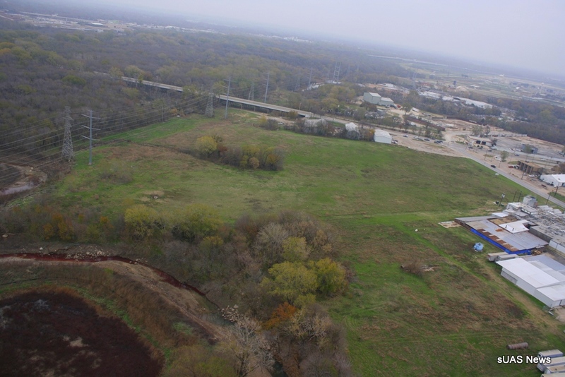
Please see this warning from the Los Angeles Police Department, sent to the California Association of Realtors. Discussion on helifreak here. More background and discussion here. I'll be talking to the NYT about this tomorrow.
Short form: Amateur UAV use within the usual FAA guidelines (under 400ft, within visual line-of-sight, away from built-up-areas) is allowed, as always. But commercial use requires a COA, which you're not going to get. So there's nothing new here, but it's a reminder that the guidelines will be enforced.
LAPD Warning Against Hiring Unmanned Aircraft Operators for Aerial Photos
Los Angeles authorities have asked C.A.R. to communicate this warning to REALTORS® who hire unmanned aircraft operators to take aerial photographs for marketing high-end properties. Using these devices (also known as drones) for flight in the air with no onboard pilot may violate, among other things, the Federal Aviation Administration's (FAA) policy on unmanned aircrafts, and Los Angeles's local ordinance requiring permits for filming commercial motion pictures and still photographs.
The Los Angeles Police Department's (LAPD) investigation has apparently revealed that aerial photos where unmanned aircraft were observed have appeared on certain real estate sales websites. According to FilmL.A., the LAPD Air Division has issued this warning as it intends to prosecute violators in the near future. FilmL.A. is a public benefit company created by the City and County of Los Angeles to manage film permit activity and related issues.
Under the Federal Aviation Administration (FAA)'s current policy, no one can operate an unmanned aircraft in the National Airspace System without specific authority. Operators who wish to fly an unmanned aircraft for civil use must obtain an FAA experimental airworthiness certificate, which will not be issued to an unmanned aircraft used for compensation or hire. Although the FAA allows hobbyists to fly model airplanes for recreational purposes under specific guidelines, that authority does not extend to operators flying unmanned aircraft for business purposes. More information is available from the U.S. Department of Transportation’s Notice on Unmanned Aircraft Operations and the FAA's policy.
Although both iOS and Android devices allow developers to get access to gyro/accel/mag data fusion output, it's not as low-level as developers of autopilots would like. Make Windows 8 will get closer.
From The Verge:
Microsoft's Windows 8 operating system will include improved sensor support, introducing new hardware sensors for the first time in some cases, and an easy way for developers to target and make use of the hardware with Metro Style applications. Microsoft is building in adaptive brightness, automatic screen rotation, and compass support based on a number of sensors: ambient light sensor, accelerometer, magnetometer, and gyroscope.
Similar sensor support can be found in Android and iOS operating systems, but Microsoft also revealed its own "sensor fusion" support for Windows 8 today, a way for developers to use the power of each sensor together to combat the various weaknesses in each individual implementation. The combination of multiple sensors can provide better data for application developers, and sensor fusion appears to be designed to aggregate this. That, too, isn't a new concept, but perhaps Microsoft will make combined sensor algorithms more exposed than in the mobile realm. It's not clear exactly how accessible it will be, but Microsoft hopes the simple API support for developers will allow them to build Metro Style and desktop applications that use a variety of sensors, and in turn better apps for end users.
Developers with access to the Samsung Windows 8 slate PC can access the sensor support immediately, and other developers can purchase a development board that attaches via USB to test out the sensor experience. Microsoft's first beta copy of Windows 8 will be made available in late February, and we're expecting to hear more from hardware vendors throughout the year as they plan to bring these sensors to life inside future Windows tablets and slates.
The folks MAVlab team from the Delft University, faculty of aerospace engineering, have been actively involved in the paparazzi community. They have been part of the the paparazzi community since 2006 and have different MAV projects running in the lab. The subjects of thier projects have covered a very wide range: From swarming over autonomous spot landing, Hybrid uav`s (quads with wings), flapping wing (www.DelFly.nl), fixed wing, rotary wing, electronics (yapa, imu`s), control and filtering software, vision algorithms, indoor operation,..
To strengthen the knowledge/expertise in thier lab they are looking to good people to do join for phd on MAV`s. If someone is actively involved in MAV`s have a master degree in engineering, computer science, computer vision. Please contact them with your cv to microuav@gmail.com. Please do include information (pictures, youtube movies) on MAV related project`s.
It's free and open! Current issue has an interesting paper on sensorless control of DC motors with a Kalman filter.
The journal covers:
"...international activities that relate to the design (mechanical, control architectures, actorics, sensorics...), experimental results and applications of:
A perfect combination of my twin passions, 3D printing and copters! From Hackaday:
If you’re like us, you’ve been infatuated with the small RC helicopter you picked up on Amazon up until the point where it careened off a wall and broke its blades. Now that you’re wondering about what to do with that small pile of plastic, metal, and electronics, why not print some helicopter blades on your 3D printer?
[Taylor] printed these blades on his Utilimaker, but we don’t see why they couldn’t be printed on a Makerbot or other RepRap. The first set of printed blades worked on the top rotor, but they were too heavy when all four blades were replace. The parts were edited in netfabb using a 0.08mm layer height and now they’re working perfectly. As far as free tools go, Slic3r is the new hotness for .STL to Gcode conversion and now that [Taylor] put the files up on Thingiverse, anyone can print a set of spare blades.
Firefly Mark One Flies in TREX Configuration. It's like a Space Odyssey!
As you can see above the 3D printed frame project has advanced one more step. I have fitted the 3D printed hub with 4 cut down TREX 450 (12mm) tail booms. It's being flow in Stability Mode. Just a note on cutting the aluminium tail booms, the easiest way I found was using a plumbers copper pipe cutter.
PID Settings:
For those who are curious, I am flying Arducopter v2.22b4, the latest version served up by Mission Planner. I dialed back the default P values for yaw, roll, pitch and throttle to 80%. The default values are too aggressive for such a small frame. I think I could dial it back even further to 75% or 70% still be responsive. I initially used 50% of default, and it was stable, but response was to slow.
All connected up with cool 3 bladed props 8x4", Unfortunately on it's first lift off took a dump and lost one of the blades on a prop, and I had no spares. Now I have to run with the 9" 2 blade props. ;-(
The next step is to fly with the integrate micro 10g motors, using the integrated arms:
Unfortunately, I was testing one of the motors, while holding it in my hands and it slipped out, and ripped itself apart. Lesson learned, "Don't underestimate the torque of these little 10g motors". Now I have to wait for another round of HK delivery. Anyone know how to rewind these little motors?


A very simple platform used for this an Exposure, long thread in RCG about them.
That river is blood red on the left!
This is the perfect reason to allow simple systems access to the NAS.
I've been experimenting with using an Arduino-powered vision system to detect and locate point light sources in an environment. The hardware setup is an Arduino Duemilanove, a Centeye Stonyman image sensor chip, and a printed pinhole. The Arduino acquires a 16x16 window of pixels centered underneath the pinhole, which covers a good part of the hemisphere field of view in front of the sensor. (This setup is part of a new ArduEye system that will be released soon...)
The algorithm determines that a pixel is a point light source if the four following conditions are met: First, the pixel must be brighter than it's eight neighbors. Second, the pixel's intensity must be greater than an "intensity threshold". Third, the pixel must be brighter, by a "convexity threshold", than the average of it's upper and lower neighbors. Fourth, the pixel must similarly be brighter, by the same threshold, than the average of it's left and right neighbors. The algorithm detects up to ten points of light. The Arduino script then dumps the detected light locations to the Arduino serial monitor.
A 16x16 resolution may not seem like much when spread out over a wide field of view. So to boost accuracy we use a well-known "hyperacuity" technique to refine the pixel position estimate to a precision of about a tenth of a pixel. The picture below shows the technique: If a point of light exists at a pixel, the algorithm constructs a curve using that pixel's intensity and the left and right intensities, then interpolates using a second order Lagrange polynomial, and computes the maxima of that polynomial. This gives us "h", a subpixel refinement value that we then add to the pixel's whole-valued horizontal position. The algorithm then does something similar to refine the vertical position using the intensities above and below the pixel in question. (Those of you who have studied SIFT feature descriptors should recognize this technique.) The nice thing about this technique is that you can get the precision of a 140x140 image for "light tracking" without exceeding the Arduino's 2kB memory limit.
The algorithm takes about 30 milliseconds to acquire a 16x16 image and another 2 or 3 milliseconds to locate the lights.
The first video shows detection of a single point light source, both with and without hyperacuity position refinement. When I add a flashlight, a second point is detected. The second video shows detection of three lights (dining room pendant lamps) including when they are dimmed way down.
It would be interesting to hack such a sensor with a quadrotor or another robotic platform- Bright lights could serve as markers, or even targets, for navigation. Perhaps each quad rotor could have an LED attached to it, and then the quad rotors could be programmed to fly in formation or (if you are brave) pursue each other.
With additional programming, that sensor could also implement optical flow computations much like I had done in a previous post.
SOURCE CODE AND PCB FILES:
The main Arduino sketch file can be found here: LightTracker_v1.zip
You will still need library files to run it. I've put these, as well as support documentation and Eagle files for the PCBs, in the downloads section of a Google Code project file, located here: http://code.google.com/p/ardueye-rocket-libraries/downloads/list
Andrew Tridgell ("Tridge") is a well-known programmer in the open source world (Samba, etc) and one of the leaders of the APM dev team. His UAV team, CanberraUAV, will be competing in this year's Outback Challenge with an APM-powered Telemaster, and at the Australian Linux conference he gave a spectacular lecture about the team's strategy and the technological challenges in the competition.
This is a must watch for anyone interested in more advanced UAV functions. Tridge and his team have added a Panda board to APM to do image processing. This is a great opportunity to watch a world-class technologist explain the strategy they're using to try to win this competition.